Craftsman Marine CM4.65 User manual

PropulsionCrafted with craftsman marine
CM4.65
& CM4.80
Engine manual


3Crafted with CRAFTSMAN MARINE
Preface
Dear owner of this engine,
We would like to thank you very much for your decision to procure a marine diesel
engine, made by Craftsman Marine.
Provided you will make proper use of it and take care of adequate maintenance, this
engine will serve you faithfully and trouble-free, for many years to come.
This instruction manual informs you about the control, the maintenance and the
inspection of the Craftsman Marine diesel engines, models CM4.65 and CM4.80.
Please store this manual in an accessible place.
Should you have any further questions after having read this manual, we shall be
delighted to be of service.
Craftsman Marine B.V.
This page will provide you with a survey of all warning pictograms, used throughout
this manual. Notes referring to safety issues show this symbol:
Please adhere strictly to the recommendations in this chapter and instruct anybody
else, who may be operating or servicing the engine, to do likewise. These are the
safety recommendations:
• Never touch any moving parts when the engine is running.
• When in operation the engine (or certain parts thereof) may becomevery hot.
Do not ever touch these parts and be very careful with flammable products in the
neighbourhood of the engine.
• When checking upon or adjusting any parts, or when checking or filling
lubricants or cooling liquids, make sure that the engine is stopped.
• Do not open the filler cap on the expansion tank or on the heat exchanger unless
the engine is completely cooled down.
• Maintenance and service to the engine must only be provided by experienced
people, using suitable tools. If possible entrust only an authorized Craftsman
Marine dealer to do such work.
(especially with a view to a safety risk for man or material)
Safety
DANGER
ATTENTION
Pay attention to the symbols and read the instructions in the
text.
Attention

4 Crafted with CRAFTSMAN MARINE
This manual applies to model CM4.65 and model CM4.80. Therefore, it can happen
that a drawing or picture is not always an exact referral to the engine that you have
purchased. Please read this manual carefully before commissioning the engine.
Improper use of this engine may cause accidents and all warranty conditions may
become invalid.
In this manual you will also find detailed instructions of how and how regularly the
various components of your engine must be serviced. This engine must be used
exclusively in accordance with the prescription given in the General Conditions of
Sale and Supply.
In the case of deviating use the manufacturer does not accept any responsibility
whatsoever for resulting damage. This type of risk is to be borne exclusively by the
user.
Correct and proper use also implies strictly adhering to the prescriptions of
operation, maintenance and repair. Only such persons, who are acquainted with the
operation, the maintenance and the repair of your engine, and who are fully aware of
any danger involved, should be allowed to work at your engine.
Note:
For that reason, always have your engine serviced, maintained and repaired by an
authorized CRAFTSMAN MARINE dealer.
In the case of modifications of the engine, which have not been previously approved
by Craftsman Marine in writing, the responsibility of the manufacturer for any
resulting damage is immediately rendered null and void.
Modifications of the injection and distribution system also form part of the aforemen-
tioned exclusion of the manufacturer’s warranty. Moreover, they may affect the
performance of the engine and the exhaust gas emission in a negative fashion.
It may be possible that the fulfillment of the legal prescriptions regarding the
emission of exhaust gases, aiming at the protection of the environment, is no longer
guaranteed in that case.
Disclaimer
The specifications and the descriptions in this instruction manual were correct at the time of going to press. However, Craftsman Marine is continuously striving after the
improvement of its products and therefore reserves the right to modify – at all times and without prior notification - product specifications and instruction manuals.

5Crafted with CRAFTSMAN MARINE
Table of contents
Safety
9
10
11
12
14
13
8
3
2
1
4
5
6
7
Disclaimer
Product identification
Product description
Standard scope of supply
Service side
CM4.80 with ZF25 Gearbox
Starter motor side
CM4.65 with TM345 Gearbox
Prior to commissioning the engine
Maintenance and inspection
Winter storage
Preparations for the new season
Problems and solutions
Technical data
Lubricants and cooling liquids
Overall Dimensions
Topping up the lubrication oil
Changing of the engine lubrication oil
Replacing the oil filter
Adding new oil
Checking of oil level in gearbox
Check-up of coolant level
Replace cooling liquid
Check-up of raw water pump impeller
Impeller removal
Checking of the cooling water strainer
Draining of the water separator/fuel filter
Inspection of the V-belt
Engine operation
Calorifier installation
Maintenance schedule
Engine lubrication oil
Gearbox
Cooling liquid
Engine panel
First check
The starting procedure
Monitoring lights oil pressure and battery
charging current
Electric engine stop
4
3
7
8
10
8
40
9
41
11
20
30
32
34
38
42
40
20
21
21
21
22
23
23
24
24
25
26
29
16
18
19
11
12
13
14
16
16
17
17

6 Crafted with CRAFTSMAN MARINE
Notes

7Crafted with CRAFTSMAN MARINE
Product identification 1
The Craftsman Marine identification tag is the place to
find the engine model, the serial number and a few
more data concerning your engine.
Please make sure this information is correctly noted in
the service and warranty book.
The Craftsman Marine identification tag is located on
top of the rocker cover, next to the oil filler cap.
The Hyundai engine serial number is engraved into the
engine block to the starboard side and into the flywheel
housing.
Identification tag Position of the identification tag Hyundai engine serial number
You will need this information if and
when you have to order spare parts, or
if you want to correspond with our
service department.

8 Crafted with CRAFTSMAN MARINE
2 Product description Service side
Alternator
V-Belt
Raw water pump
( Ø 28 mm )
Engine Oil Cooler
Drain plug internal cooling
system
Drain valve internal cooling
system
Exhaust injection bend
( Ø 60 / Ø 75 mm)
Heat exchanger Air inlet silencer
Oil filter

9Crafted with CRAFTSMAN MARINE
2Product description
Starter motor side
Oil filter cap
Connection to fuel
supply (Ø 8 mm)
Fuel supply pump
Starter motor
Fuel filter
Filler cap inner cooling circuit
Connections of
electrical system &
fuse

10 Crafted with CRAFTSMAN MARINE
Standard scope of supply
By carefully adhering to the following recommendations, you will be sure of the best
possible conditions to operate your engine, resulting in a long life span, excellent
performance and fuel economy.
• Engine instrument panel
• Engine cable loom with fuse and Multi-plugs
• Connection parts for the push-pull cables
• Four flexible engine mountings
• Sump pump
• Have the maintenance procedures regularly executed, as mentioned in this
manual.
• Prior to starting the engine, always verify the correct level of the various fluids.
• All year long, use a good quality anti-freeze product, protecting your engine
against corrosion and frost damage. Please see page 41 for the specifications of
the cooling liquid.
• Do not ever put the engine into operation without a properly functioning
thermostat, so as to avoid overheating of the engine.
• Always use the correct quality of lubricants, as specified on page 11 of this
manual.
• Always use good quality diesel fuel, free from water and /or other impurities.
• Switch-off the engine immediately if the monitoring light(s) of oil pressure, fresh
water temperature, raw water temperature and/or battery charging control light
up.
• Fuel filter/water separator in the fuel supply line (recommended)
(optional):
For an optional list of supply list take a look at our website
www.craftsmanmarine.com
3

11Crafted with CRAFTSMAN MARINE
Prior to commissioning the engine
The Craftsman Marine diesel engines are supplied
without lubrication oil.
Before commissioning the engine for the first time, it
must be filled with 5.4 liters of lubrication oil for diesel
engines, with following specifications:
Type: 15W40
API: CD, CE or CF4
CCMC: D4 or D5
The engine can be filled with oil through the filler cap
on the rocker cover.
Engine lubrication oil
When the filling of oil is completed,
check with the dipstick whether the
level of lubricating oil is correct.
4

12 Crafted with CRAFTSMAN MARINE
Prior to commissioning the engine
The gearbox is located at the rear of the engine and it
must also be filled with the correct type and quantity of
lubricant.
Craftsman Marine diesel engines are supplied with
gearboxes of several brands and types.
For the ZF-Hurth and Technodrive brands the types and
quantities are specified on the right side of this page.
Please consult the appropriate instruction manuals in
the case of other gearbox makes and models.
Gearbox
ZF-Hurth
Type ZF25: 2.2 litres ATF*
Type ZF25A: 2.0 litres ATF*
Type ZF25M: 0.8 litres ATF*
Technodrive
Type TMC345: 1.8 liter SAE 20/30
Type TMC345A: 1.8 liter SAE 20/30
* Automatic Transmission Fluid, type A, suffix A.
Here it is shown how the gearbox can be filled up with
its lubricant. When the filling is completed, verify with
the dipstick whether the correct level of fluid is
obtained.
4

13Crafted with CRAFTSMAN MARINE
Prior to commissioning the engine
Prior to commissioning the engine for the first time, the
inner cooling circuit must be filled with cooling liquid.
In order to do so, the filler cap on top of the heat
exchanger housing must be removed and the drain
valve A on the engine must be opened. By opening the
valve, the cooling liquid can flow directly from the heat
exchanger housing into the cooling channels of the
engine.
The cooling system must be filled with 9 liters of
cooling liquid. You can fill the system with a ready-to-
use product, or prepare a mixture of 40% anti-freeze (on
the basis of ethylene-glycol) and 60% of clean tap
water.
Fill the system to about 1 cm below the bottom of the
filler pipe. The system will breathe automatically. Do
not forget to put the filler cap in place again and close
the drain valve on the engine.
Once the engine being commissioned and having run for
the first time, verify again the level of the cooling liquid
and top up, if necessary.
When a calorifier is installed and connected to the
engine (page 18), an additional expansion tank must be
installed When the calorifier is installed higher than the
engine, it will not bleed automatically when filling the
cooling system. Fill it separately to bleed the cooling
system completely.
Cooling liquid
Open
Drain valve positions
Close
When running
engine
When filling
coolant
Never fill the cooling system with sea
water!
4
A

14 Crafted with CRAFTSMAN MARINE
Prior to commissioning the engine
Instrument panel
1. Revolution counter / hour counter
2. Voltmeter
3. Starter switch
4. Monitoring light temperature raw water
5. Monitoring light oil pressure engine
6. Monitoring light cooling liquid temperature
7. Sensor for automatic backlight dimming
8. Monitoring light charging current
9. Monitoring light pre-heating system
10. Low oil pressure gearbox
The voltmeter may be replaced by a temperature gauge
Optional
4. 5. 6. 7. 8. 9. 10.
1.
2.
3.
4

15Crafted with CRAFTSMAN MARINE
Prior to commissioning the engine
The revolution counter indicates the number of the
engine’s revolutions per minute. When underway, do
not let the engine run at maximum revolutions during a
prolonged period of time. Also, do not have the engine
idling for more than a few minutes and never run the
engine at full throttle, in order to heat it up quickly.
The hour counter indicates the total running time of the
engine in hours.
The CM 4.65 and CM 4.80 marine diesel engines both
have an idling speed of 850 rpm.
The voltmeter shows the voltage of the battery. When
the engine is stopped and the starter switch turned to
‘on’ or ‘pre-heat’ the battery voltage must be about 12
Volt. When the engine is running the figure must read
between 12 and 14.5 Volt.
Revolution counter / hour counter Voltmeter Monitoring lights
1. 2. 3.
4. 5. 6.
The instrument panel features six monitoring lights for,
respectively:
1. oil pressure
2. battery charging current
3. temperature inner cooling circuit
4. temperature raw water in the exhaust
5. low oil pressure gearbox
6. pre-heating
These monitoring lights, except the pre-heating
monitor, are connected to a buzzer. If the buzzer
becomes audible (and a monitoring light illuminates)
when the engine is running, a problem has occurred to
one of the functions described here above.
In that case, stop the engine
IMMEDIATELY!
4

16 Crafted with CRAFTSMAN MARINE
Engine operation
• Oil level
• Coolant level inner circuit
• Is the raw water seacock opened?
• Is the main electrical switch ‘on’?
• Is the gearbox lever in the neutral position?
The time required for pre-heating the engine is determined
by the ambient temperature. The lower the temperature, the
longer the pre-heating procedure will take. At freezing
temperature, it may take as long as 20 seconds; and up to
10 seconds at temperatures of up to 7 degrees celsius. Do
not pre-heat the engine any longer than 1 minute maximum.
First check The starting procedure Note:
Always check on following points, before starting the
engine:
1. Prior to starting the engine, position the throttle lever at
half of its travel, without engaging the gearbox.
2. Turn the key from the ‘off’ position one step further to
the right, to the ‘on’ position. The monitoring lights for
oil pressure, charging current and pre-heating will light
up and the buzzer is audible.
3. From the ‘on’ position turn the key one step further to
the right, to the ‘pre-heating’ position. Now only the
pre-heating monitoring light is burning. Keep the key
about 6 seconds in this position (at an ambient
temperature of 15° C or more).
4. Then turn the starter key one step further to the right, to
the ‘start’ position and release the key as soon as the
engine springs to life; the key will return automatically
to the ‘on’ position, where it will remain parked as long
as the engine is running. Have the engine running at
idling revolutions during a short period of time, so that
the engine will warm-up to some extent.
Stop the starting procedure if the engine does
not come to life within 10 seconds. Release
the key and wait till the starter motor has
come to a complete stand-still before giving it
another try. Do not have the starter motor
running during more than 30 seconds contin-
nously, in order to avoid damage by overhe-
ating.
5

17Crafted with CRAFTSMAN MARINE
Engine operation
Monitoring lights oil pressure and battery charging
current
Electric engine stop
Make sure that the monitoring lights for oil pressure and
charging current are extinguished and that the buzzer is
silent. Check if cooling water is coming out of the exhaust
line. If not so, stop the engine IMMEDIATELY.
Before stopping the engine, shift the throttle lever back to
its neutral position, place the gearbox lever into the neutral
position and let the engine idle during a few moments. Turn
the starter key to the ‘OFF’ position to stop the engine. After
a long trip it is recommended to have the engine idling for a
few minutes, before putting it to full stop.
Close the seacock of the raw water inlet and turn the main
electrical switch to the off position, if the engine will not be
used during a prolonged period of time.
Never turn the electric main switch to the
‘off’ position when the engine is running.
Also: do not turn the starter switch to the
‘start’ position when the engine is
running. This may cause serious damage
to the starter motor.
5

18 Crafted with CRAFTSMAN MARINE
Calorifier installation
6
Calorifier in Engine
Calorifier out Engine
Calorifier in Engine
Calorifier out Engine
Calorifier/water heater connection points come fitted as
standard on this engine. It’s important that the calorifier
is installed according to the installation manual
provided by the manufacturer.
The engine coolant connection on the calorifier should
be connected to point A, the coolant return should be
connected to point B.
Connecting a calorifier to the engine Ball valves Header tank and bleeding
In case of a malfunction of the calorifier or one of its
components it’s important that it can be disconnected
from the engine’s cooling circuit. It is advised to add
ball valves and a bypass line. In normal operation the
bypass line is closed. When the coolant lines to the
calorifier are closed, the bypass line must be opened,
otherwise, part of the engine cooling circuit is inter-
rupted (see schematic above).
Note that the ball valves should not restrict the
waterflow and must have a minimum ID of 12mm.
With the calorifier installed a header tank must be
added to the cooling circuit of the engine. In case the
water heater has to be placed above the engine header
tank, the engine water hose circuit must be equipped
with an air bleeder valve on the highest point.
A
B
normal operation bypass operation

19Crafted with CRAFTSMAN MARINE
7Maintenance schedule
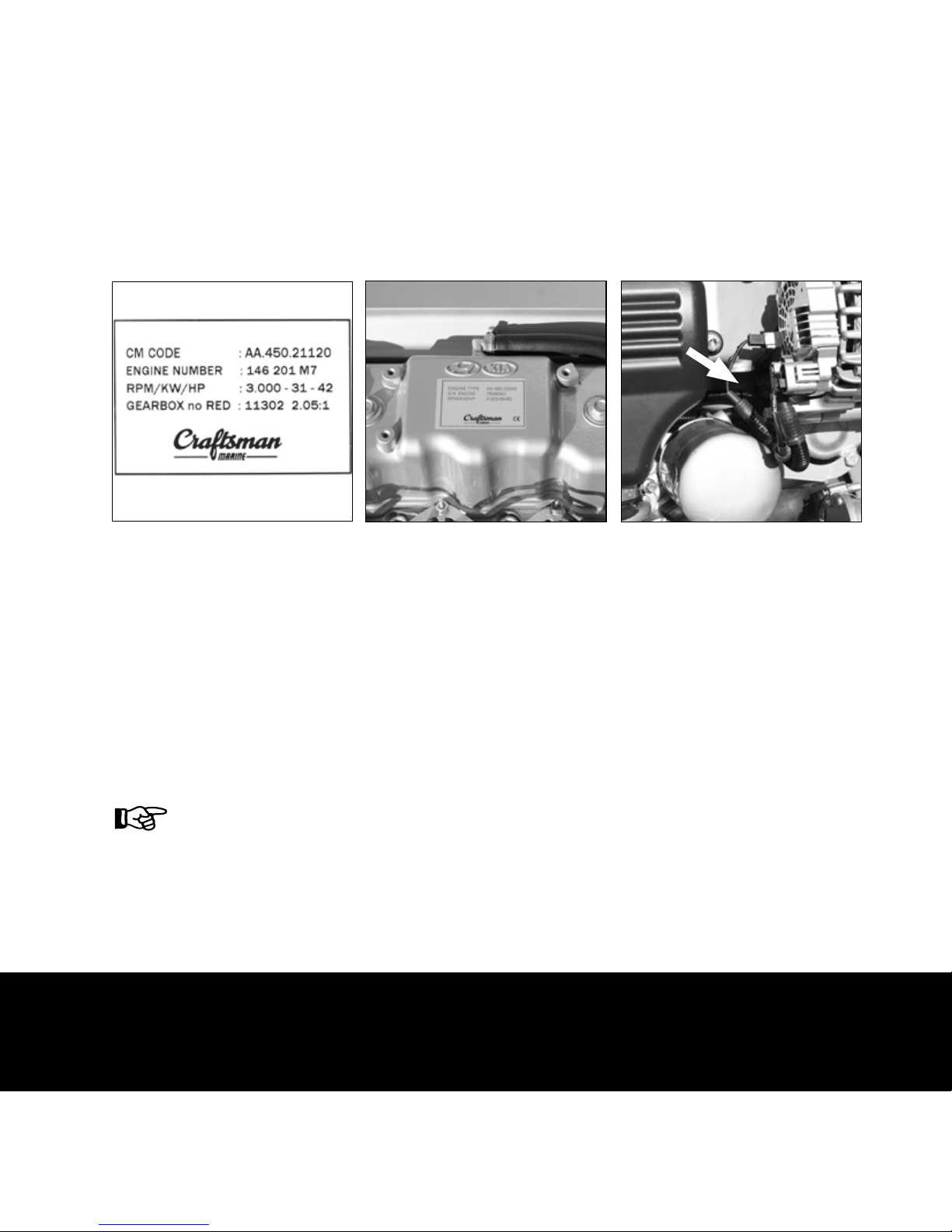
Recording of data for verification
After every 10 hours of operation or each time before starting
After the first 50 hours of operation
After every 100 hours of operation (or at least once a year)
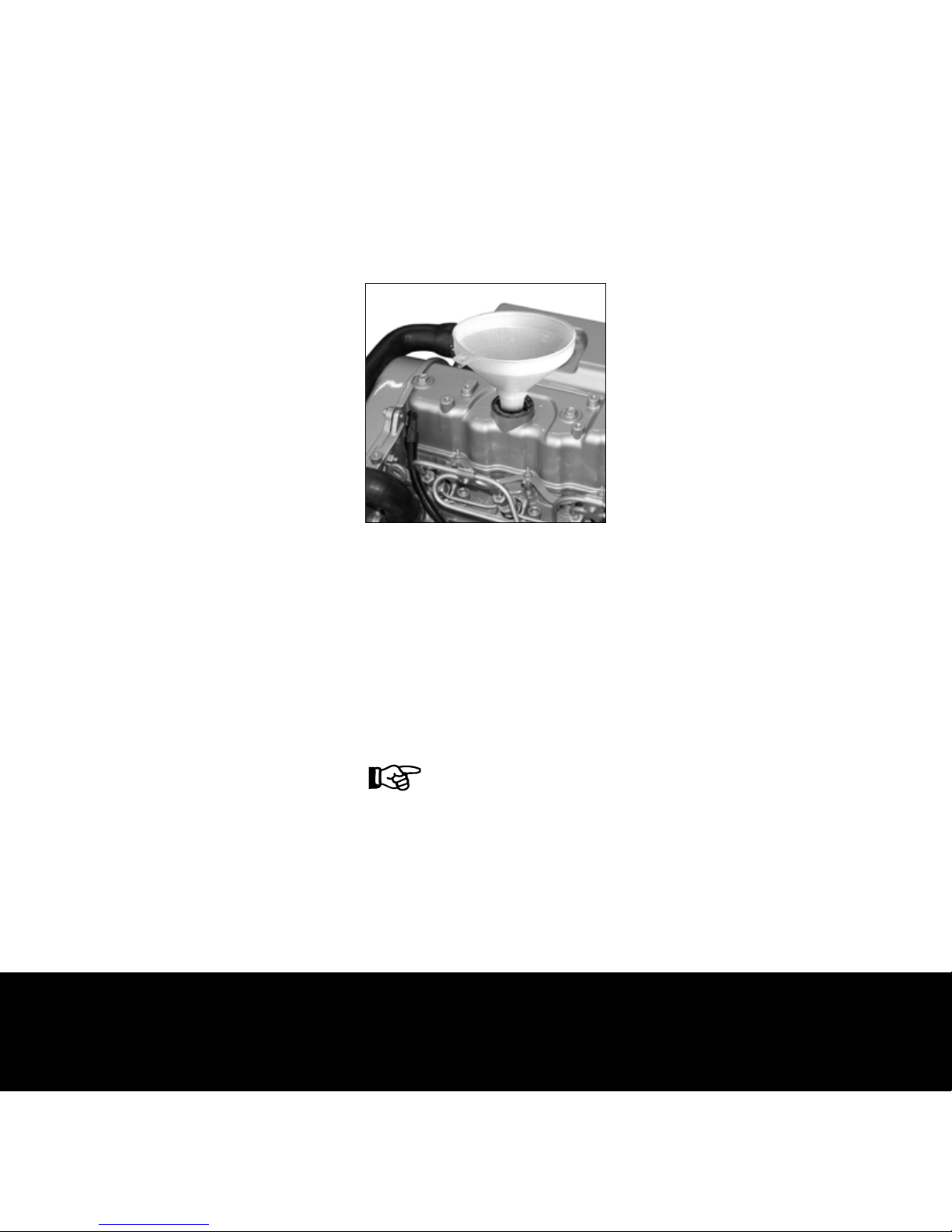
• Check level of engine lubricating oil (page 20)
• Check level of cooling liquid (page 23)
• Check cooling water strainer for blockage of the water flow (page 25)
Ask your dealer to execute this maintenance job:
Ask your dealer to execute this service job:
• Drain water from the fuel filter/water separator (page 27)
• Change engine lubrication oil (page 20)
• Replace oil filter (page 21)
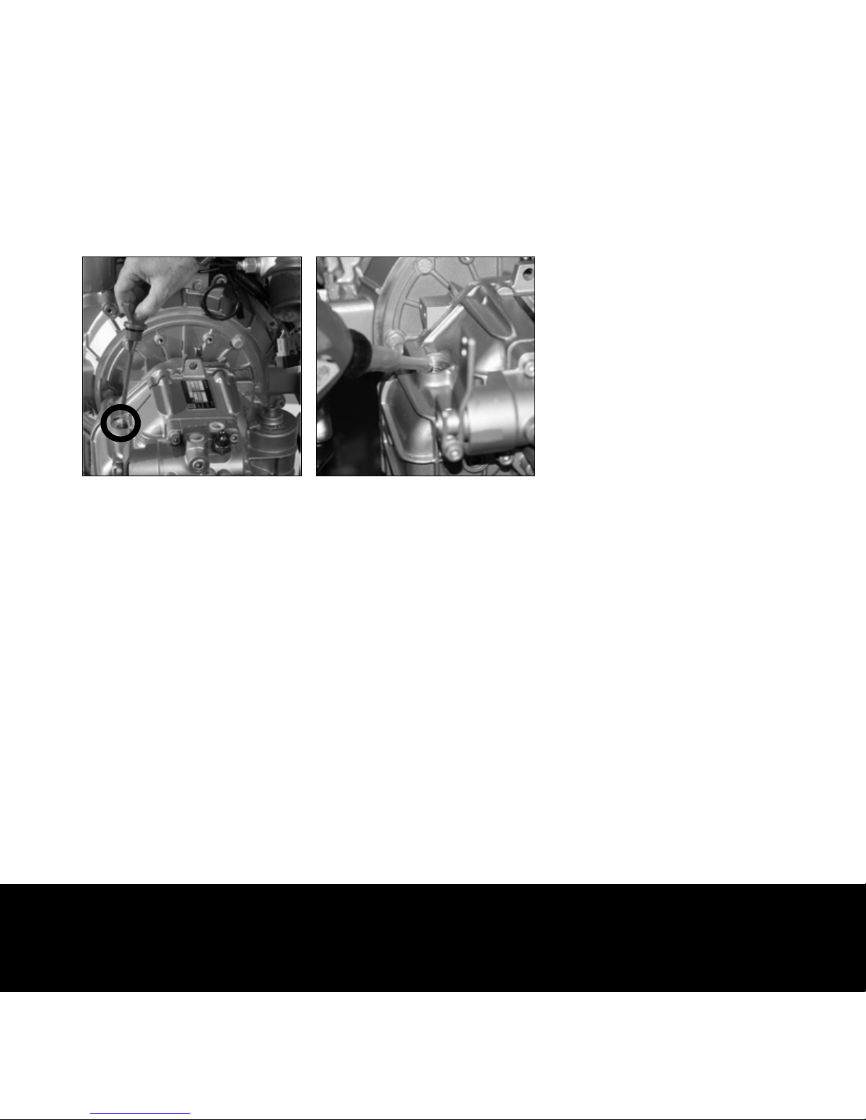
• Change lubricating fluid in gearbox (page 22)
• Replace fuel filter (page 26)
• Verify idling revolutions and adjust if necessary (page 15)
• Drain water from the fuel filter/water separator
• Change engine lubrication oil
• Replace oil filter
• Verify level of lubricating fluid in gearbox
• Replace fuel filter
• Check batteries, electrical cables and connections
• Check impeller raw water pump
In order to ensure a long life span of your engine, it is imperative to adhere to the following directives pertaining to the periodical maintenance of the engine and its compo-
nents. In the case of inadequate maintenance, serious damage can be caused to the engine and no warranty claim can be accepted by the manufacturer. These are the jobs to
be performed:
After every 500 hours of operation (at least once a year)
Have your dealer check and execute the following:
• Verify the tolerance of the valves
• Replace the fuel filter
• Change the oil in the gearbox
• Clean the filter, which is located just before the fuel lift pump
• Verify the flexible engine mountings for the rubbers to have the correct
compression and adjust if necessary
• Check all hoses and hose connections for leaks
• Verify the tension of the V-belt
After every 1000 hours of operation (or at least once every two years)
After every 1600 hours of operation (or at least once every 10 years)
Have your dealer check and execute the following:
Ask your dealer to execute this maintenance job:
If necessary
• Verify the proper functioning of the raw water pump
• Replace the cooling liquid in the inner cooling circuit
• Check valve clearance and adjust if required
• Replace timing belt
-Bleed the fuel system (page 27)
-Verify the number of revolutions when idling (page 15)
Only service the engine when it is stopped!

20 Crafted with CRAFTSMAN MARINE
8 Maintenance and inspection
In order to verify the level of lubricating oil, the engine
must be stopped and cooled down.
The dipstick is located at the right side (seen from the
front) of the engine, next to the injection pump.
The markings on the dipstick indicate the upper and the
lower limit of the oil level. The correct oil level is
spot-on or close to the upper mark. If the engine has not
enough oil, fresh oil of the same specifications must be
added. The difference between the upper and the lower
mark is about 2 liters of oil.
Any lubricating oil in excess will be burnt in the
cylinders, causing black smoke from the exhaust and
strong internal pollution of the engine.
Dipstick Oil level Topping up the lubrication oil
The filler cap is located on top of the rocker cover at the
front of the engine. After topping up wait for 5 minutes
to verify the oil level.
Do not spill oil over the engine; better
use a funnel when adding oil.
Make sure that no oil is added above the
upper mark of the dipstick.
This manual suits for next models
1
Table of contents
Popular Engine manuals by other brands

MTU
MTU 12 V 2000 S96 operating instructions

Danfoss
Danfoss EM-PMI540-1500 user guide

Nice
Nice RDF-140-20 Instructions and information for installation and use

Becker
Becker R30/17C SE I1 Assembly and operating instructions

Kohler
Kohler COMMAND 20-25 HP owner's manual

Briggs & Stratton
Briggs & Stratton 400000 Professional Series Operator's manual