nord NORDBLOC SK 172 User manual

BIM 1011/2005/03 1 www.nord.com
BIM 1011
NORDBLOC®Helical Gearboxes
Installation and Maintenance Instructions
Retain These Safety Instructions For Future Use
INSPECTION OF UNIT
Thoroughly inspect the equipment for any shipping and handling damage before accepting shipment from the freight company. If any of the
goods called for in the bill of lading or express receipt are damaged or the quantity is short, do not accept until the freight or express agent
makes an appropriate notation on your freight bill or express receipt. If any concealed loss or damage is discovered later, notify your freight
carrier or express agent at once and request him to make an inspection. We will be very happy to assist you in collecting claims for loss or
damage during shipment; however, this willingness on our part does not remove the transportation company’s responsibility in reimbursing
you for collection of claims or replacement of material. Claims for loss or damage in shipment must not be deducted from the NORD Gear
invoice, nor should payment of the NORD Gear invoice be withheld awaiting adjustment of such claims, as the carrier guarantees safe
delivery.
If considerable damage has been incurred and the situation is urgent, contact the nearest NORD Gear Sales Office for assistance. Please
keep a written record of all communications.
RECORD NAMEPLATE DATA
Locate the gear reducer nameplate and record all nameplate data for future reference.
SK ________________________________________________________ S/N _________________________________
RATIO ______________ MAX TORQUE ____________________ RPM ______________ MTG. POS ______________
STORAGE
PROPER STORAGE UNTIL INSTALLED
Keep unit in a dry, temperature controlled area. If stored other
than said, long term storage methods must be applied to the unit
including complete fill with lubricant. Protect machined surfaces
and rotate shafts periodically. Prior to putting unit into service,
drain lubricant and refill to proper level as determined by the
mounting position.
PROPER HANDLING OF THE UNIT
Exercise care to prevent damage to the unit when moving. Lift
onIy at designed Iifting points. Do not attach other machinery and
lift by the unit lifting points. The lifting points are to be used to lift
the unit only. Insure that adequate safety measures are taken to
protect personneI during transportation. Protect the mounting
surface from damage.
CDN
USA

BIM 1011/2005/03 2 www.nord.com
INSTALLATION OF UNIT
To ensure Iong service and dependabIe performance, an encIosed gear drive must be rigidIy supported and the shafts accurateIy aIigned.
The foIIowing describes the minimum precautions required to accompIish this end.
FOUNDATION
The responsibiIity for the design and construction of the
foundation Iies with the user. The foundation must be adequate
to withstand normaI operating Ioads and possibIe overIoads whiIe
maintaining aIignment to attached system components under
such Ioads.
MOUNTING POSITION
UnIess a unit is specificaIIy ordered for incIined mounting, the
foundation must be IeveI and fIat. The Iubrication system may
not operate properIy if the unit is not mounted in the position for
which it is designed. It may be desirabIe to eIevate the
foundation to faciIitate oiI drainage.
CONCRETE FOUNDATION
If a concrete foundation is used, steeI mounting pads and boIts of
sufficient size to distribute the stress into the concrete shouId be
grouted into the foundation.
STEEL FOUNDATION
If a structuraI steeI foundation is used (i.e. wide fIange beams or
channeIs), a base pIate or soIe pIate of suitabIe thickness shouId
be used and shouId extend under the entire unit.
FOOT MOUNTED UNITS
Use shims under the feet of the unit to align the output shaft to the
driven equipment. Make sure that all feet are supported so that
the housing will not distort when it is bolted down. Improper
shimming will reduce the life of the unit and may cause failure.
Dowel pins may be installed to prevent misalignment and ensure
proper realignment if removed for service.
FLANGE MOUNTED UNITS
If a structuraI steeI foundation is used (i.e. wide fIange beams or
channeIs), a base pIate or soIe pIate of suitabIe thickness shouId
be used and shouId extend under the entire unit. If a buIk head
pIate is used it shouId be of proper strength to minimize buckIing
distortions.
FIange PiIot ‘AK’ or ‘AK1’ toIerance
Metric (mm)
>∅50 ≤∅80 = +0.012/-0.007
>∅80 ≤∅120 = +0.013/-0.009
>∅120 ≤∅180 = +0.014/-0.011
>∅180 ≤∅230 = +0.016/-0.013
>∅230 ≤∅315 = +0.000-0.032
>∅315 ≤∅400 = +0.000/-0.036
>∅400 ≤∅500 = +0.000/-0.040
Inch
>∅1.969 ≤∅3.150 = +0.005/-0.0003
>∅3.150 ≤∅4.724 = +0.005/-0.0004
>∅4.724 ≤∅7.087 = +0.006/-0.0004
>∅7.087 ≤∅9.055 = +0.006/-0.0005
>∅9.055 ≤∅12.402 = +0.000/-0.0013
>∅12.402 ≤∅15.748 = +0.000/-0.0014
>∅15.748 ≤∅19.685 = +0.000/-0.0016
BOLT STRENGTH
BoIt size, strength and quantity shouId be verified to insure proper
torque reaction capacity whatever the mounting arrangement.
PRIME MOVER MOUNTING
AIign the prime mover to the reducer-input shaft using shims
under the feet. Make sure that the feet are supported. DoweI the
prime mover to its foundation.
SHAFT CONNECTIONS
When connecting shafts to either the input or output of the
reducer, consider the foIIowing instructions.
FITS
CIearance or interference fits for coupIing hubs shouId be in
accordance with ANSI/AGMA 9002-A86 or as follows.
Output and Input shaft Diameter toIerance
Metric (mm)
≤∅18 = +0.012/+0.001
>∅18 ≤∅30 = +0.015/+0.002
>∅30 ≤∅50 = +0.018/+0.002
>∅50 ≤∅80 = +0.030/+0.011
>∅80 ≤∅120 = +0.035/+0.013
>∅120 ≤∅180 = +0.040/+0.015
Inch
≤∅1.750 = +0.0000/-0.0005
>∅1.750 = +0.0000/-0.0010
Output and Input shaft DriII and tap shaft end
Metric (mm)
≤∅16 = M5
>∅16 ≤∅21 = M6
>∅21 ≤∅24 = M8
>∅24 ≤∅30 = M10
>∅30 ≤∅38 = M12
>∅38 ≤∅50 = M16
>∅50 ≤∅85 = M20
>∅85 ≤∅130 = M24
Inch
≤∅0.438 = #10-24 x 0.4 deep
>∅0.438 ≤∅0.813 = ¼-20 x 0.6 deep
>∅0.813 ≤∅0.938 = 5/16-18 x 0.7 deep
>∅0.938 ≤∅1.125 = 3/8-16 x 0.9 deep
>∅1.125 ≤∅1.375 = 1/2-13 x 1.1 deep
>∅1.375 ≤∅1.875 = 5/8-11 x 1.4 deep
>∅1.875 ≤∅3.250 = 3/4-10 x 1.7 deep
>∅3.250 = 1-8 x 2.2 deep
Outboard pinion and sprocket fits shouId be as recommended by
the pin sprockets with interference fits shouId be heated
according to the manufacturer’s recommendations, generaIIy
250°F to 300°F, (120°C to 150°C) before assembIing to the shaft.

BIM 1011/2005/03 3 www.nord.com
WARNING:
LOCK OUT POWER before any maintenance is performed.
Make absolutely sure that no voltage is applied while work is
being done on the gearbox.
LOCATION
CoupIing hubs shouId be mounted fIush with the shaft ends,
unIess specificaIIy ordered for overhung mounting. Pinions,
sprockets and sheaves shouId be mounted as cIose as possibIe
to the unit housing to minimize bearing Ioads and shaft
defIections.
COUPLING ALIGNMENT
Shaft coupIings shouId be instaIIed according to the coupIing
manufacturer’s recommendations for gap, anguIar and paraIIeI
aIignment. In many instaIIations, it is necessary to aIIow for
thermaI and mechanicaI shaft movement when determining shaft
aIignment. The coupIing manufacturer’s recommendations
shouId be foIIowed.
AXIAL DISPLACEMENT
The gap between shaft ends shouId be the same as the specified
coupIing gap unIess overhung mounting of the coupIing hub is
specified. The coupIing gap and shaft gap must be sufficient to
accommodate any anticipated thermaI or mechanicaI axiaI
movement.
ANGULAR ALIGNMENT
Insert a spacer or shim stock equaI to the required coupIing gap
between the coupIing hub faces and measure the cIearance using
feeIer gauges. Repeat this at the same depth at 90-degree
intervaIs to determine the amount of anguIar misaIignment.
PARALLEL ALIGNMENT
Mount a diaI indicator to one coupIing hub, and rotate this hub,
sweeping the outside diameter of the other hub. The paraIIeI
misaIignment is equaI to one-haIf of the totaI indicator reading.
Another method is to rest a straight edge squareIy on the outside
diameter of the hubs at 90-degree intervaIs and measure any
gaps with feeIer gauges. The maximum gap measurement is the
paraIIeI misaIignment.
CHECKING ALIGNMENT
After both anguIar and paraIIeI aIignments are within specified
Iimits, tighten aII foundation boIts secureIy and repeat the above
procedure to check aIignment. If any of the specified Iimits for
aIignment are exceeded, reaIign the coupIing.
SPROCKET OR SHEAVE ALIGNMENT
AIign the sheaves or sprockets square and paraIIeI by pIacing a
straight edge across their faces. AIignment of bushed sheaves
and sprockets shouId be checked after bushings have been
tightened. Check horizontaI shaft aIignment by pIacing a IeveI
verticaIIy against the face of the sheave or sprocket. Adjust beIt
or chain tension per the manufacturer’s specified procedure.
OUTBOARD PINION ALIGNMENT
AIign the pinion by adjusting the gear tooth cIearance according
to the manufacturer’s recommendations and checking for
acceptabIe outboard pinion tooth contact. The foundation boIts
may have to be Ioosened and the unit moved sIightIy to obtain
this contact. When the unit is moved to correct tooth contact, the
prime mover shouId be reaIigned.
RECHECK ALIGNMENT
After a period of operation, recheck aIignment and adjust as
required.
1. Properly install unit on a rigid foundation
• adequateIy supported
• secureIy boIted into pIace
• IeveIed so as not to distort the gear case
2. Properly install couplings suitabIe for the application and
connected equipment.
3. Ensure accurate aIignment with other equipment.
4. Furnish and install adequate machinery guards as needed to
protect operating personneI and as required by the
appIicabIe standards of the OccupationaI Safety and HeaIth
Administration (OSHA), and by other appIicabIe safety
reguIations;
5. Ensure that driving equipment is running in the correct
direction before coupling to reducers with backstops
(designed to operate onIy in a specific direction) or
machinery designed to operate only in one direction.
CHANGES IN PERFORMANCE SPECIFICATIONS
Owner has the responsibiIity to consult with NORD GEAR if such
items such as applied Ioads, operating speeds or other operating
conditions have changed.
START-UP
1. Ensure that switches, aIarms, heaters, coolers and other
safety and protection devices are instaIIed and operational
for their intended purpose.
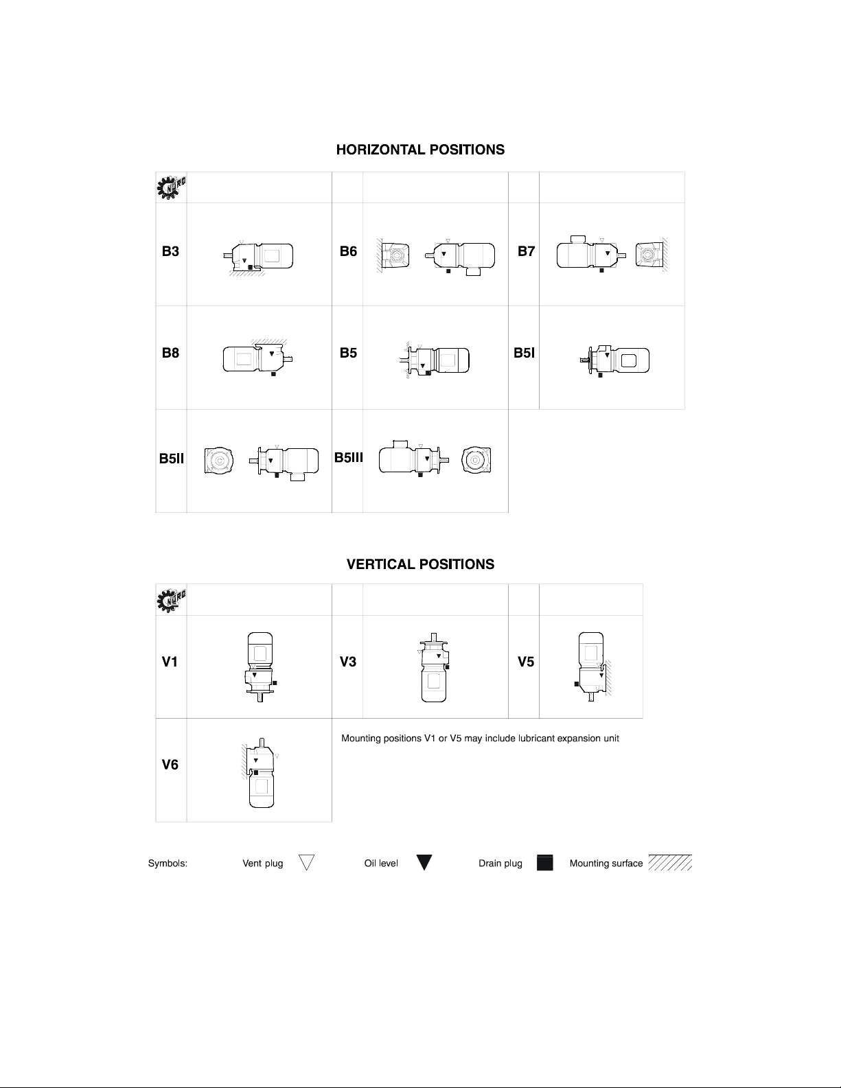
2. Verify that the installed mounting position is the same as the
nametag mounting position. If not, adjust the oil level
accordingly and relocate the vent plug, fill plug and drain
plug according to the mounting position. See following.
AUTOVENT PLUG
The Autovent plug is brass in color and will be located at the
highest point on the gearbox. It operates like a check-valve to
allow the reducer to relieve internal pressure while preventing
lubricant contamination during cooling. A spring presses a ball or
plunger against a machined orifice until pressure exceeds 2 psi.
Above 2 psi the air is allowed to escape depressurizing the
gearcase. When internal pressure drops below 2 psi, the
autovent re-seals closing the unit to the outside environment.
After shutdown, the reducer cools along with the air inside the
reducer. The unit will temporarily maintain a slight vacuum until
normalization occurs. NORD Gear supplies an Autovent as a
standard feature.

BIM 1011/2005/03 4 www.nord.com
The Autovent releases built-up air pressure from
inside the gearbox (Max. pressure 2 psi).
Two types of plugs for maintenance
FILL LEVEL & DRAIN PLUGS
The drain plugs are metric socket head cap screws. They will be
located at the lowest part of the gearbox for ease of draining. The
fill level plug is a hex head cap screw. It will be located between
the Autovent and drain plug. Both types of plugs will have gaskets
included to prevent oil from leaking.
LUBRICANT
AII NORD reducers are shipped from the factory properIy fiIIed
with Iubricant and all plugs are installed according to the mounting
position given on the reducer nametag. Acceptable oil fill level is
within ½ inch of the bottom of the fill plug threads.
OPERATION AND MAINTENANCE CHECKLIST
1. Operate the equipment as it was intended to be operated
2. Do not overIoad.
3. Run at correct speed.
4. Maintain Iubricant in good condition and at proper IeveI.
5. Dispose of used Iubricant in accordance with appIicabIe
Iaws and reguIations.
6. AppIy proper maintenance to attached equipment at
prescribed intervaIs recommended by the manufacturer.
7. Perform periodic maintenance of the gear drive as
recommended by NORD.

BIM 1011/2005/03 5 www.nord.com
MOUNTING POSITIONS
These charts detail the mounting positions for horizontal and vertical mounting. The Autovent, oil fill plug and drain plug are indicated on each
mounting position picture. The factory set mounting position and plug locations match that shown on the gearbox nametag. For mounting
orientations other than shown consult NORD Gear.
NORDBLOC sizes SK172-SK373 & SK320 have no vent or drain plugs. They are filled with synthetic oil so
the units are “Lubed for Life”.

BIM 1011/2005/03 6 www.nord.com
MAINTENANCE
Mineral lubricant should be changed every 10,000 service hours or after two years. For synthetic oils, the lube should be changed every
20,000 service hours or after four years. In case of extreme operating (e.g. high humidity, aggressive environment or large temperature
variations), shorter intervals between changes are recommended.
OIL SPECIFICATIONS
NORD supplies aII reducers fiIIed with oiI from the factory. Consult the sticker adjacent to the fill plug to determine the type of lubricant
installed at the factory. Standard lubricant is ISO VG220 mineral-based oil. However, some units have special lubricants designed to operate
in certain environments or to extend the service life of the lubricant. If in doubt about which lubricant is needed, contact NORD Gear.
STANDARD OIL – ISO VG220
Ambient Temperature
FormuIation
20 to 104°F (-5 to 40°C) MineraI
TYPICAL OILS
Viscosity
ISO NLGI Formulation
Service
Temperature
Range Shell Castrol
Conventional
Mineral
20°C to +50°C
68F to +122°F
Mobilgear
634
Omala
460 7EP Klüberoil
GEM 1-460
Energol
GR-XP 460
Tribol
1100/460
VG 460 Synthetic
PAO
-30°C to +80°C
-22°F to +176°F
Mobil
SHC 634
Omala
460 HD
Isolube
EP 460
Klübersynth
EG 4-460 N/A Tribol
1510/460
Conventional
Mineral
0°C to +30°C
32°F to +86°F
Mobilgear
632
Omala
320 6EP Klüberoil
GEM 1-320
Energol
GR-XP 320
Tribol
1100/320
VG 320 Synthetic
PAO
-35°C to +80°C
-31°F to +176°F
Mobil
SHC 632
Omala
320 HD
Isolube
EP 460
Klübersynth
EG 4-320 N/A Tribol
1510/320
Conventional
Mineral
-5°C to +40°C
+20°F to +104°F
Mobilgear
630
Omala
220 5EP Klüberoil
GEM 1-220
Energol
GR-XP 220
Tribol
1100/220
VG 220 Synthetic
PAO
-34°C to +80°C
-30°F to +176°F
Mobil
SHC 630
Omala
220 HD
Isolube
EP 220
Klübersynth
EG 4-220 N/A Tribol
1510/220
Conventional
Mineral
-15°C to +25°C
5°F to +77°F
Mobilgear
629
Omala
100 4EP Klüberoil
GEM 1-150
Energol
GR-XP 100
Tribol
1100/100
VG 150
&
VG 100 Synthetic
PAO
-37°C to +10°C
-35°F to +50°F
Mobil
SHC 629
Omala
150 HD
Isolube
EP 150
Klübersynth
EG 4-150 N/A N/A
Conventional
Mineral
-15°C to +25°C
5°F to +77F
Mobilgear
626
Omala
68 2EP Klüberoil
GEM 1-68
Energol
GR-XP 68
Tribol
1100/68
VG 68 Synthetic
PAO
-40°C to +10°C
-40°F to +50F
Mobil
SHC 626 N/A Isolube
EP 68 N/A N/A N/A
VG 32 Synthetic
PAO
-40°C to +10°C
-40°F to +50°F
Mobil
SHC 624 N/A N/A
Klüber-Summit
HySyn FG-32 N/A N/A
PAO = Poly Alpha Olefin
SPECIAL PURPOSE LUBRICANTS
Ambient Temperature
FormuIation
Manufacturer
Oil Brand Name
20 to 104°F (-5 to 40°C) Food Grade Oil - Synthetic Chevron FM ISO 220
20 to 104°F (-5 to 40°C) Food Grade Oil - Synthetic OilJAX MagnapIate 85W140-FG
5 to 125°F (-20 to 50°C) FIuid Grease MobiI MobiIux EP023
-30 to 140°F (-35 to 60°C) FIuid Grease - Synthetic MobiI MobiIith SHC 007
-30 to 140°F (-35 to 60°C) FIuid Grease - Synthetic SheII Albida LC
STANDARD BEARING GREASE – NLGI 2EP Lithium
Ambient Temperature
FormuIation
-20 to 140°F (-30 to 60°C) MineraI
OPTIONAL BEARING GREASES
Ambient Temperature
FormuIation
Manufacturer
Grease Brand Name
-40 to 230°F (-40 to 110°C) Synthetic SheII AerosheII 6
-40 to 230°F (-40 to 110°C) Food Grade - Synthetic LubripIate SFL1
NORDBLOC sizes SK172-SK373 and SK320 have no vent or drain plugs. They are filled with synthetic oil
so the units are “Lubed for Life”.

BIM 1011/2005/03 7 www.nord.com
LUBRICANT CAPACITY
Each reducer has the oil level and oil quantity adjusted according to the mounting position shown in the tables. When replacing the oil, consult
the tables below to determine the proper amount of oil to be installed according to the reducer size and mounting position. Note that this is
approximate and the final level will be adjusted when the reducer is installed. Acceptable oil fill level is within ½ inch of the bottom of the fill
plug threads.
LUBRICATION CAPACITY – NORDBLOC HELICAL INLINE GEARBOXES
Horizontal position Vertical position
Mounting position B 3 B 6 B 7 B 8 B 5 B 5I B 5II B 5III V 1 V 3 V 5 V 6
quarts 0.37 0.53 0.53 0.53 0.37 0.53 0.53 0.53 0.53 0.53 0.53 0.53
SK 172 liters 0.35 0.50 0.50 0.50 0.35 0.50 0.50 0.50 0.50 0.50 0.50 0.50
quarts 0.63 1.06 1.06 1.06 0.63 1.06 1.06 1.06 1.06 1.06 1.06 1.06
SK 272 liters 0.60 1.00 1.00 1.00 0.60 1.00 1.00 1.00 1.00 1.00 1.00 1.00
quarts 0.66 1.16 1.16 1.16 0.66 1.16 1.16 1.16 1.16 1.16 1.16 1.16
SK 273 liters 0.62 1.10 1.10 1.10 0.62 1.10 1.10 1.10 1.10 1.10 1.10 1.10
quarts 0.37 0.53 0.53 0.53 0.37 0.53 0.53 0.53 0.53 0.53 0.53 0.53
SK 320 liters 0.35 0.50 0.50 0.50 0.35 0.50 0.50 0.50 0.50 0.50 0.50 0.50
quarts 0.63 1.06 1.06 1.06 0.63 1.06 1.06 1.06 1.06 1.06 1.06 1.06
SK 372 liters 0.60 1.00 1.00 1.00 0.60 1.00 1.00 1.00 1.00 1.00 1.00 1.00
quarts 0.58 1.16 1.16 1.16 0.58 1.16 1.16 1.16 1.16 1.16 1.16 1.16
SK 373 liters 0.55 1.10 1.10 1.10 0.55 1.10 1.10 1.10 1.10 1.10 1.10 1.10
quarts 1.06 1.90 1.90 2.01 1.06 2.01 2.01 1.59 2.01 2.01 2.11 2.01
SK 472 liters 1.00 1.80 1.80 1.90 1.00 1.90 1.90 1.50 1.90 1.90 2.00 1.90
quarts 1.37 2.22 2.22 2.22 1.32 2.22 2.22 2.22 2.64 2.54 2.54 2.64
SK 473 liters 1.30 2.10 2.10 2.10 1.25 2.10 2.10 2.10 2.50 2.40 2.40 2.50
quarts 1.06 1.90 1.90 2.01 1.06 2.01 2.01 1.59 2.01 2.01 2.11 2.01
SK 572 liters 1.00 1.80 1.80 1.90 1.00 1.90 1.90 1.50 1.90 1.90 2.00 1.90
quarts 1.37 2.22 2.22 2.22 1.32 2.22 2.22 2.22 2.64 2.54 2.54 2.64
SK 573 liters 1.30 2.10 2.10 2.10 1.25 2.10 2.10 2.10 2.50 2.40 2.40 2.50
quarts 1.48 3.80 3.80 3.80 1.48 3.80 3.80 3.80 3.80 3.80 3.80 3.80
SK 672 liters 1.40 3.60 3.60 3.60 1.40 3.60 3.60 3.60 3.60 3.60 3.60 3.60
quarts 1.90 2.96 2.96 2.96 1.80 3.38 3.38 3.38 3.38 3.80 3.38 3.38
SK 673 liters 1.80 2.80 2.80 2.80 1.70 3.20 3.20 3.20 3.20 3.60 3.20 3.20
quarts 2.11 2.85 3.49 3.70 1.69 3.70 3.28 3.28 3.49 3.49 4.44 3.49
SK 772 liters 2.00 2.70 3.30 3.50 1.60 3.50 3.10 3.10 3.30 3.30 4.20 3.30
quarts 2.64 3.49 3.49 3.91 2.43 3.80 4.12 4.12 4.76 5.28 4.86 4.76
SK 773 liters 2.50 3.30 3.30 3.70 2.30 3.60 3.90 3.90 4.50 5.00 4.60 4.50
quarts 3.91 4.97 8.45 9.62 3.70 8.35 4.12 7.61 8.14 9.51 7.71 10.14
SK 872 liters 3.70 4.70 8.00 9.10 3.50 7.90 3.90 7.20 7.70 9.00 7.30 9.60
quarts 4.76 7.93 7.93 7.93 5.28 8.03 8.45 8.45 8.45 9.30 9.62 8.88
SK 873 liters 4.50 7.50 7.50 7.50 5.00 7.60 8.00 8.00 8.00 8.80 9.10 8.40
quarts 6.87 8.98 14.79 16.59 6.87 13.74 6.87 12.68 14.27 15.85 15.53 16.91
SK 972 liters 6.50 8.50 14.00 15.70 6.50 13.00 6.50 12.00 13.50 15.00 14.70 16.00
quarts 8.45 14.05 13.74 13.74 8.35 13.74 14.79 14.79 16.91 17.44 16.91 16.70
SK 973 liters 8.00 13.30 13.00 13.00 7.90 13.00 14.00 14.00 16.00 16.50 16.00 15.80
Note: Filling quantities are approximate figures. Oil level must be checked according to oil level plug after final installation.
Acceptable oil fill level is within ½ inch of the bottom of the fill plug threads For mounting angles not shown, consult factory.

BIM 1011/2005/03 8 www.nord.com
PARTS LIST
SK 172 … – SK 972 ...
SK 172 F … – SK 972 F ...
9 Flange
10 Driven gear
11 Pinion shaft
12 Driving gear
13 Driving pinion
30 Gear case
33 Gearbox cover
40 Output shaft
42 Key
45 Output shaft bearing
46 Output shaft bearing
47 Pinion shaft bearing
48 Pinion shaft bearing
65 Shaft seal
67 O-Ring
80 Spacer
91 Seal
96 Seal
113 Drain plug
114 Seal
118 Bolt
120 Key
124 Shim
125 Snap ring
127 Bolt
134 Vent plug
135 Seal
146 Key
147 Shim
153 Bolt
154 Grooved dowel pin
RECOMMENDED SPARE PARTS
Bearings – all
Seals – all
Gaskets – all
Seal Plugs – all
Shims – all
IMPORTANT!
When ordering parts, it is necessary to have the NORD SERIAL NUMBER from the unit the parts are for. The serial
number will dictate the correct parts for that particular unit. The gearbox nameplate will have the serial number on it.

BIM 1011/2005/03 9 www.nord.com
PARTS LIST
SK 273 … – SK 973 ...
SK 273 F … – SK 973 F ...
9 Flange
10 Driven gear
11 Pinion shaft
12 Driving gear
13 Driving pinion
14 Driving gear
15 Pinion shaft
30 Gear case
33 Gearbox cover
34 Gearcase cover
40 Output shaft
42 Key
45 Output shaft bearing
46 Output shaft bearing
47 Pinion shaft bearing
48 Pinion shaft bearing
49 Pinion shaft bearing
50 Pinion shaft bearing
65 Shaft seal
66 Shaft seal
67 O-Ring
72 Locking cap
80 Spacer
81 Spacer
82 Spacer
83 Supporting disc
84 Supporting disc
85 Supporting disc
90 Seal
91 Seal
96 Seal
111 Snap ring
112 Shim
113 Drain plug
114 Seal
118 Bolt
119 Bolt
120 Key
123 Supporting disc
124 Shim
125 Snap ring
127 Bolt
133 Key
134 Vent plug
135 Seal
139 Snap ring
140 Shim
141 Shim
142 Supporting disc
143 Supporting disc
146 Key
147 Shim
149 Snap ring
153 Bolt
154 Grooved dowel pin

BIM 1011/2005/03 10 www.nord.com
TROUBLE SHOOTING
PROBLEM WITH THE REDUCER POSSIBLE CAUSES SUGGESTED REMEDY
Overloading Load exceeds the capacity of the
reducer
Check rated capacity of reducer, replace
with unit of sufficient capacity or reduce
load
Insufficient lubrication Check lubricant level and adjust up to
recommended levels
Excessive lubrication Check lubricant level and adjust down to
recommended levels
Runs Hot
Improper lubrication
Wrong lubrication Flush out and refill with correct lubricant as
recommended
Weak mounting structure
Inspect mounting of reducer. Tighten loose
bolts and/ or reinforce mounting and
structure
Loose foundation bolts
Loose hold down bolts Tighten bolts
Worn RV Disc Overloading unit may result in
damage to disc
Disassemble and replace disc. Recheck
rated capacity of reducer.
May be due to lack of lubricant Replace bearing. Clean and flush reducer
and fill with recommended lubricant.
Failure of Bearings
Overload Check rated capacity of reducer.
Runs Noisy
Insufficient Lubricant Level of lubricant in the reducer not
properly maintained.
Check lubricant level and adjust to factory
recommended level.
Overloading of reducer can cause
damage.
Replace broken parts. Check rated capacity
of reducer.
Internal parts are broken Key missing or sheared off on input
shaft. Replace key.
Output Shaft
Does Not Turn
Coupling loose or disconnected. Properly align reducer and coupling.
Tighten coupling.
Worn Seals Caused by dirt or grit entering seal. Replace seals. Autovent may be clogged.
Replace or clean.
Overfilled reducer. Check lubricant level and adjust to
recommended level.
Autovent clogged. Clean or replace, being sure to prevent any
dirt from falling into the reducer.
Oil Leakage
Improper mounting position, such as
wall or ceiling mount of horizontal
reducer.
Check mounting position. Name tag & verify
with mounting chart in manual.
This manual suits for next models
17
Table of contents
Other nord Engine manuals
Popular Engine manuals by other brands

Just Motion Control
Just Motion Control iHSS60 Series manual

Stiga
Stiga TRE 0701 Operator's manual

rollease acmeda
rollease acmeda AUTOMATE MT01-4001-002 Series instructions

Briggs & Stratton
Briggs & Stratton 400400 Series owner's manual

Robin
Robin DY23-2D Instructions for use

Hatz
Hatz 2W35 instruction manual

Falco e-motors
Falco e-motors Hx user manual

SHAN DONG HUA YUAN LAI DONG ENGNE CO..LTD
SHAN DONG HUA YUAN LAI DONG ENGNE CO..LTD KM385BT Series Operation manual

Mitsubishi
Mitsubishi S6R-Y2PTAW-1 Specification sheet

Kohler
Kohler K91RT operating instructions

Briggs & Stratton
Briggs & Stratton 106200 Repair manual

Detroit Diesel
Detroit Diesel 60 Operator's guide