4
ASSEMBLY / PRE-OPERATION
Read these instructions and this manual
in its entirety before you attempt to
assemble or operate your new lawn
mower.
IMPORTANT: This lawn mower is
shipped WITHOUT OIL OR GASOLINE in
the engine.
Your new lawn mower has been as-
sembled at the factory with the exception
of those parts left unassembled for
shipping purposes. All parts such as
nuts, washers, bolts, etc., necessary to
complete the assembly have been placed
in the parts bag. To ensure safe and
proper operation of your lawn mower, all
parts and hardware you assemble must
be tightened securely. Use the correct
tools as necessary to ensure proper
tightness.
TO REMOVE LAWN MOWER FROM
CARTON
1. Remove loose parts included with
mower.
2. Cut down two end corners of carton
and lay end panel down flat.
3. Remove all packing materials except
padding between upper and lower
handle and padding holding operator
presence control bar to upper handle.
4. Roll lawn mower out of carton and
check carton thoroughly for additional
loose parts.
HOW TO SET UP YOUR LAWN
MOWER
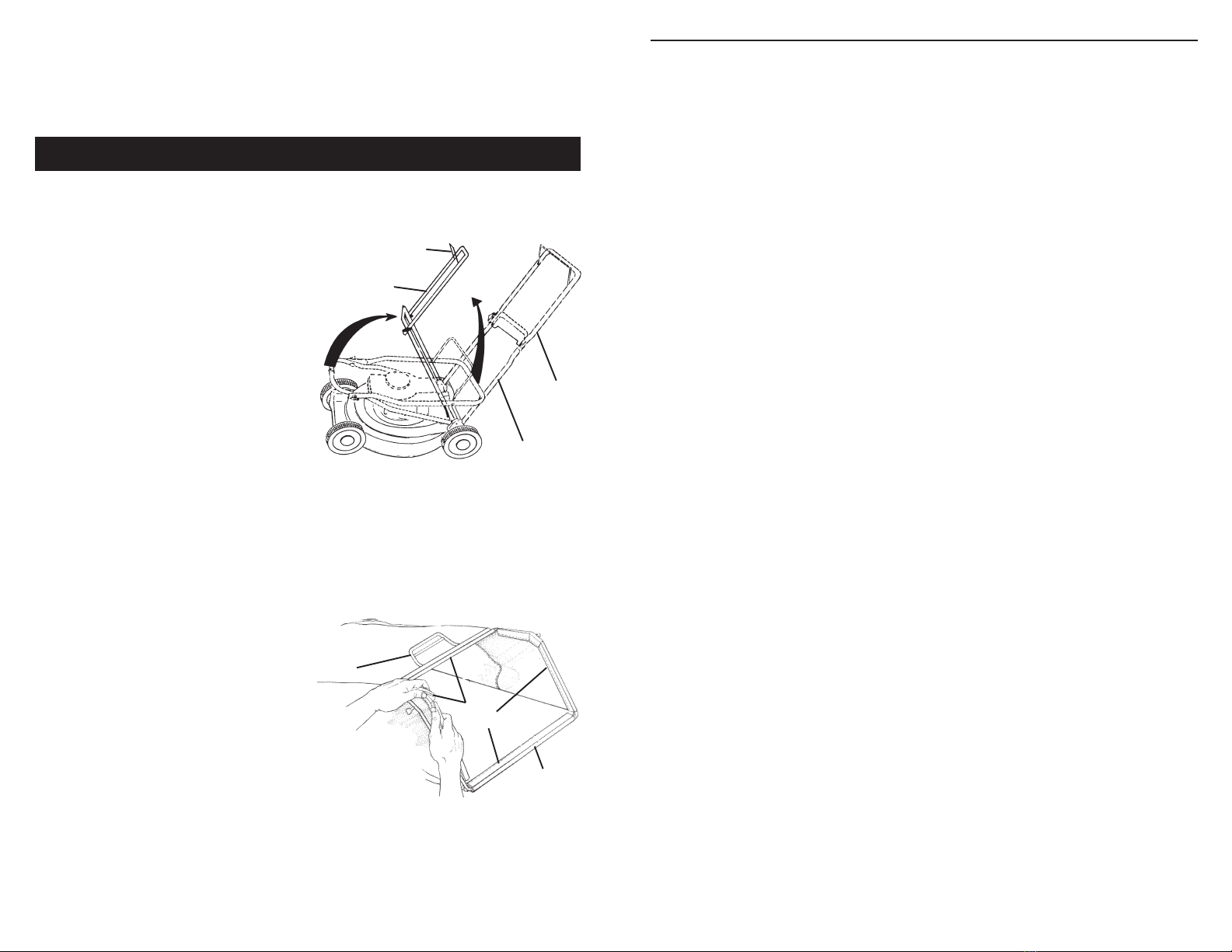
TO UNFOLD HANDLE
IMPORTANT: Unfold handles carefully so
as not to pinch or damage control cables.
1. Raise handles until lower handle
section locks into place in mowing
position.
2. Remove protective padding, raise
upper handle section into place on
lower handle and tighten both handle
knobs.
3. Remove handle padding holding
operator presence control bar to
upper handle.
TO ASSEMBLE GRASS CATCHER
1. Put grass catcher frame into grass bag
with rigid part of bag on the bottom.
Make sure the frame handle is outside
of the bag top.
2. Slip vinyl bindings over frame.
NOTE: If vinyl bindings are too stiff, hold
them in warm water for a few minutes. If
bag gets wet, let it dry before using.
TO INSTALL ATTACHMENTS
Your lawn mower was shipped ready to
be used as a mulcher. To convert to
bagging or discharging, see “TO CON-
VERT MOWER” in the Operation section
of this manual.
Your lawn mower handle can be adjusted
for your mowing comfort. Refer to
“ADJUST HANDLE” in the Service and
Adjustments section of this manual.
• Grass catcher components are subject
to wear, damage, and deterioration,
which could expose moving parts or
allow objects to be thrown. Frequently
check components and replace with
manufacturer’s recommended parts,
when necessary.
• Mower blades are sharp and can cut.
Wrap the blade(s) or wear gloves, and
use extra caution when servicing them.
• Do not change the engine governor
setting or overspeed the engine.
Mowing
position
Lower handle
LIFT
UP
Operator presence
control bar
Upper handle LIFT UP
Catcher
frame
handle
Vinyl
bindings
Frame
opening
21
MODEL NUMBER GCV-160-A1AEHONDA 4-CYCLE ENGINE
CONTROL
KEY PART
NO. NO. DESCRIPTION
1 5580311 Arm, Governor
2 5580329 Rod, Governor
3 5580345 Spring, Governor
4 5580352 Spring, Throttle Return
5 4439428 Spring, Lever
6 0800466 Holder, Cable
7 5580378 Base Comp., Control (Use up to
Serial Number 1177559)
6094122 Base Comp., Control (Use from
Serial Number 1177560)
8 5580386 Rod, Choke
9 2418671 Bolt, Governor Arm
10 5580998 Bolt, Flange (6 x 45) (ct200)
11 0145557 Screw, Pan (5 x 16)
12 0471623 Nut, Flange, 6mm
CAMSHAFTPULLEY
KEY PART
NO. NO. DESCRIPTION
1 5580055 Pulley Comp., Camshaft
2 5580063 Shaft, Cam Pulley
3 5580071 Belt, Timing
4 5580089 Arm, Intake Valve Rocker
5 5580097 Arm, Exhaust Valve Rocker
6 5580105 Shaft Rocker Arm
7 5580113 Valve, Intake
8 5580121 Valve, Exhaust
9 5580139 Spring, Valve
10 1426980 Retainer, Intake Valve Spring
11 0294819 Screw, Tappet Adjuster
12 0004598 Nut, Tappet Adjuster
13 0018044 O-ring
13 2373447 O-ring
CARBURETOR
KEY PART
NO. NO. DESCRIPTION
1 3088416 Gasket Set
2 5580162 Float Set
3 4930756 Chamber Set, Float
4 4481818 Screw Set
5 1441518 Screw Set
6 5580170 Screw Set
7 5664552 Carburetor Assembly
8 5580212 Valve Float
9 5580220 Nozzle Main
10 5580238 Insulator, Carburetor
11 5580246 Gasket, Insulator
12 4581120 Gasket, Carburetor
13 5580253 Gasket, Carburetor
14 5580535 Guide Comp., Air
15 0639419 Screw, Pan (5 x 6)
15 3344520 Screw, Pan (5 x 6)
16 0635474 Jet, Main #60 (optional)
16 0635482 Jet, Main #62 (optional)
16 0636126 Jet, Main #65 (optional)
FANCOVER
KEY PART
NO. NO. DESCRIPTION
1 3683646 Rubber, Supporter, 107 mm
2 5028923 Petcock Assembly, Manual
3 5580394 Bracket, Petcock
4 5580451 Cap Assembly, Fuel Tank
5 5580469 Tube, Fuel
6 5580519 Cover Comp., Fan, NH1, Black
7 5580527 Coller, Fan Cover
8 2499440 Collar, Front Turn Signal
9 5581004 Bolt, Stud
10 0671636 Screw, Washer, 5 x 10
11 2449593 Bulk Hose, Fuel
12 0250647 Clip, Tube (B8)
13 0250985 Clip, Tube (B10)
14 0053447 Clip, Tube (C9)
FLYWHEEL
KEY PART
NO. NO. DESCRIPTION
1 0348433 Key, Special Woodruff (25 x 18)
2 5580659 Coil Assembly, Ignition
3 5723747 Flywheel Assembly
4 5580675 Wire, Stop Switch
5 5580683 Switch Assembly, Engine Stop
6 5580782 Brake Assembly
7 5580790 Spring, Brake Lever
8 0803619 Bolt Flange (6 x 14)
9 1725050 Bolt, Flange (6 x 23)
10 0671552 Bolt, Flange (6 x 20)
11 0442038 Nut, Special, 14mm
12 1824630 Clip Cable
13 0485946 Screw, Washer (4 x 12)
14 1510361 Washer, Plain