Cranborne Audio 500ADAT User manual

Congratulations on your purchase of 500ADAT and thank you for selecting Cranborne Audio to
be a part of your music creation process.
What we set out to achieve with 500ADAT was putting control back into the hands of
musicians and engineers. In a sea of products that rely on computer integration and a “virtual
emulation” mentality, we set out to offer an alternative that places a true, customisable, and
flexible analogue front-end at the forefront of music creation - after all, the feel and touch of a
musician is analogue and that’s where the music begins.
Working in harmony with 500ADAT’s analogue stages is its high-performance digital stages.
Each and every component inside 500ADAT has been carefully considered to ensure that every
nuance of your 500 series module is translated into the best possible digital signal to be
processed. We employ converters with specifications that rival that of the best standalone
units whilst being governed by our master reference-grade clock featuring less than 0.5
picoseconds of jitter.
Cranborne Audio, for us, means so much more than metal boxes with components in them.
These are our labours of love that embody and demonstrate our demand for excellence. By
distilling what matters and putting our soul into these tools, we hope to help other people
make magic and express themselves, and in some way, become part of our Cranborne Audio
family.
So welcome to our family. We care for our family. And we care about making your tracks,
albums, scores sound as good as they should.
500ADAT Quick Start Guide Rev02 -Page 1- ©2021 Cranborne Audio Ltd

500ADAT Quick Start Guide
500ADAT Quick Start Guide 2
Controls and Connectors 3
Package Contents 5
Rack Ear Orientations 5
Powering Procedures 6
Powering On 6
Powering Off 6
Installing and Removing 500 Series Modules 6
Installing Modules 6
Removing Modules 6
Hardware Setup 7
Configuring Clock Source 8
Configuring Sample Rate 9
ADAT, SMUX II, & SMUX IV 9
Safety Information 10
General Safety 10
Installation notes 10
Power Safety 11
CE Certification 11
FCC Certification 11
RoHS Notice 12
Instructions for disposal of WEEE by end users in the European Union 12
Electromagnetic Compatibility 12
Environmental 12
Please download the full User Manual from the 500ADAT product
page on the Cranborne Audio website
www.cranborne-audio.com
500ADAT Quick Start Guide Rev02 -Page 2- ©2021 Cranborne Audio Ltd

Controls and Connectors
[1] Source Switch: Toggles the input source of
each 500 series slot between C.A.S.T., Analogue,
and ADAT sources.
[6] Aux 1 & 2 Blend Controls: Blends the
Summing Mixer and Aux Input together into the
Aux 1 and 2 Busses independently.
[2] Mix Level & Pan Controls: Adjusts the level
and pan position of each 500 series slot into the
built-in Summing Mixer.
[7+8] Aux 1 & 2 Level Controls: Adjusts the main
level of Aux 1 and 2 to their discrete headphones
and Aux Output 1/4” jack outputs on the rear
panel.
[3] Chain Switch: Sends the output of the
preceding module into the input of the next. (1
into 2, 2 into 3, 3 into 4 etc).
[9] Aux 1 & 2 Headphones Outputs: Used for
connecting Independent headphones to Auxes 1
and 2.
[4] Slot Bypass Switch: Bypasses the 500 series
slot to enable recording without a module
installed. All other features function normally
when slot bypass is engaged.
[10] Stereo Link Jumper: Connects Pin 6
between two adjacent 500 series slots to enable
the Stereo Link feature of supporting modules.
Stereo Linking only available between modules
1-2, 3-4, 5-6, and 7-8.
[5] Power Switch: Safely powers on and off
500ADAT as well as any inserted 500 series
module. Tap to power on, press and hold to power
off.
500ADAT Quick Start Guide Rev02 -Page 3- ©2021 Cranborne Audio Ltd
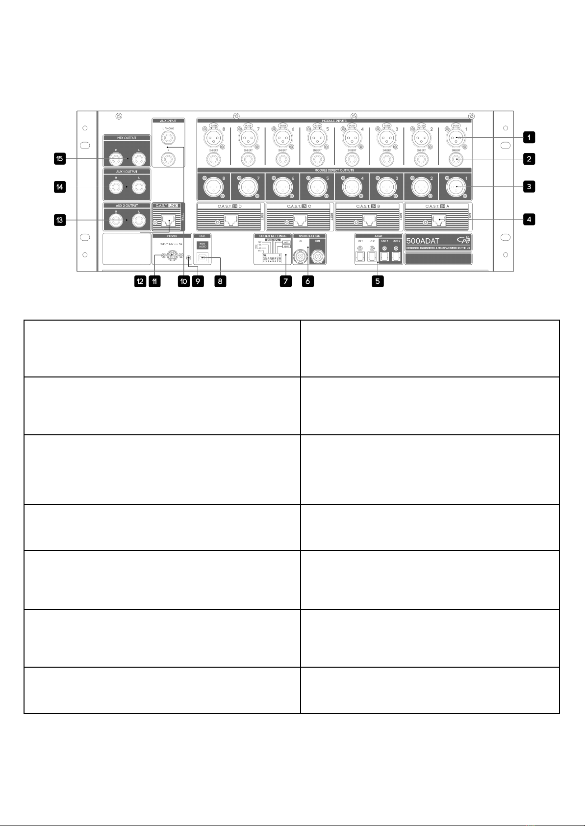
[1] Module Input: Connects balanced XLR analogue
inputs into each 500 series slot. Input sensitivity varies
depending on the type of module inserted.
[8] USB 2.0: Used for software updating and
non-audio purposes only. Cannot be used as an
audio interface.
[2] Insert: Connects external equipment in-line after
the 500 series module but before the A/D of each 500
series slot. Utilises a standard Y-split or insert cable.
(Tip=send, Ring=return).
[9] Grounding Post: Enables direct binding to
chassis ground to help eliminate ground loops in
specific setups.
[3] Module Direct Outputs: Sends balanced, line-level
outputs of each 500 series slot for connection to
external converters and equipment. Module Direct
Outputs are positioned post-insert point, pre Mix
Level.
[10] Aux Input: Connects analogue playback
sources from external audio interfaces directly
into 500ADAT’s monitoring paths.
[4] C.A.S.T. A, B, C, & D Inputs: Enables I/O relocation
and expansion via Cranborne Audio C.A.S.T. enabled
breakout boxes.
[11] Power: Provides 500ADAT with power via the
provided external 24v 5A DC power supply. No
other power supply should be used.
[5] ADAT I/O: Interfaces 500ADAT’s 8-in/8-out ADAT
optical lightpipe channels directly into your audio
interface of choice.
[12] C.A.S.T. Link: Enables linking of the Summing
Mixers between 500ADAT and a 500R8. C.A.S.T.
link transmits the Summing Mixer into the
connected 500R8 for monitoring.
[6] Word Clock I/O: Enables sending and/or receiving
word clock information to/from external digital
devices.
[13+14] Aux 1 & 2 Outputs: Connects balanced line
outputs of 500ADAT’s Aux 1 and 2 Busses to
external monitoring devices or similar via 1/4”
jacks.
[10] Clock Settings: Adjusts 500ADAT’s Clock Settings
including Clock Source and Sample Rate.
[15] Mix Output: Connects line outputs of
500ADAT’s built-in Summing Mixer directly to
external converters or similar via 1/4” jacks.
500ADAT Quick Start Guide Rev02 -Page 4- ©2021 Cranborne Audio Ltd

Package Contents
So now your 500ADAT is out of it’s packaging, you’re probably itching to get it powered on and
making music! But before you get started, please read the sections below that will help guide
you through the process of getting 500ADAT setup, plugged in, and ready-to-record as quickly
as possible!
The following items can be found in the packaging alongside 500ADAT:
- External power adapter
- IEC cable
- 16 module fixing screws (crosshead, 4-40 thread size)
- Allen key (2.5mm)
- Quickstart Guide
Rack Ear Orientations
There’s more to 500ADAT’s rack ears than meets the eye. 500ADAT’s rack ears can be
repositioned in 3 ways to suit particular applications and offer greater protection during
transport.
Standard - Standard rack ear configuration where the rack ears are mounted flush to
the front panel of 500ADAT.
Recessed - Protective rack ear configuration where 500ADAT is set backwards into its
rack ears to protect front panel controls during travelling and location recording.
Handle - Portable rack ear configuration where 500ADAT’s rack ears are removed,
placed back-to-back, and attached to 500ADAT as a convenient carry-handle for
travelling.
Depending on your desired use case, you may need to reorientate the rack ears and position
the rubber feet to best suit your application by using the supplied 2.5mm allen key.
For more information regarding the rack ears and their possible orientations,
please read the full instructions in 500ADAT’s User Manual.
500ADAT Quick Start Guide Rev02 -Page 5- ©2021 Cranborne Audio Ltd

Powering Procedures
Powering On
First, make sure your speakers are switched off and any
headphones are disconnected. Briefly tap the power
button located on the top right of 500ADAT’s front
panel. The power icon will illuminate blue and you will
hear soft ‘clicking’ as 500ADAT’s internal relays actuate.
You may now switch on your external equipment
sequentially, leaving your speakers until last.
Powering Off
First, make sure your speakers are switched off and any
headphones are disconnected. Press and hold the power
button for approximately 3 seconds. The power icon will deluminate and you will hear the soft
‘clicking’ of the relays indicating that the unit has been powered off.
Note:
Please follow these safe powering sequences carefully in order to prevent any
unwanted pops and spikes causing damage to downstream audio components
including speakers and headphones.
Installing and Removing 500 Series Modules
Installing Modules
1. Ensure 500ADAT is powered off and the power connector has been removed. Wait 30
seconds before continuing.
2. Firmly touch the metal chassis of 500ADAT to discharge any built-up static electricity.
3. Carefully pick up your 500 series module and locate its conductive edge into the
backplane connector of 500ADAT.
4. Once located, push the module into place and secure the module into the rack using
the supplied 4-40 screws - be careful not to over tighten and strip the screw or thread.
Removing Modules
1. Ensure 500ADAT is powered off and the power connector has been removed. Wait 30
seconds before continuing.
2. Firmly touch the metal chassis of 500ADAT to discharge any built-up static electricity.
3. Remove the 4-40 module fixing screws and store them in a safe place for future use.
4. Firmly pull the 500 series module to release the module from the backplane connector
of 500ADAT and then carefully remove the module from the rack itself.
Note:
Removing or installing modules when any 500 series rack is powered on can
cause irreparable damage to the backplane connector, supporting circuitry,
and the 500 series module. Damage caused when “Hot Swapping” or
installing/removing modules whilst 500ADAT is powered on is not covered
under Cranborne Audio’s Warranty.
500ADAT Quick Start Guide Rev02 -Page 6- ©2021 Cranborne Audio Ltd
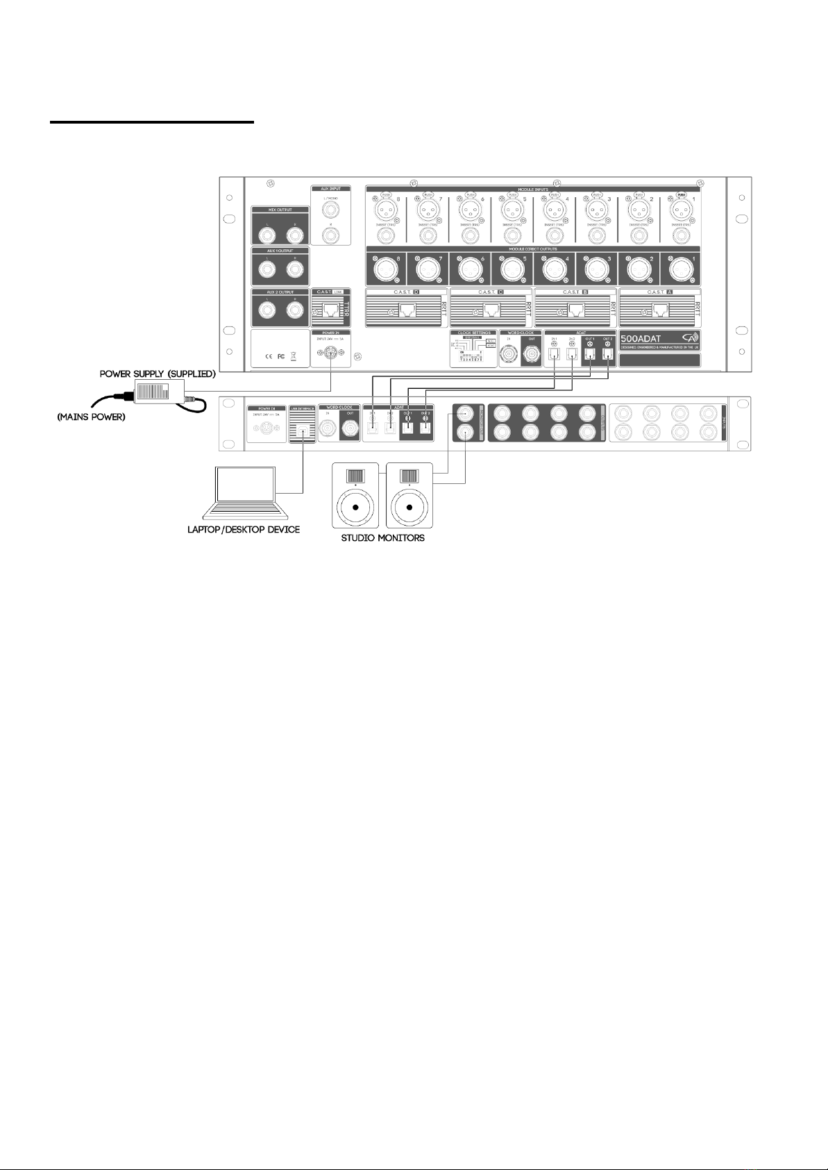
Hardware Setup
This hardware setup diagram will get 500ADAT connected to your audio interface and ready for
recording.
1) Connect mains power into the external PSU supplied in 500ADAT’s packaging and
connect the power connector into 500ADAT’s power inlet.
2) Connect 500ADAT to your audio interface using Optical Cables with Toslink connectors:
a) 500ADAT’s ADAT outputs should be connected to your audio interface’s ADAT
Inputs.
b) 500ADAT’s ADAT inputs should be connected to your audio interface’s ADAT
outputs.
2) Configure 500ADAT’s rear panel Clock Settings DIP switches:
a) Select your desired Sample Rate using DIP switches 1-4.
b) Configure DIP switch 5 into its UP/ON position.
c) All other DIP switches should be DOWN/OFF.
3) Power On 500ADAT using a brief tap of the Power button.
4) Configure your audio interface to clock from via ADAT and ensure your project’s Sample
Rate matches the Sample Rate set on 500ADAT’s Clock Settings DIP switch.
a) Consult the manufacturer of your audio interface for instructions on how to clock
externally via ADAT.
Note:
To achieve 500ADAT’s best performance, 500ADAT should be set as the clock
master of your system and the project sample rate should match 500ADAT’s.
500ADAT Quick Start Guide Rev02 -Page 7- ©2021 Cranborne Audio Ltd

Configuring Clock Source
500ADAT can be integrated into your studio as either a master or slave device by configuring
its Clock Settings DIP switches. These DIP switches allow for direct control over 500ADAT’s
internal clock and are divided into Sample Rate selection (switches 1-4) and Clock Source
selection (switches 5-8).
The clock source can be assigned to 3 different options to allow for maximum integration into
your studio space.
Internal Clock (default, recommended)
Configures 500ADAT to generate its own ultra-low
jitter clock. This setting should be used when
500ADAT is set as the clock master of your system.
This setting guarantees the best performance from
500ADAT’s converters.
Note:
When using 500ADAT as the clock master
and clocking using it’s Internal Clock, the
connected audio interface must be
configured to receive it’s clock via it’s
ADAT input.
Word Clock
Configures 500ADAT to slave from a device
connected to its Word Clock Input connector. This
setting should be used if you need 500ADAT to slave
off of your audio interface via word clock.
ADAT Recovered
Configures 500ADAT to slave from a device
connected to its ADAT IN 1 connector. This setting
should be used if you need 500ADAT to slave off of
your audio interface via ADAT.
Note:
Please take care to mute your ADAT connections on your audio interface
before configuring 500ADAT’s clock source as sync noises can be present on
the ADAT outputs when the recovery clock is reconfiguring and resyncing.
This process takes approximately 3-5 seconds.
If the Sample Rate selected on 500ADAT’s DIP switches does not match the
Sample Rate of the connected audio interface, 500ADAT’s ADAT outputs are
automatically muted until the Sample Rate is matched between 500ADAT
and the connected audio interface.
500ADAT Quick Start Guide Rev02 -Page 8- ©2021 Cranborne Audio Ltd

Configuring Sample Rate
The Clock Settings DIP switches are also used to assign 500ADAT’s operating Sample Rate. DIP
switches 1-4 can be configured in up to 6 ways to achieve the major Sample Rates from
44.1kHz to 192kHz. The Sample Rate selected on the Clock Settings DIP switches needs to
match the Sample Rate selected on the connected audio interface to prevent clocking errors,
dropouts, and audio artefacts.
Sample Rate
DIP switch
44.1kHz
48kHz
88.2kHz
96kHz
176.4kHz
192kHz
ADAT, SMUX II, & SMUX IV
500ADAT implements an in-depth integration of ADAT with SMUX II and IV to allow recording
at higher sample rates.
2 ADAT Input and 2 ADAT Output ports enable expansion of up to 8 channels at 44.1 to 96kHz,
or 4 channels at 176.4 to 192kHz.
The below table details the routing of ADAT I/O between the 4 ADAT ports and 500ADAT’s 500
series slots including the tradeoffs between high sample rates and the available I/O count:
Sample Rate
In 1
In 2
Out 1
Out 2
44.1/48kHz
Slot Input 1 - 8
N/A
Slot Output 1 - 8
N/A
88.2/96kHz
Slot Input 1 - 4
Slot Input 5 - 8
Slot Output 1 - 4
Slot Output 5 - 8
176.4/192kHz
Slot Input 1 - 2
Slot Input 3 - 4
Slot Output 1 - 2
Slot Output 3 - 4
Note:
In order to achieve the full channel count at the highest sample rates, the audio
interface connected to 500ADAT needs to be compatible with SMUX II and IV
protocols and both ADAT I/O ports need to be connected.
500ADAT Quick Start Guide Rev02 -Page 9- ©2021 Cranborne Audio Ltd

Safety Information
General Safety
- Read these instructions carefully
- Keep these instructions
- Heed all warnings
- Follow all instructions
- Do not use this apparatus near water
- Clean only with a dry cloth
- Do not block any ventilation openings and install in accordance with the manufacturer’s
instructions.
- Do not install near any heat sources such as radiators, heat registers, stoves or other
apparatus (including amplifiers) that produce heat.
- Do not defeat the safety purpose or grounding-type plug. A polarized plug has two
blades with one wider than the other. A grounding type plug has two blades with a third
grounding prong. The wide blade or the 3rd prong are provided for your safety. If the
provided plug does not fit your outlet, consult an electrician for replacement of the
obsolete outlet.
- Protect the power cord from being walked on or pinched particularly at plugs,
convenience receptacles, and the point where they exit from the apparatus.
- Only use attachments/accessories recommended by the manufacturer.
- Unplug this apparatus during lightning storms or when unused for long periods of time.
- Refer all servicing to qualified service personnel. Servicing is required when the
apparatus has been damaged in any way, such as power-supply cord or plug is
damaged, liquid has been spilled or objects have fallen into the apparatus, the
apparatus has been exposed to rain or moisture, does not operate normally, or has been
dropped.
- Do NOT modify this unit, altercations may affect performance, safety and/or
international compliance standards.
- Cranborne Audio does not accept liability for damage caused by maintenance, repair or
modification by unauthorized personnel.
Installation notes
- When installing the apparatus either fit it into a standard 19” rack or place it on a secure
level surface.
- If the unit is rack mounted, fit all rack screws.
- When rack mounting, allow a 1U gap above and below the unit for cooling.
- Ensure that no strain is placed on any cables connected to this apparatus. Ensure that all
such cables are not placed where they can be stepped on, pulled, or tripped over.
WARNING: To reduce the risk of fire or electric shock, do not expose this
apparatus to rain or moisture.
ATTENTION: Afin de réduire les risques de choc électrique, ne pas exposer
cet appareil à l’humidité ou à la pluie.
500ADAT Quick Start Guide Rev02 -Page 10- ©2021 Cranborne Audio Ltd
Power Safety
- The unit is supplied with an external power supply and suitable mains lead. Only use the
supplied external power supply, however if you decide to use a mains lead of your
choice, bear in mind the following:
- Refer to the rating label of the unit and always use a suitable mains cords.
- The unit should ALWAYS be earthed with the earth on the IEC socket.
- Please use compliant 60320 C13 TYPE SOCKET. When connecting to supply
outlets ensure that appropriate sized conductors and plugs are used to suit local
electrical requirements.
- Maximum cord length should be 4.5m (15’)
- The cord should bear the approval mark of the country it is to be used.
- Connect only to an AC power source that contains a protective earthing (PE) conductor.
- Only connect unit to single phase supplies with the neutral conductor at earth potential.
GB The apparatus shall be connected to mains socket outlets with a protective earthing
connection.
DEN Apparatets stikprop skal tilsluttes en stikkontakt med jord, som giver forbindelse til
stikproppens jord.
FIN Laite on lilettävä sojamaadoituskoskettimilla varustettuun pistorasiaan.
NOR Apparatet må tilkoples jordet stikkontakt.
SWE Apparaten skall anslutas till jordat uttag.
ATTENTION: Un-earthed metal parts may be present inside the enclosure. No
user serviceable parts inside - to be serviced only by qualified personnel.
When servicing, disconnect all power sources before removing any panels.
CE Certification
This unit is CE compliant. Note that any cables supplied with Cranborne Audio
equipment may be fitted with ferrite rings at each end. This is to comply with the
current regulations and these ferrites should not be removed.
FCC Certification
- Do not modify this unit! This product, when installed as indicated in the instructions
contained in the installation manual, meets FCC requirements.
- Important: this product satisfies FCC regulations when high quality shielded cables are
used to connect with other equipment. Failure to use high quality shielded cables or to
follow the installation instructions may cause magnetic interference appliances such as
radios televisions and will void your FCC authorisation to use this product in the USA.
- This equipment has been tested and found to comply with the limits for a Class B digital
device, pursuant to part 15 of FCC rules. These limits are designed to provide reasonable
protection against harmful interference when the equipment is operated in a
commercial environment. This equipment generates, uses, and can radiate radio
frequency energy and if not installed and used in accordance with the instruction
manual may cause harmful interference to radio communications. Operation of this
equipment in a residential area is likely to cause harmful interference in which case the
user will be required to correct the interference at their own expense.
500ADAT Quick Start Guide Rev02 -Page 11- ©2021 Cranborne Audio Ltd

RoHS Notice
Cranborne Audio complies with and this product conforms to European Union’s directive
2011/165/EU on Restrictions of Hazardous Substances (RoHS) as well as the following sections of
California law which refer to RoHS, namely sections 25214.10, 25214.10.2, and 58012, Health and
Safety Code Section 42475.2, Public Resources Code.
Instructions for disposal of WEEE by end users in the European Union
The symbol shown here, which is on the product or on its packaging indicates
that this product must not be disposed of with other waste. It is the user’s
responsibility to dispose of their waste equipment by handing it over to a
designated collection point for recycling waste electrical equipment and
electronic equipment. For more information about where you can drop off your
waste equipment for recycling, please contact your local city office, your
household waste disposal service or where you purchased the product.
WARNING: cancer and reproductive harm - www.P65Warnings.ca.gov
Evaluation of apparatus based on altitude not exceeding 2000m. There may be
some potential safety hazard if the apparatus is operated at altitude exceeding
2000m.
Evaluation of apparatus based on the temperate climate conditions only. There
may be some potential safety hazard if the apparatus is operated in tropical
climate conditions.
Electromagnetic Compatibility
EN 55032:2015, Class B, EN 55016-2-1:2009 A1 2011. EN 55016-2-3:2010 A1 2010, EN 55035:2017, EN
61000-4-2:2009, EN 61000-4-3:2006 A1 2008 A2 2010, EN 61000-4-4:2012, EN 61000-4-5:2014 A1
2017, EN 61000-4-6:2014, EN 6100-4-11:2004 A1 2017, EN 61000-3-2:2014, EN 61000-3-2:2013, FCC
Part 15B Class B, ANSI C63.4:2014, ICES-003 Issue 6: Class B
Audio input and output ports are screened cable ports and any connections to them should be
made using braid-screened cable and metal conductor shells in order to provide a low
impedance connection between the cable screen and the equipment.
WARNING: Operation of this equipment in a residential environment could cause radio
interference.
Environmental
- Operating Temperature:: +1 to 30 degrees Celsius.
- Storage: -20 to 50 degrees Celsius.
For more information and guidance, please read your devices’ User
Manual or visit the Cranborne Audio website:
www.cranborne-audio.com
500ADAT Quick Start Guide Rev02 -Page 12- ©2021 Cranborne Audio Ltd
Other manuals for 500ADAT
1
Table of contents
Other Cranborne Audio Music Mixer manuals


