Crary Bear Cat DL10 User manual

ENGLISH
570cc Briggs & Stratton®
P/N: 78449-00
Revision 20230223
Serial Range: N01312 - Current
Companion to P/N: 78506-00
BEARCATPRODUCTS.COM// 888.625.4520
OWNER’S MANUAL
© 2023, Crary®Industries, All rights reserved. Produced and printed in the U.S.A.
LIMITED WARRANTY
This warranty applies to all Crary®Bear Cat®Outdoor Power Equipment manufactured by Crary Industries, Inc. and
does not include gas engine or electric powered pressure washers under the Crary Bear Cat brand. See Crary Bear
Cat Pressure Washer Limited Warranty for complete warranty details on those products.
Crary Industries, Inc. warrants to the original owner each new Crary Bear Cat product to be free from defects in
material and workmanship, under normal use and service. The warranty shall extend, from date of purchase, three
years (U.S. and Canada only [two years outside U.S. and Canada]) for Consumer use of the product, one year for
Commercial applications and six months for Rental applications. Replacement parts and accessories are warranted
for 90 days from date of installation. Batteries for Inverters and Generators are warranted for 90 days from the date
of purchase.
“Consumer” de ned as:Complete unit for personal, residential, or non-income producing use.
“Commercial” de ned as:Complete unit for commercial, institutional, property management, agricultural,horticultural
or income producing use.
“Rental” de ned as: Complete unit for rental purposes to produce income.
The product is warranted to the original owner by either a completed warranty registration on le at Crary Industries,
Inc. and/or proof of sale. Warranty coverage begins on the date of purchase. The warranty registration can be
registered on-line by visiting bearcatproducts.com/Product-Support/Product-Registration.
In the event of a failure, return the product, at your cost, along with proof of purchase to the selling Crary Bear
Cat dealer. Crary Industries, Inc. will, at its option, repair or replace any parts found to be defective in material
or workmanship. Warranty on any repairs will not extend beyond the product warranty. Repair or attempted repair
by anyone other than an authorized Crary Bear Cat dealer as well as subsequent failure or damage that may occur
as a result of that work will not be paid under this warranty. Crary Industries, Inc. does not warrant replacement
components not manufactured or sold by Crary Industries, Inc.
1. This warranty applies only to parts or components that are defective in material or workmanship.
2. This warranty does not cover normal wear items including, but not limited to: batteries, bearings, belts,
pulleys, lters, chipper blades, shredder knives.
3. This warranty does not cover normal maintenance, service, or adjustments.
4. This warranty does not cover depreciation or damage due to misuse, negligence, accident, or
improper maintenance.
5. This warranty does not cover damage due to improper setup, installation, or adjustment.
6. This warranty does not cover damage due to unauthorized modi cations of the product.
7. Engines are warranted by the respective engine manufacturer and are not covered by this warranty.
Crary Industries, Inc. is not liable for any property damage, personal injury or death resulting from the unauthorized
modi cation or alteration of an Crary Bear Cat product or from the owner’s failure to assemble, install, maintain, or
operate the product in accordance with the provisions of the Owner’s manual.
Crary Industries, Inc. is not liable for indirect, incidental, or consequential damages or injuries including but not
limited to loss of crops, loss of pro ts, rental of substitute equipment or other commercial loss. This warranty gives
you speci c legal rights. You may have other rights that may vary from area to area.
Crary Industries, Inc. makes no warranties, representations or promises, expressed, or implied as to the performance
of its products other than those set forth in this warranty. Neither the dealer nor any other person has any authority
to make any representations, warranties or promises on behalf of Crary Industries, Inc. or to modify the terms or
limitations of this warranty in any way. Crary Industries, Inc., at its discretion, may periodically offer limited, written
enhancements to this warranty.
CRARY INDUSTRIES, INC. RESERVES THE RIGHT TO CHANGE THE DESIGN AND/OR SPECIFICATIONS OF ITS
PRODUCTS AT ANY TIME WITHOUT OBLIGATION TO PREVIOUS PURCHASERS OF ITS PRODUCTS.
20210624
Before You Begin
HOW TO CONTACT Crary Bear Cat
ADDRESS PHONE E-MAIL HOURS
237 NW 12th Street
P.O. Box 849
West Fargo, ND 58078
888-625-4520
701-282-5520
Fax: 701-282-9522
sales@bearcatproducts.com
Monday - Friday
8 a.m. to 5 p.m.
Central Time
DEAR Crary Bear Cat®CUSTOMER
Thank you for purchasing an Crary Bear Cat product. The Crary Bear Cat line is designed, tested, and manufactured to give
years of dependable performance. To keep your machine operating at peak efciency, it is necessary to adjust it correctly and
make regular inspections. The following pages will assist you in the operation and maintenance of your machine. Please read
and understand this manual before operating your machine.
If you have any questions or comments about this manual, please call us toll-free at 888-625-4520.
If you have any questions or problems with your machine, please call or write your local authorized Crary Bear Cat dealer.
This document is based on information available at the time of its publication. Crary Bear Cat is continually making
improvements and developing new equipment. In doing so, we reserve the right to make changes or add improvements to our
product without obligation for equipment previously sold.
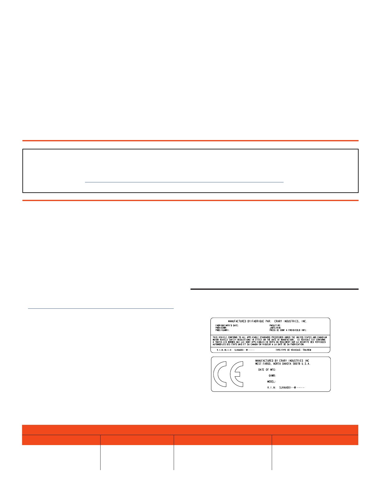
IDENTIFICATION NUMBER LOCATION
Your machine will have a vehicle identication number
(VIN). VINs are located on the left side of the trailer frame
near the hitch. They are 17-digit numbers of the format:
5VJAA001XXWXXXXXX. For the exact location of the VIN, see
the parts manual available at bearcatproducts.com/Product-
Support/Find-A-Product-Manual.
Record your identication number in the space provided.
VEHICLE IDENTIFICATION NUMBER
IMPORTANT WARRANTY REGISTRATION
IF YOU HAVE NOT REGISTERED YOUR CRARY BEAR CAT PRODUCT, PLEASE DO SO TODAY. TO REGISTER YOUR CRARY BEAR CAT
PRODUCT ON-LINE AT HTTPS://WWW.BEARCATPRODUCTS.COM/SUPPORT/PRODUCT-REGISTRATION/ OR CALL OUR CUSTOMER
SERVICE LINE AT (888) 625-4520 FOR ASSISTANCE IN REGISTRATION.
CARB Preemption Statement
Your Crary Industries (Crary) gasoline or diesel fueled
engine powered equipment (Equipment) is certied
and compliant to applicable U.S. Environmental Pro-
tection Agency (EPA) standards. Your Crary Equip-
ment matches an Equipment Type “preempted” from
California Air Resources Board (CARB) jurisdiction.
Farm and Construction equipment such as your Crary
Equipment is beyond CARB’s authority to regulate and
therefore subject only to EPA standards in the US,
including in California. Please reference the CARB
List to Determine Preempt Off-Road Applications on
http://www.arb.ca.gov/msprog/offroad/preempt.htm
for more information. As the owner, you must still fol-
low all engine and Equipment operating, maintenance
and repair instructions. Other local use or national
standards and registration requirements, such as the
CARB Portable Equipment Registration Program may
apply.

ENGLISH
LIMITED WARRANTY
This warranty applies to all Crary®Bear Cat®Outdoor Power Equipment manufactured by Crary Industries, Inc. and
does not include gas engine or electric powered pressure washers under the Crary Bear Cat brand. See Crary Bear
Cat Pressure Washer Limited Warranty for complete warranty details on those products.
Crary Industries, Inc. warrants to the original owner each new Crary Bear Cat product to be free from defects in
material and workmanship, under normal use and service. The warranty shall extend, from date of purchase, three
years (U.S. and Canada only [two years outside U.S. and Canada]) for Consumer use of the product, one year for
Commercial applications and six months for Rental applications. Replacement parts and accessories are warranted
for 90 days from date of installation. Batteries for Inverters and Generators are warranted for 90 days from the date
of purchase.
“Consumer” de ned as:Complete unit for personal, residential, or non-income producing use.
“Commercial” de ned as:Complete unit for commercial, institutional, property management, agricultural,horticultural
or income producing use.
“Rental” de ned as: Complete unit for rental purposes to produce income.
The product is warranted to the original owner by either a completed warranty registration on le at Crary Industries,
Inc. and/or proof of sale. Warranty coverage begins on the date of purchase. The warranty registration can be
registered on-line by visiting bearcatproducts.com/Product-Support/Product-Registration.
In the event of a failure, return the product, at your cost, along with proof of purchase to the selling Crary Bear
Cat dealer. Crary Industries, Inc. will, at its option, repair or replace any parts found to be defective in material
or workmanship. Warranty on any repairs will not extend beyond the product warranty. Repair or attempted repair
by anyone other than an authorized Crary Bear Cat dealer as well as subsequent failure or damage that may occur
as a result of that work will not be paid under this warranty. Crary Industries, Inc. does not warrant replacement
components not manufactured or sold by Crary Industries, Inc.
1. This warranty applies only to parts or components that are defective in material or workmanship.
2. This warranty does not cover normal wear items including, but not limited to: batteries, bearings, belts,
pulleys, lters, chipper blades, shredder knives.
3. This warranty does not cover normal maintenance, service, or adjustments.
4. This warranty does not cover depreciation or damage due to misuse, negligence, accident, or
improper maintenance.
5. This warranty does not cover damage due to improper setup, installation, or adjustment.
6. This warranty does not cover damage due to unauthorized modi cations of the product.
7. Engines are warranted by the respective engine manufacturer and are not covered by this warranty.
Crary Industries, Inc. is not liable for any property damage, personal injury or death resulting from the unauthorized
modi cation or alteration of an Crary Bear Cat product or from the owner’s failure to assemble, install, maintain, or
operate the product in accordance with the provisions of the Owner’s manual.
Crary Industries, Inc. is not liable for indirect, incidental, or consequential damages or injuries including but not
limited to loss of crops, loss of pro ts, rental of substitute equipment or other commercial loss. This warranty gives
you speci c legal rights. You may have other rights that may vary from area to area.
Crary Industries, Inc. makes no warranties, representations or promises, expressed, or implied as to the performance
of its products other than those set forth in this warranty. Neither the dealer nor any other person has any authority
to make any representations, warranties or promises on behalf of Crary Industries, Inc. or to modify the terms or
limitations of this warranty in any way. Crary Industries, Inc., at its discretion, may periodically offer limited, written
enhancements to this warranty.
CRARY INDUSTRIES, INC. RESERVES THE RIGHT TO CHANGE THE DESIGN AND/OR SPECIFICATIONS OF ITS
PRODUCTS AT ANY TIME WITHOUT OBLIGATION TO PREVIOUS PURCHASERS OF ITS PRODUCTS.
20210624

TABLE OF CONTENTS
1 SAFETY ................................................................................................................................................................... 1
1.1 SAFETY ALERT SYMBOL .................................................................................................................................................... 1
1.2 FIRE HAZARD INFORMATION............................................................................................................................................ 1
1.3 BEFORE OPERATING.......................................................................................................................................................... 1
1.4 OPERATION SAFETY........................................................................................................................................................... 2
1.5 MAINTENANCE/STORAGE SAFETY.................................................................................................................................. 2
1.6 SAFETY DECALS ................................................................................................................................................................. 3
1.7 SAFETY DECAL LOCATIONS ............................................................................................................................................. 4
2 ASSEMBLY.............................................................................................................................................................. 5
2.1 ATTACH VACUUM HOSE ..................................................................................................................................................... 5
2.2 ATTACH DISCHARGE TUBE ............................................................................................................................................... 6
2.3 ADD OIL TO ENGINE............................................................................................................................................................ 6
2.4 FILL THE FUEL TANK........................................................................................................................................................... 6
3 FEATURES & CONTROLS .................................................................................................................................... 7
4 OPERATION............................................................................................................................................................ 8
4.1 ATTACHING ........................................................................................................................................................................... 8
4.2 STARTING RECOIL MODELS ............................................................................................................................................. 8
4.3 STOPPING THE MACHINE.................................................................................................................................................. 8
4.4 VACUUMING OPERATION .................................................................................................................................................. 8
4.5 VACUUMING SAFETY & TIPS............................................................................................................................................. 8
4.6 TRANSPORTING .................................................................................................................................................................. 8
5 SERVICE & MAINTENANCE................................................................................................................................. 9
5.1 MAINTENANCE SCHEDULE ............................................................................................................................................... 9
5.2 CHANGE OIL ......................................................................................................................................................................... 9
5.3 REPLACING THE HOSE ...................................................................................................................................................... 9
5.4 REPLACING THE WEAR LINER ....................................................................................................................................... 10
5.5 CLEARING A PLUGGED FAN............................................................................................................................................ 10
5.6 CLEARING THE INLET HOSE........................................................................................................................................... 10
5.7 LUBRICATION ......................................................................................................................................................................11
6 TROUBLESHOOTING.......................................................................................................................................... 12
7 SPECIFICATIONS ................................................................................................................................................ 13
7.1 BOLT TORQUE.................................................................................................................................................................... 14
8 PARTS & OPTIONS.............................................................................................................................................. 15
8.1 REPLACEMENT PARTS..................................................................................................................................................... 15
8.2 OPTIONS ............................................................................................................................................................................. 15
1
ENGLISH
10 INCH VACUUM SHREDDER
Section
1 SAFETY
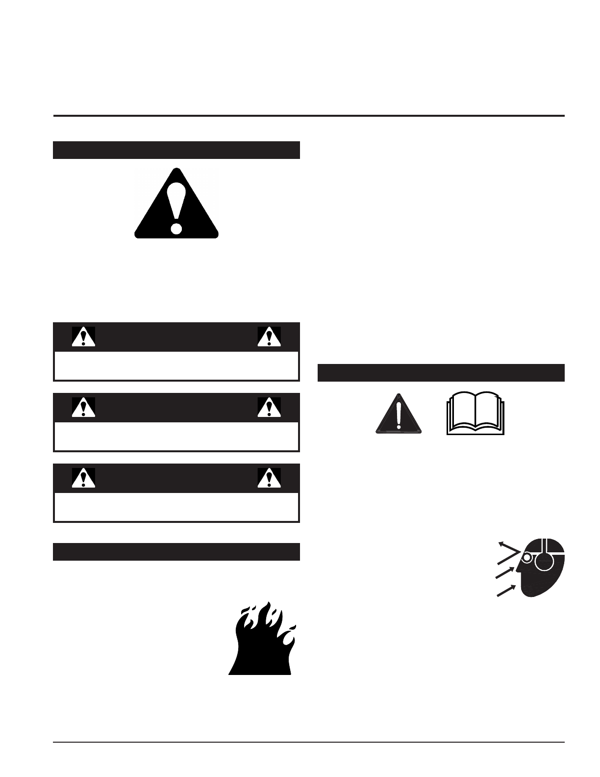
Indicates an imminently hazardous situation that, if not
avoided, will result in death or serious injury.
DANGER
1.1 SAFETY ALERT SYMBOL
Indicates a potentially hazardous situation that, if not
avoided, could result in death or serious injury.
WARNING
Indicates a potentially hazardous situation that, if not
avoided, may result in minor or moderate injury.
CAUTION
The Owner/Operator’s manual uses this symbol to alert
you of potential hazards. Whenever you see this symbol,
read and obey the safety message that follows it. Failure
to obey the safety message could result in personal injury,
death or property damage.
1. Read and understand this owner’s manual. Be
completely familiar with the controls and the proper
use of this equipment.
2. Familiarize yourself with all of the safety and
operating decals on this equipment and on any of its
attachments or accessories.
3. Keep safety decals clean and legible. Replace
missing or illegible safety decals.
4. Obtain and wear safety glasses
and use hearing protection at all
times when operating this machine.
5. Avoid wearing loose tted clothing.
Never operate this machine while wearing clothing
with drawstrings that could wrap around or get caught
in the machine.
6. Do not operate this machine if you are under the
inuence of alcohol, medications, or substances that
can aect your vision, balance or judgement. Do not
operate if tired or ill. You must be in good health to
operate this machine safely.
Federal, state, and local laws may prohibit the operation
of an internal combustion engine using hydrocarbon
fuels on any forest covered, brush
covered or grass covered land or on
land covered with grain, hay or other
ammable agricultural crops, without
an engine spark arrestor in continuous
eective working order.
The engine on your power equipment,
like most outdoor power equipment,
is an internal combustion engine that burns gasoline
or diesel fuel (hydrocarbons). If operating your power
1.2 FIRE HAZARD INFORMATION
equipment in aected areas, it must be equipped with a
spark arrestor in continuous eective working order. The
spark arrestor must be attached to the engine exhaust
system in such a manner that ames or heat from the
system will not ignite ammable material.
Failure of the owner/operator of the equipment to comply
with federal, state, and local laws may subject him or her
to nes and/or other penalties. Contact your local re
marshal or forest service for specic information about
which regulations apply in your area.
The standard muer installed on the engine is spark
arrestor capable. Spark arrestors require regular
maintenance. See the Service & Maintenance section of
this manual for more information.
Contact local re authorities for laws or regulations
regarding re prevention requirements.
1.3 BEFORE OPERATING

210 INCH VACUUM SHREDDER
SAFETY
1.4 OPERATION SAFETY
7. Do not operate this equipment in the vicinity of
bystanders. Keep the area of
operation clear of all persons,
particularly small children. It is
recommended that bystanders
keep at least 50 feet (15 meters)
away from the area of operation.
8. Do not allow children to operate this equipment.
9. Use only in daylight or good articial light.
10. Do not run this equipment in an enclosed area. Engine
exhaust contains carbon monoxide gas, a deadly
poison that is odorless, colorless and tasteless.
Do not operate this equipment in or near buildings,
windows or air conditioners.
11. Always use an approved fuel container. Do not
remove gas cap or add fuel when engine is running.
Add fuel to a cool engine only.
12. Do not ll fuel tank indoors. Keep open ames, sparks,
smoking materials and other sources of combustion
away from fuel.
13. Do not operate machine without shields in place.
Failure to do so may cause serious injury or death.
14. Keep all guards, deectors, and shields in good
working condition.
15. Before inspecting or servicing any part of this machine,
shut o the machine and make sure all moving parts
have come to a complete stop. Disconnect the battery
and remove the ignition key where applicable.
16. Check that all screws, nuts, bolts, and other fasteners
are secured, tightened and in proper working condition
before starting the machine.
17. Do not transport or move machine while it is operating
or running.
1. Always stand clear of discharge area when operating
this machine. Keep face and body away from feed
and discharge openings.
2. Keep hands and feet out of feed and discharge
openings while machine is operating to avoid serious
personal injury. Stop and allow
machine to come to a complete
stop before clearing obstructions.
3. Set up your work site so you are
not endangering trac and the
public. Take great care to provide
adequate warnings.
4. Do not climb on machine when operating. Keep
proper balance and footing at all times.
1. Before inspecting, servicing, storing, or changing
an accessory, shut o the machine and make sure
all moving parts have come to a complete stop.
Disconnect the battery and remove the ignition key
where applicable.
2. Replace any missing or unreadable safety decals.
Refer to the safety decal section for part numbers.
3. Allow machine to cool before storing in an enclosure.
4. Store the machine out of reach of children and where
fuel vapors will not reach an open ame or spark.
5. Check rotor housing to verify it is empty before
starting the machine.
6. The fan will continue to rotate after being disengaged.
Shut o the machine and make sure all moving parts
have come to a complete stop before inspecting or
servicing any part of the machine. Disconnect the
battery and remove the ignition key if applicable.
7. When feeding material into machine, do not allow
metal, rocks, bottles, cans or any other foreign
material to be fed into the machine.
8. Ensure debris does not blow into trac, parked cars,
or pedestrians.
9. Keep the machine clear of debris and other
accumulations.
10. Do not allow processed material to build up in the
discharge area. This may prevent proper discharge
and can result in kickback of material through the
feed opening.
11. If the machine becomes clogged, the rotor strikes
any foreign object, or the machine starts vibrating
or making an unusual noise, shut o machine
immediately and make sure all moving parts have
come to a complete stop. Disconnect the battery
and remove the ignition key if applicable. After the
machine stops: A) Inspect for damage, B) Replace
or repair any damaged parts, and C) Check for and
tighten any loose parts.
12. On electric start models, disconnect cables from
battery before doing any inspection or service.
Remove key.
13. Check rotor hub bolts for proper torque after every
8 hours of operation. Check rotor integrity every 8
hours of operation. Failure to do so may cause poor
performance, damage or personal injury and will void
the machine warranty.
1.5 MAINTENANCE/STORAGE SAFETY

3
ENGLISH
10 INCH VACUUM SHREDDER
SAFETY
1.6 SAFETY DECALS
Read and understand this owner/
operators manual. Be completely
familiar with the controls and the proper
use of this equipment
Obtain and wear safety glasses and
use hearing protection at all times when
operating this machine.
Before inspecting or servicing any part
of this machine, shut o power source,
remove the key, disconnect spark plug
wire from spark plug and make sure all
moving parts have come to a complete
stop.
Do not operate this equipment in the
vicinity of bystanders. Do not allow
children to operate this equipment.
Always stand clear of discharge area
when operating this machine. Keep face and body away from discharge
areas.
Read and understand your owners manual before operating. If owners
manual was not included or you have any questions, please call
800.247.7335 or 701.282.5520 (U.S.A.).
Do not remove cover unless key is removed and all moving parts have
stopped. Use access for cleanout or inspection only. Do not operate
machine with access cover removed.
See Section 1.7 for decal locations. Familiarize yourself with all of the safety and operating decals on the machine
and the associated hazards. See the engine owner’s manual or contact the engine manufacturer for engine safety
instructions and decals.
1
3
2
4
6
PN 12172
PN 12173
Keep hands and any other body part out of the fan housing while
machine is operating to avoid serious injury or death. Stop and allow
machine to come to a complete stop before clearing obstructions.
PN 18993-00
PN 14942-00
PN 36176-00
Operation of this equipment may create
sparks that can start res around dry
vegetation. A spark arrestor may be
required. The operator should contact
local re agencies for laws or regulations
relating to re prevention requirements.
5PN 33883-00
33883-00
WARNING
ADVERTENCIA
OPERATION OF THIS EQUIPMENT MAY CREATE SPARKS
THAT CAN START FIRES AROUND DRY VEGETATION. A
SPARK ARRESTOR MAY BE REQUIRED. THE OPERATOR
SHOULD CONTACT LOCAL FIRE AGENCIES FOR LAWS
OR REGULATIONS RELATING TO FIRE PREVENTION
REQUIREMENTS.
EL USO DE ESTE EQUIPO PUEDE CREAR CHISPAS
CAPACES DE INICIAR INCENDIOS EN VEGETACION
SECA. PODRIA SE NECESARIO USAR UN PARACHISPAS.
EL OPERADOR DEBERA COMUNICARSE CON CUERPOS
DE BOMBEROS LOCALES PARA INFORMARSE DE LEYES
O REGLAMENTOS RELACIONADOS CON LOS
REQUISITOS EXIGIDOS PARA LA PREVENCION DE
INCENDIOS.
5. Never store this machine with fuel in the fuel tank inside a building where fumes may be ignited by an open ame or
spark. Ignition sources can be hot water and space heaters, furnaces, clothes dryers, stoves, electric motors, etc.
6. Drain the fuel and dispose of it in a safe manner for storage periods of three months or more.
410 INCH VACUUM SHREDDER
SAFETY
1.7 SAFETY DECAL LOCATIONS
The numbers below correspond to the decals in Section 1.6. Make certain that all safety and operating decals on this
machine are kept clean and in good condition. Decals that need replacement must be applied to their original locations.
3
1
5
4
6
2
5
ENGLISH
10 INCH VACUUM SHREDDER
Section
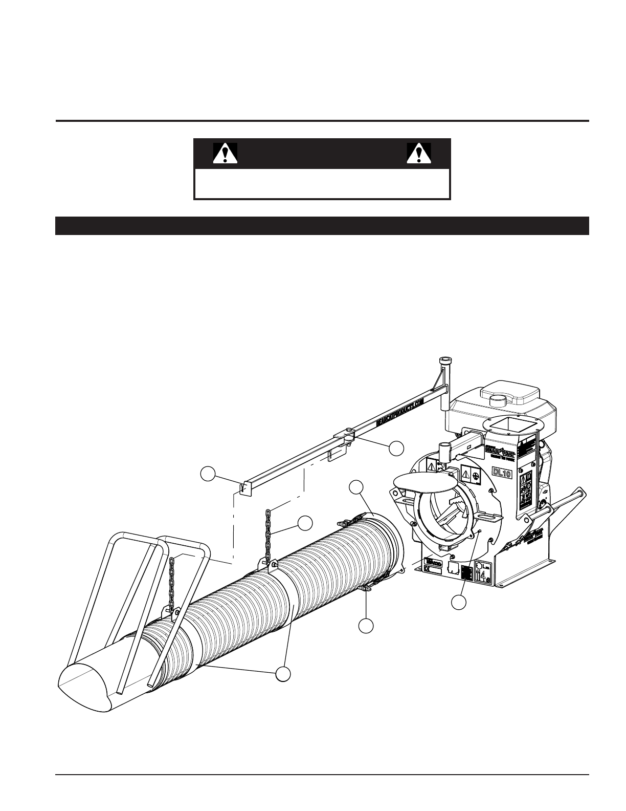
2 ASSEMBLY
1. Attach the hose assembly (1) to the fan intake weldment with the two provided knobs (2) and 5/16" × 3/4" carriage
bolts (3).
2. Insert the hose support (4) into the fan housing spacer.
3. It may be necessary to loosen the hose support clamps (7) to adjust their position to match the hooks of the hose
support (4).
4. Connect the hose to the hose support by hooking the chain links (5) into the hose support hooks (6).
2.1 ATTACH VACUUM HOSE
If any bolts or nuts are dropped in the machine, be
sure to remove them before starting the machine.
WARNING
4
6
1
7
7
5
3
2

610 INCH VACUUM SHREDDER
ASSEMBLY
1. Loosely assemble spacers (3) and one clamp (2)
to the discharge tube (5) using two knobs (4) and
carriage bolts (1).
2. Slide discharge assembly onto main assembly ange
and tighten knobs (4).
3. Install second clamp (2) using two knobs (4) and
carriage bolts (1).
4. To direct the discharge tube (5), loosen all four knobs
(4), reposition, and then retighten the knobs.
2.2 ATTACH DISCHARGE TUBE
Gasoline and diesel fuels are highly
ammable and their vapors are
explosive. To prevent personal injury or
property damage:
Store fuel only in approved containers,
in well ventilated, unoccupied buildings,
away from sparks or ames. A container
with a capacity of 2 gallons or less with
a pouring spout is recommended. Do
not ll the fuel tank while the engine is hot or running,
since spilled fuel could ignite if it comes in contact
with hot parts or sparks from ignition. Do not start the
engine near spilled fuel. Never use fuel as a cleaning
agent. DO NOT MIX OIL WITH FUEL.
WARNING
Use only those types of fuels that are recommended in
your engine owner’s manual.
To add fuel:
1. Stop engine, wait for all parts to stop moving and
disconnect spark plug wire. Remove key from key
switch. Allow the engine and muer to cool for at
least three minutes.
2. Clean area around fuel ll cap and remove cap.
3. Using a clean funnel, ll fuel tank to 1/2" below bottom
of ller neck to provide space for any fuel expansion.
Install fuel ll cap securely and wipe up any spilled
gasoline.
Check the oil level and, if needed, ll the engine crankcase
with the type and amount of oil specied in the engine
owner’s manual.
2.3 ADD OIL TO ENGINE
2.4 FILL THE FUEL TANK
5
3
2
1
4
3

7
ENGLISH
10 INCH VACUUM SHREDDER
Section
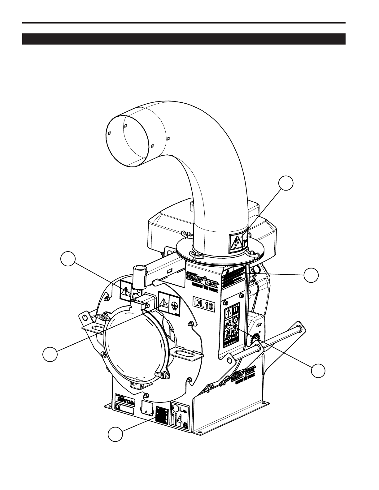
3 FEATURES & CONTROLS
3
2
1
6
4
5
Understanding how your machine works will help you achieve the best results when using your vacuum shredder. The
following descriptions dene the features and controls of your machine.
REFER TO ENGINE OWNER’S MANUAL FOR FURTHER ENGINE OPERATING INSTRUCTIONS.
1. DISCHARGE TUBE
2. ACCESS COVER
3. FUEL TANK
4. HOSE
5. HOSE HANDLE
6. HOSE SUPPORT

810 INCH VACUUM SHREDDER
Section
4 OPERATION
Move machine to a clear, level area outdoors before
starting. Do not operate in the vicinity of bystanders.
Make sure cutting chamber is empty before starting.
WARNING
Before operating your machine, be sure you read
and understand all safety, controls and operating
instructions in this owner’s manual and on your
machine. Failure to follow these instructions can result
in serious injury or property damage.
WARNING
4.1 ATTACHING
1. Attach to trailer/platform using holes in vacuum
shredder base.
2. A receiver bar kit is available for mounting to a
vehicle’s receiver hitch. See instructions included
with kit for attaching.
4.2 STARTING RECOIL MODELS
1. Check engine oil level before starting. Add oil if low,
but do not overll.
2. Make sure the hose inlet is free from debris.
3. Point the discharge tube in the correct direction.
4. Turn the fuel cut-o switch to ON.
5. Turn the engine switch to the ON position.
6. Move choke to the ON position. (If restarting a warm
engine, partial or no choke may be necessary.)
7. Move the throttle to between half and full throttle.
8. Pull the recoil starter until light resistance is felt. Then,
pull briskly. Make sure the starting cord retracts.
Repeat until engine starts.
9. Move the choke to the RUN position.
BE PREPARED. The hose inlet starts to vacuum
debris as soon as the engine starts.
DANGER
4.3 STOPPING THE MACHINE
1. Gradually move throttle to the slowest position.
2. Turn the engine switch to OFF.
3. If applicable, turn the fuel cut-o switch to OFF.
4.4 VACUUMING OPERATION
1. Run engine at full operating speed before starting to
vacuum.
2. Point the hose inlet towards the debris to be removed.
Use a sweeping motion to remove debris from a large
area.
4.5 VACUUMING SAFETY & TIPS
1. Keep hands or any other part of body or clothing away
from the hose inlet, discharge chute, or any moving
part.
2. Maintain proper balance and footing at all times.
3. Be careful when vacuuming around gravel, gardens,
lawn ornaments, etc.
4. Keep hose as straight as possible during operation in
order to prevent plugging.
5. Use a sweeping motion when vacuuming debris.
6. For maximum suction, keep nozzle close to debris,
but do not block air ow into the nozzle.
7. To extend hose life, periodically rotate the hose on
the fan housing and intake nozzle. This will promote
even wear on the hose.
4.6 TRANSPORTING
1. Turn o the machine and wait for all moving parts to
stop.
2. Remove the hose assembly by unscrewing the two
knobs that hold it to the fan housing. Store the hose
inside the towing vehicle so it will not drag on the
ground.
3. Obey road signs and limits.
10. Gradually move the choke lever to the OFF position
as the engine warms.
11. Gradually move the throttle to the full throttle position.
9
ENGLISH
10 INCH VACUUM SHREDDER
Section
5 SERVICE & MAINTENANCE
The items listed in this service and maintenance schedule
are to be checked, and if necessary, corrective action
taken. This schedule is designed for units operating under
normal conditions. If the unit is operating in adverse or
severe conditions, it may be necessary for the items to be
checked and serviced more frequently.
SEE ENGINE OWNER’S MANUAL FOR FURTHER
ENGINE MAINTENANCE AND TROUBLESHOOTING
INFORMATION.
SERVICE AND MAINTENANCE SCHEDULE
FREQUENCY
COMPONENT MAINTENANCE
REQUIRED
REFER TO ENGINE
OPERATOR’S MANUAL
BEFORE
EACH USE
EVERY 8
HOURS
EVERY
50 HOURS
Engine oil Change (1) ●
Fuel filter Replace ●
Spark plug Check condition and gap ●
Air filter element Clean (2) or replace ●
Engine oil Check/fill ●
All internal and external
nuts and bolts Check tightness ●
Air filter element Check ●
Spark arrestor* Clean ●
Entire machine Clean ●
(1) First hours of use.
(2) Perform more frequently when chipping dry or dirty wood.
*If equipped
5.1 MAINTENANCE SCHEDULE
Check the oil level before each use. If needed, ll the engine with the type and amount of oil specied in the engine
owner’s manual. Do not overll.
5.2 CHANGE OIL
Check the condition of the hose frequently. Replace if it is split or damaged.
1. Shut o engine and allow fan to completely stop.
2. Remove spark plug wire.
3. Remove the clamp attaching the hose to the hose intake weldment. Remove the hose from the intake weldment.
4. Remove two bolts from the hose wraps to separate the hose from the hose support.
5. Remove the remaining clamp securing the hose to the hose handle. Remove the hose from the hose handle.
6. Replace hose by performing steps 1-5 in reverse order.
5.3 REPLACING THE HOSE
To prevent personal injury or property damage: shut
o engine and make sure that all moving parts have
come to a complete stop before, servicing, adjusting or
repairing. Disconnect the battery and remove ignition
key where applicable.
WARNING

10 10 INCH VACUUM SHREDDER
SERVICE & MAINTENANCE
WARNING
BEFORE INSPECTING OR SERVICING ANY PART OF THIS MACHINE, SHUT OFF POWER SOURCE,
AND MAKE SURE ALL MOVING PARTS HAVE COME TO A COMPLETE STOP.
The fan housing wear liners are replaceable. To replace
the wear liners:
1. Shut o engine and allow fan to completely stop.
2. Remove the fan intake weldment from the fan housing.
3. Remove the 7/16" × 1-1/2" bolt and washer from the
end of the engine crank shaft.
4. Remove Cat Claws™ (SN: J03492 and above),
bushing and fan from the engine crank shaft.
5. From the outside of the vacuum shredder housing,
remove twelve 5/16" nylock nuts that hold the three
wear liners.
6. Remove the old wear liners and insert the new liners.
7. Install the new wear liners with twelve 5/16" × 3/4"
carriage bolts and nylock nuts. Feed the carriage
bolts from inside the vacuum shredder housing.
Torque hardware to 17 ft-lbs.
8. Reinstall Cat Claws (SN: J03492 and above), bushing
and fan on the engine crank shaft.
9. Reinstall the 7/16" × 1-1/2" bolt and washer to the
engine crank shaft. Torque to 50 ft-lbs.
10. Make sure approximately 1/4" clearance exists
between the fan housing and the fan plate.
5.4 REPLACING THE WEAR LINER
The vacuum shredder is designed to be used in fairly dry
conditions. Wet material, along with too much debris and
large sticks, can plug the fan or hose. A plugged fan bogs
down the engine and can possibly stop the engine if the
fan is severely plugged. To clear the fan:
1. Shut o engine and allow fan to completely stop.
2. Remove spark plug wire.
3. Loosen the six 5/16" nuts that hold the intake
weldment to the vacuum shredder frame.
4. Turn the vacuum intake counterclockwise to remove
it.
5. Check the hose for clogs and clear debris from the
fan.
6. Turn the fan by hand to verify it is unplugged.
7. Place the intake weldment over the six frame nuts
and turn it clockwise to set the studs in the weldment
notches. Tighten 5/16" nuts to 17 ft-lbs.
8. Reconnect spark plug wire and resume operation.
5.5 CLEARING A PLUGGED FAN
1. If the hose becomes plugged during operation,
straightening the hose may dislodge the clog.
2. If straightening the hose does not work, shake the
hose in an up and down or side to side motion.
3. If the clog remains after performing the above two
steps, shut the engine o and wait for all moving parts
to stop moving. Then, remove the hose from the fan
housing and manually unplug the hose.
5.6 CLEARING THE INLET HOSE

Visit https://qrco.de/CBCGreaseZerks to learn how to properly locate grease
points and grease your Crary Bear Cat machine for maintenance.

12 10 INCH VACUUM SHREDDER
Section
6 TROUBLESHOOTING
PROBLEM POSSIBLE CAUSES REMEDY
Engine will not start
Lack of fuel or oil Fill fuel tank and check oil level
Spark plug disconnected Connect spark plug
Kill switch on access cover is damaged Test kill switch. Replace if it is not working.
Dirty, stale, or contaminated fuel
Drain and refill fuel tank with fresh, clean
unleaded regular gasoline or diesel.
Replace fuel filter.
Internal engine problems See your engine dealer
Engine or fan stalls or
stops
Plugged fan Clear fan
Vacuuming material too quickly Slow vacuuming rate
Engine overheats
Cooling system plugged Clean cooling fan and cooling fins on the
radiator or engine block
Improper coolant level Fill engine to correct coolant level. Refer to
the engine owner’s manual.
Engine runs, but dies
or does not accelerate
properly
Air filter dirty Clean or replace
Fuel filter dirty Replace
Fuel vent plugged Clean or replace
Spark plug dirty/worn Clean and adjust or replace
Carburetor vibration Adjust
Cooling system dirty/plugged Clean
Spark arrestor* plugged Clean or replace
Fan will not turn Plugged fan Clear fan
Plugged discharge
tube
Engine speed too slow Increase engine speed
Vacuuming too much material into machine Slow vacuuming rate
Engine speeds up; will
not vacuum material Inlet hose is plugged Shake hose in an up and down or side to
side motion in order to dislodge debris
Before performing any of the corrections in this troubleshooting chart, refer to the appropriate information contained in
this manual for the correct safety precautions and operating or maintenance procedures. Contact your dealer or Crary
Bear Cat®for service problems with the machine.
*If equipped

13
ENGLISH
10 INCH VACUUM SHREDDER
Section
7 SPECIFICATIONS
DESCRIPTION ENGLISH METRIC
Engine Briggs & Stratton®Vanguard®570cc
Hose size 10" diameter × 12.5' 25.4 cm diameter × 3.8 m
Fan size 16.25" × 6.13" 41.3 cm × 15.6 cm
Discharge size 8" diameter 20.3 cm diameter
Discharge rotation 360 degrees
Maximum CFM (cubic ft./min) 3900
Drive type Shaft
Starter Electric
Mounting type Receiver hitch
Weight 340 lbs. 154 kg
Machine Dimensions (L × W × H) 42" × 30" × 57" 107 cm × 76 cm × 145 cm

14 10 INCH VACUUM SHREDDER
SPECIFICATIONS
The tables below are for reference purposes only and their use by anyone is entirely voluntary, unless otherwise noted.
Reliance on their content for any purpose is at the sole risk of that person and any loss or damage resulting from the
use of this information is the responsibility of that person.
7.1 BOLT TORQUE
*Torque value for bolts and capscrews are identied by their head markings.
Torque gures indicated above are valid for non-greased or non-oiled threads and heads unless otherwise specied. Therefore, do not grease or oil
bolts or capscrews unless otherwise specied in this manual. When using locking elements, increase torque values by 5%.
BOLT DIAMETER (A)
BOLT TORQUE*
SAE 2 SAE 5 SAE 8
NM FT-LB. NM FT-LB. NM FT-LB.
1/4" 7.5 5.5 11 8 16 12
5/16" 15 11 23 17 34 25
3/8" 27 20 41 30 61 45
7/16" 41 30 68 50 95 70
1/2" 68 50 102 75 149 110
9/16" 97 70 149 110 203 150
5/8" 122 90 203 150 312 230
3/4" 217 160 353 260 515 380
7/8" 230 170 542 400 814 600
1" 298 220 786 580 1220 900
1-1/8" 407 300 1085 800 1736 1280
1-1/4" 570 420 2631 1940 2468 1820
BOLT
DIAMETER (A)
BOLT TORQUE*
4.8 8.8 10.9 12.9
NM FT-LB. NM FT-LB. NM FT-LB. NM FT-LB.
M3 0.5 0.4 – – – – – –
M4 3 2.2 – – – – – –
M5 54––––––
M6 6 4.5 11 8.5 17 12 19 14.5
M8 15 11 28 20 40 30 47 35
M10 29 21 55 40 80 60 95 70
M12 50 37 95 70 140 105 165 120
M14 80 60 150 110 225 165 260 190
M16 125 92 240 175 350 255 400 300
M18 175 125 330 250 475 350 560 410
M20 240 180 475 350 675 500 800 580
M22 330 250 650 475 925 675 1075 800
M24 425 310 825 600 1150 850 1350 1000
M27 625 450 1200 875 1700 1250 2000 1500
15
ENGLISH
10 INCH VACUUM SHREDDER
Section
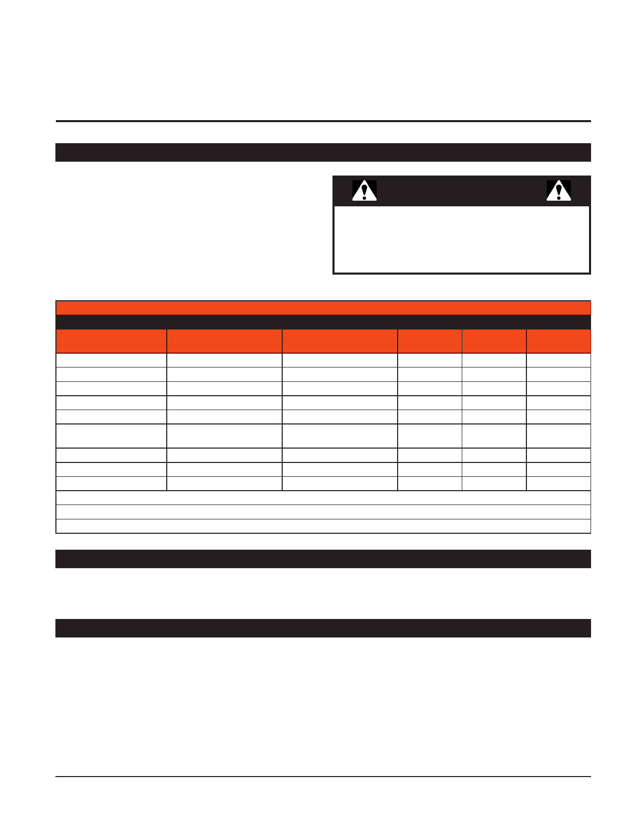
8 PARTS & OPTIONS
PART NUMBER DESCRIPTION
74737-00 KIT, HOSE AND CLAMP
75888-00 KIT, CHUTE EXTENSION
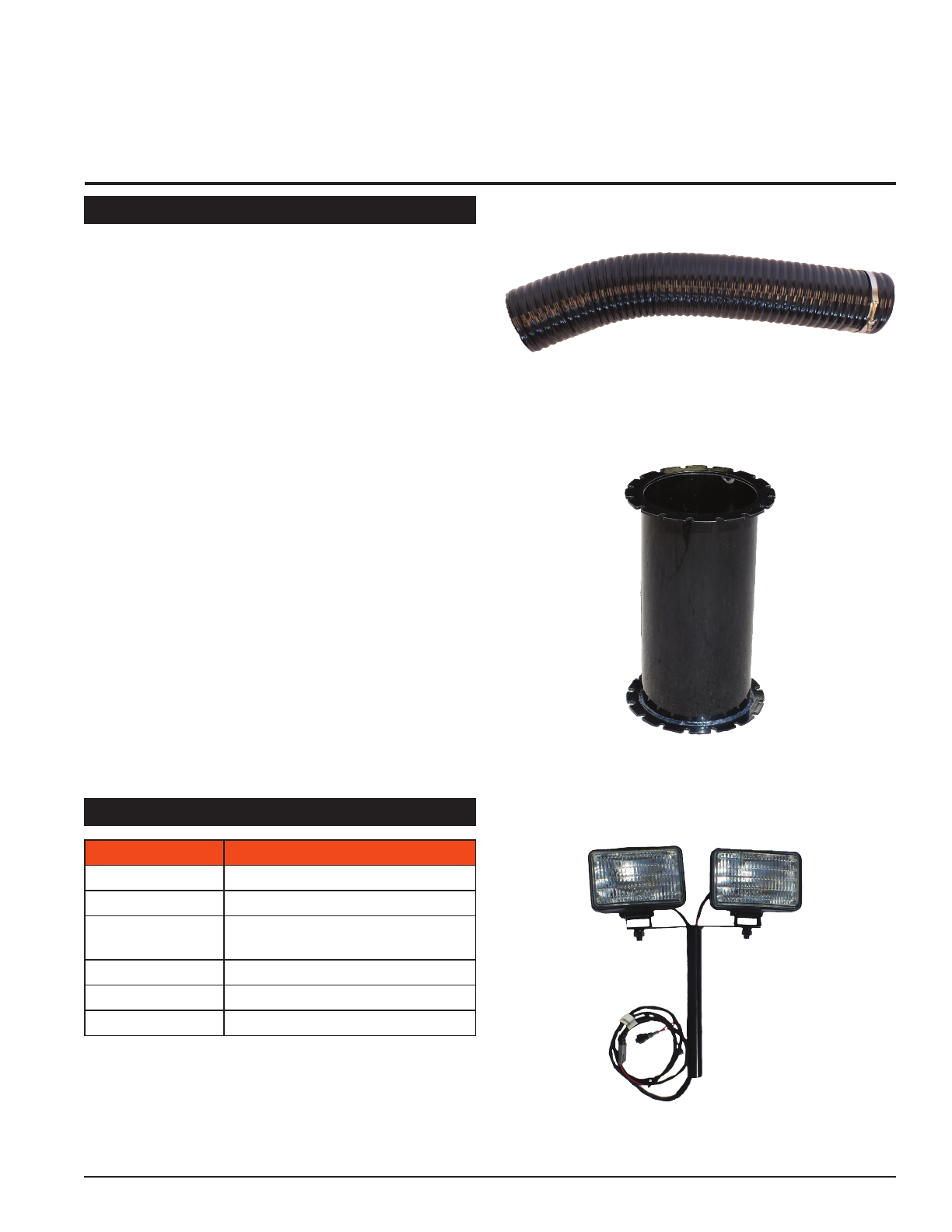
77105-00 KIT, VACUUM SHREDDER
LIGHTS
77398-00 KIT, LINER WEAR
77450-00 KIT, DEFLECTOR
77464-00 KIT, RECEIVER MOUNT
4' Flexible Horizontal Chute Extension, 74737-00
16" Vertical Chute Extension, 75888-00
FOR MACHINE SERVICE OR PARTS
For service assistance, contact your nearest authorized
Crary Bear Cat dealer or the factory. For parts, contact your
authorized dealer. The parts manual for your machine is
available at bearcatproducts.com/Product-Support/Find-
A-Product-Manual. Your dealer will need to know the serial
number of your machine to provide the most efcient
service. See below for information on how to identify and
record the serial number for your machine.
FOR ENGINE SERVICE OR PARTS
For engine service or parts, contact your nearest authorized
engine dealer. Crary Bear Cat does not handle any parts,
repairs or warranties for engines.
ORDERING PARTS
Only genuine Crary Bear Cat replacement parts should
be used to repair the machine. Replacement parts
manufactured by others could present safety hazards,
even though they may t on this machine. Replacement
parts are available from your Crary Bear Cat dealer.
Provide the following when ordering parts:
• The SERIAL NUMBER of your machine.
• The PART NUMBER of the part.
• The PART DESCRIPTION.
• The QUANTITY needed.
8.1 REPLACEMENT PARTS
8.2 OPTIONS
Lights Kit, 77105-00

Crary®Bear Cat®• 237 12th St. NW, West Fargo, ND 58078
For customer service or for your nearest Crary Bear Cat dealer call 888.625.4520 | For International call 701.282.5520
BEARCATPRODUCTS.COM
©2023 Crary Bear Cat, a subsidiary of Crary Incorporated. All Rights Reserved. Printed in the U.S.A
Table of contents


