Crate Quadradrive GT-200 Series User manual
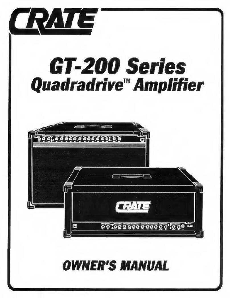
GT-200
Series
Quadradrive
™
Amplifier
OWNER'S
MANUAL

GT-200
Series
Quadradrive
Amplifier
You
aro
now
Ihe
proud
ownor
of
tho
one
of
the
newest
and
most
versatile
guitar
amplifiers
available,
tho
Crate
GT-200/200H
Quadradrive
™
.
This
flexible
and
compact
unit
features
four
separate,
footswitchable
Gain
controls,
with
your
choice
of
Tube
QR
Solid
State
preamps
for
either
the
Rhythm
OR
Lead
channels.
Discrete
tone.
Level,
and
Reverb
controls
for
each
channel
and
Crate's
exclusive
Tube
Driven
Mostet
power
amp
add
even
more
flexibility
and
control.
Like
all
Crate
products,
your
GT-200/200H
is
made
with
pride
in
America,
using
only
the
best
components.
Extensive
testing
at
the
hands
(and
ears)
of
skilled
technicians
and
musicians
insures
you
that
this
amplifier
is
the
absolute
best
it
can
be.
In
order
to
get
the
most
oul
of
your
new
amplifier,
we
strongly
urge
you
to
go
over
the
information
contained
in
this
manual
before
you
begin
playing.
And
thank
you
for
choosing
The
Crate
GT-200/200H
Quadradrive
™
is
truly
unique
and
versatile
With
four
separate
Gain
controls
(all
foot¬
switchable),
two
separate
channels
(footswitchable)
and
your
choice
of
tubes
or
solid
state
(also
footswitchable),
the
GT-200
gives
you
more
'sound
per
pound"
than
any
other
amp
of
its
kind.
Use
the
Solid
State
Rhythm
preamp
section
for
today's
sound;
crisp
highs
and
a
tight
bass
response.
Use
the
Tube
Rhythm
preamp
section
for
that
vintage
tube
sound,
from
ullra-clean
to
a
bluesy
crunch.
The
Solid
Slate
Lead
preamp
section
gives
you
all
of
the
traditional
Crate
Mega-Gain
hard
rock
sizzle
and
fire
with
lots
of
definition
and
compression.
And
the
Tube
Lead
preamp
section
starts
with
a
bluesy
crunch
and
can
deliver
everything
up
to
screaming,
tube-driven
lead
distortion
with
plenty
ol
sustain
and
to¬
tal
tone
conlrol.
FEATURES
OVERVIEW
Given
below
is
a
quick
overview
of
the
GT-200's
features
and
controls:
J
Two
Com
pletely
Sep
arate
Channels
:
Independent
Gains,
3
band
EG's,
Reverb
and
Levels.
V
Four
Gain
Control
s:
Tube
Lead.
Solid
state
Lead.
Tube
Rhythm.
Solid
state
Hhythm
V
Expander
Switch
:
Crate
original.
Creates
a
stereo-like
atmosphere
J
Truo
Storoo
Chorus
:
Dopth
and
Rate
controls.
Footswitchable.
J
Tube
Driven
Mosfet
Power
Amplifier
Crate
exclusive.
No
traditional
solid
state
output
devices.
No
chance
of
harsh
“square
wave"
distortion.
J
Total
Footswitch
Control
:
Channel
selection.
Tube
or
Solid
State
selection.
Chorus
orYoff
All
al
the
touch
ol
a
footswitch.
J
External
Speaker
Jack
:
Series
connection.
No
chance
of
overloading
the
amplifier.
Standard
1/4'
mono
phone
jack.
J
Effects
Loop
:
1/4"
Line
Out/Line
In
jacks.
Allows
external
signal
procossor
connection
Allows
diroct
connection
to
external
power
amplifier,
mixer,
recording
console
or
whatever.
2

GT-200
Series
Quadradrive
Amplifier

GT-200
Series
Quadradrive
Amplifier
THE
GT-200
FRONT
PAN
EL
1
334567
89
10
11
1?
U
14
15
16
17
18
19
30
21
22
24
25
26
27
28
1.
INPUT:
Connect
your
guilar
here
using
a
shieldec
instru-
ment
cable.
LEAD
SECTION
2:
TUBE
GAIN:
This
serves
as
the
gain
control
for
the
Lead
Channel's
Tube
preamo
section,
giving
you
control
over
the
compression
and
overdrive
characteristics
ol
the
GT-200's
irput
tubes.
Use
this
control
along
with
the
Lead
Channel's
Lovol
control
(#15)
to
create
a
wide
variety
ol
sounds
at
any
volume
level.
(Some
suggestec
sellings
can
be
found
on
page
7).
With
the
control
to
the
full-lef:
position,
no
signal
passes
through.
As
you
bring
the
control
towa-ds
center,
you
increase
the
signal
level
and
the
tube
compression,
with
maximum
tube
distortion
towards
the
full-right
position.
3.
LEAD
LED:
This
LED
glows
red
when
the
Lead
Channel
is
chosen,
and
along
with
LED
#14
gives
you
a
visual
sgn
that
the
Lead
Gains,
tone
section
and
Master
Level
are
active.
4.
SOLID
STATE
GAIN:
This
serves
as
the
gain
control
for
the
Lead
Channel's
Solid
State
preamp
section.
Use
this
control
along
with
the
Lead
Channel's
Level
control
(#15)
to
create
a
wide
variety
of
sounds
at
any
volume
level
(Some
suggestec
settings
can
oe
found
on
page
7).
With
the
control
to
the
full-left
position,
no
signal
passes
through.
As
you
b'ing
the
control
to¬
wards
center,
you
increase
the
signal
level
and
compression,
reaching
maximum
distortion
towards
the
full-right
position.
5.
CHANNEL:
Select
either
the
Lead
Channel
(switch
in
the
IN
position)
or
the
Rhythm
Channe
1
(switch
OUT)
with
this
push¬
button
switch.
The
channel
indicator
LEDs
(#3
4
14
for
Lead,
#9
&
19
for
Rhythm)
wo-k
with
this
switch
as
a
visual
guide.
NOTE:
When
a
footswiteh
is
connected
to
the
Channel
Select
footswitch
jack
(#36,
rear
panel)
the
front-panel
switch
will
have
no
control
over
which
preamp
section
»s
selected.
6.
TUBE7SOLID
STATE:
Select
either
the
Tube
preamp
(switch
IN)
or
the
Solid
State
preamp
(switch
OUT)
for
either
channel
with
this
pushbutton
switch.
The
Tube
LED
(#7)
works
wth
this
3witch
as
a
visual
guide:
it
glows
whon
tho
Tubo
soc
tion
has
been
seeded.
NOTE:
When
a
footswitch
is
connected
to
the
Channel
Select
footswitch
jack
(which
also
servos
as
the
Tubo/Solid
State
se¬
lect;
#36,
rear
panel)
the
front-panel
switch
will
have
no
control
over
which
preamp
sect
on
is
selected.
7.
TUBE
LED:
This
tube-shaped
symbol
glows
yollow
whon
the
Tube
preamp
section
is
selected,
giving
you
a
quick
visual
reference
as
to
which
preamp
section
s
active.
RHYTHM
SECTION
8.
TUBE
GAIN:
This
serves
as
the
gam
control
for
the
Rnythm
Channors
Tube
preamp
section,
giving
you
control
over
the
compression
ard
overdrive
characteristics
of
the
GT-20O‘s
preamp
tube
Use
Ihis
control
along
with
the
Rhythm
Channel's
Level
control
(#20)
to
create
a
wide
variety
of
sounds
at
any
vol¬
ume
level
(Some
suggested
settings
can
be
lound
on
page
7).
With
the
control
to
the
full-left
position,
no
signal
passes
through.
As
you
bring
tho
control
towards
center,
you
increase
the
signal
level
and
the
tube
compression,
with
a
bluesy
lube
crunch
coming
to
life
as
you
approach
a
setting
cf
’8'
and
thick¬
er
tube
d3tortion
in
tho
full-right
position.
9.
RHYTHM
LED:
Ths
LED
glows
green
when
the
Rhythm
Channel
is
chosen,
and
along
with
LED
#19,
gives
you
a
visual
sign
that
the
Rhythm
Channel
is
actve.
10.
SOLID
STATE
GAIN:
This
serves
as
the
gain
control
for
the
Rhythm
Channel's
Solid
Slate
prearrp
section.
Use
this
control
along
with
the
Rnythm
Channels
Level
control
(#20)
to
create
a
wide
variety
of
sounds
at
any
volume
level.
(Some
suggested
settings
can
be
found
on
page
7).
With
the
control
to
the
full-left
positicn.
no
signal
passes
through.
As
you
bnng
the
control
towards
center,
you
increase
the
signal
level,
which
stays
clean
all
the
way
up
to
the
full-right
position.
LEAD
CHANNEL
11.
LOW:
Adjust
the
Lead
ChannePs
fow
froquoncy
output
with
this
control:
the
center
position
is
'Hat;
that
is,
no
boost
or
cut.
By
turning
the
control
to
the
left
you
reduce
the
low
frequency
output,
turning
it
to
the
right
increases
the
ow
frequency
output.
The
Low
control
provides
up
to
12cB
ol
boost
or
cut
centered
at
100Hz.
12.
MID:
Adjust
the
Lead
Channel's
midrange
frequency
output
with
this
control:
in
the
center
position
the
midrange
output
is
■
flat’
(no
boost
or
cut).
Turning
the
control
to
the
left
reduces
the
midrange
output,
turning
i:
to
the
right
increases
the
mi¬
drange
output.
The
Mid
control
provides
up
to
5dB
of
boost
or
cut
centered
at
lOCOHz,
which
affects
the
Voice’
of
your
guitar’s
sound.
13.
HIGH:
Adjust
the
Lead
Channel's
high
frequency
output
with
this
control:
n
the
center
positon
the
high
frequency
output
will
be
‘flat’
(no
boost
or
cut).
Turning
the
control
to
the
left
re¬
duces
the
high
frequency
output;
lurning
it
to
the
right
increases
the
high
frequency
output.
The
High
control
provides
up
to
lOdB
of
boost
or
cui
centered
at
5000Hz,
which
allcws
you
to
adjust
the
crispness
or
the
'bite*
of
your
guitar
14.
LEAD
LED:
This
LED
glows
red
when
the
Lead
Channel
is
chosen,
and
along
with
LED
#3,
gives
you
a
visual
sign
that
;he
Lead
Gains,
tone
section,
and
Master
Leve
are
active
15.
LEVEL:
Adjust
the
output
level
cl
the
Lead
Channel
with
this
control:
in
the
full-left
position
there
is
no
output.
As
you
ro¬
tate
the
control
to
the
right
you
increase
the
strength
of
the
Lead
Channel's
signal
going
into
ihe
power
amp,
thus
increasng
the
output
volume.
The
signal
level
for
the
Lire
Cut
jack
(#34,
rear
panol)
is
simultaneously
affected
by
this
control.
RHYTHM
C
HANNEL
16.
LOW:
Adjust
the
Rhythm
Channel's
iow
frequency
output
with
this
control:
the
center
position
is
flat,"
that
is,
no
boosl
or
cui.
By
turning
the
control
to
the
left
you
reduce
the
low
fre¬
quency
output;
turning
il
to
the
right
increases
the
low
frequen¬
cy
output.
The
Low
control
provides
up
to
12dB
of
boost
or
cut
centered
at
100Hz.
17.
MID:
Adjust
the
Rhythm
Channel's
midrange
frequency
output
with
this
control:
in
the
center
positon
the
midrange
cut-
put
is
‘flat’
(no
boos:
or
cut).
Turning
the
control
to
the
left
re¬
duces
the
midrange
output;
turning
it
to
the
right
increases
the
midrange
output.
The
Mid
conirol
provides
up
to
7d3
o‘
boost
or
cut
centered
at
800Hz,
which
aftects
the
Voice'
of
your
gui¬
tar’s
sound.
4

GT-200
Series
Quadradrive
Amplifier
18.
HIGH:
Adjust
Ihe
Rhythm
Channel's
high
frequency
output
with
this
control:
in
the
center
position
the
high
frequency
ouiput
will
be
flat'
(no
boost
or
cut).
Turning
the
control
to
the
left
re¬
duces
the
high
frequency
output;
turning
it
to
the
right
increases
the
hgh
frequency
output.
The
High
control
provides
up
to
ISdBof
boost
or
cut
centered
at
ICkHz.
which
allows
you
toad-
just
the
crispness
or
the
‘bite’
of
your
guitar.
19.
RHYTHM
LED:
This
LED
glows
red
when
the
Rhythm
Channel
is
chosen,
and
along
with
LED
#9.
gives
you
a
visual
sign
that
the
Rhythm
Channel
is
active,
20.
LEVEL:
Adjust
the
output
level
of
the
Rhythm
Channel
with
this
control:
in
Ihe
full-left
position
there
is
no
output.
As
you
ro¬
tate
the
control
to
the
right
you
increase
the
strength
of
the
Rhythm
Channers
signal
going
into
ihe
power
amp,
thus
in¬
creasing
Ihe
output
volume
The
signal
level
fo>
the
Line
Out
jack
(#34.
rear
panel)
is
simultaneously
affected
by
this
control.
REVERB
SECTION
21.
LEAD:
Adjust
the
amount
ol
reverb
effect
for
the
Lead
Channel's
signal
with
this
control:
in
the
full-left
position
the
sig¬
nal
is
’dry'
(no
reverb).
As
you
rotate
the
control
to
the
right
you
increase
the
amount
of
reverberation,
with
maximum
reverb
ef¬
fect
achieved
at
the
lull-right
position.
22.
RHYTHM:
Adjust
the
amount
cf
reverb
effect
tor
the
Rhythm
Channel's
signal
with
this
control:
in
the
full-left
position
the
signal
is
'dry'
(no
reverb),
rotatng
the
control
to
the
right
in¬
creases
the
amount
of
reverberation.
CHORUS
SECTION
23.
CHORUS:
Select
Chorus
’ON*
(switch
n
the
IN
position)
with
this
pushbutton
switch.
The
Chorus
indicator
LED
(#27)
works
with
this
switch
as
a
visual
guide.
NOTE:
V/hen
a
footswitch
is
connected
to
the
Chorus
foot-
switch
jack
(#35,
rear
panel)
the
front-panel
switch
will
have
no
control
over
chorus
selection.
24.
EXPANDER:
With
this
switch
in
the
IN
position,
our
exclu¬
sive
Expander
circuitry
is
activated.
This
produces
the
effect
of
being
h
a
true
stereo
environment
with
speakers
on
either
side
of
you.
With
lhis
effect,
you
can
add
a
mere
‘roomy*
feeling
to
your
sound.
25.
EXPANDER
LED:
This
LED
glows
red
when
the
Expander
circuitry
is
selected,
giving
you
a
visual
indicator
that
it
is
active.
26.
DEPTH:
Set
the
intensity
of
the
stereo
chorus
effect
with
this
control:
in
the
far-left
posit
on
there
will
be
airiest
no
cho¬
rus;
as
you
rotate
the
control
to
the
right
the
amount
of
effect
increases.
27.
CHORUS
LED:
Ths
LED
glows
green
when
the
Chorus
section
is
selected
and
gives
you
a
visual
sign
that
the
Chorus
section
is
active.
28.
RATE:
Set
the
speed
of
the
stereo
chorus
effect
with
this
control:
to
the
left
for
slow,
smooch
‘phasing"
sounds,
to
the
right
fa
faster
'vibrato"
sounds.
29.
POWER:
This
hoavy-duty
rockor
typo
switch
is
usod
to
turn
the
amplifier
ON
in
the
left
position,
OFF
in
the
right
pcsi-
tion.
The
channel
LEDs
provide
a
visual
indicator
that
the
unit
Is
on.
THE
GT-200
REAR
PANEL
33
34
35
H
30.
FUSE:
This
protects
the
GT-200
against
damages
caused
trom
a
faulty
AC
power
source
or
other
problems,
if
the
fuse
blows,
replace
it
ONLY
with
tho
same
size
and
type
6A
slo-blo
fuse.
If
the
fuse
blows
repeatedly,
check
the
AC
source:
if
it’s
okay,
contact
your
Crate
dealer
lor
service
information.
31.
POWER
CORD:
Firmly
plug
the
supplied
heavy-duty,
grounded
power
cord
into
a
safely
wired,
grounded
120
volt,
60
cycle
AC
power
outlet.
DO
NOT
attempt
to
defeat
the
ground
connection
on
this
coblo.
If
your
G”-200
was
purchased
outside
of
ihe
United
States,
see
the
unit's
rear
panel
for
its
power
rating
and
follow
the
above
guidelines.
32.
EXTERNAL
SPEAKER
JACKS:
Allow
you
to
connect
the
output
of
the
GT-200
to
external
speakers,
placing
them
n
par¬
allel.
Any
load
equal
to
at
oast
4
ohms
may
bo
connected
to
these
speaker
jacks.
If
mere
fhar
one
jack
is
used,
the
total
load
impedarce,
considering
both
jacks,
must
be
at
least
4
ohms.
Tho
standard
internal
speaker
is
8
ohms.
An
additional
8
ohm
speaker
may
be
connected
here,
which
would
lotal
4
ohms.
With
the
GT-200H
(head),
you
may
coined
cne
4
ohm
speaker,
two
3
ohm
speakers,
or
four
16
ohm
speakers,
without
overloading
the
output.
33.
STEREO
EFFECTS
LOOP
LINE
IN:
Connecting
an
exter¬
nal
signal
processor,
such
as
digital
delay
or
echo,
can
be
accomplished
through
the
Line
In
and
Line
Out
jacks.
Connect
the
OUTPUT
of
the
external
device
to
the
Line
In
jack
using
a
shielded
cable
with
stereo
1/4*
plugs.
This
sends
the
line-level
signal
IN
to
the
GT-2C0's
internal
power
amplifiers.
34.
STEREO
EFFECTS
LOOP
LINE
OUT:
This
carries
a
pre-
amplified,
post-EQ
signal
to
an
external
effects
device,
amolifier,
mixing
console
or
recorder.
Conned
the
Line
Out
jack
to
the
INPUT
of
the
device
using
a
shielded
cable
with
stereo
1/4"
phone
plugs.
35.
CHORUS
FOOTSWITCH:
A
single
footswitch
can
be
plugged
in
here
to
give
you
remote
control
for
the
Chorus
ON/CFF
fer
the
unit.
Connecting
a
footswitch
here
disables
the
front
panel
switch.
36.
CHANNEL/TUBE
FOOTSWITCH:
A
dual
footswitch
can
bo
plugged
in
hero
to
give
you
romote
control
for
tho
selection
of
the
Lead/Rhythm
channels
AND
the
Tube/Solid
State
preamp
sections.
When
connected,
the
footswitch
overrides
the
front
panel
switches
for
these
functions.
NOTE:
Ths
is
a
STEREO
1/4"
jack:
'tip*
controls
the
chanrel
selection,
‘ring’
ccntrols
the
preamp
section,
"sleeve*
is
g'ound
for
both.
Use
only
a
stereo-plug
equipped
footswitch
(such
as
the
Crate
FS-60).
or
a
three-way
footswitch
(such
as
the
Crate
FS-SO)
to
control
Chorus
as
well
-
see
#35.

GBAOv
GT-200
Series
Quadradrive
Amplifier
IF
YOU
HAVE
A
DSP
MODEL...
P$P
SECTION
37.
LEAD
LEVEL:
Adjust
the
amount
of
digital
sound
processing
effect
for
the
Lead
Channel
with
this
control:
in
the
full-eft
position
the
output
sig¬
nal
is
’dry*
(no
reverb
01
eflect)
rotating
the
control
to
the
right
increases
the
amount
of
effect.
38.
RHYTHM
LEVEL:
Aqust
the
amount
of
digital
sound
processing
ef¬
fect
fa
the
Rhythm
Channel
with
this
control:
in
the
fiil-lefi
position
the
output
signal
is
’dry"
(no
reverb
or
effect),
rotatng
He
control
to
the
right
increases
(he
amount
of
offoct.
PSP
MOPE
SECTION
39.
MODE
KNOB:
Select
the
type
of
digital
sound
processing
elfect
with
this
ccntrd.
Each
channel,
preamp
ord
chorus
combination
will
'reme
mber'
its
DSP
selling,
allowing
ycu
to
preset
effects
tor
eight
different
sounds.
For
a
complete
listing
of
the
different
effects
and
their
corre¬
sponding
settings,
see
"Using
the
Mode
Control"
on
this
page.
40.
MODE
LED
DISPLAY:
This
display
is
a
visual
ndicator
of
which
digi¬
tal
sound
procosong
sotting
you
have
chosen
for
the
current
chon
nel/preampfchcrus
combination
you
are
in
This
wiB
change
when
you
switch
between
channels
and
preamps
ana
chorus
ONOFF,
deperding
which
motto
yoj
have
set
fa
the
configuration
ABOUT
THE
DIGITAL
SQPNP
PROCE
SS
OR
The
Dgita'
Sound
Processor's
32-position
Modo
conirol
allows
you
to
instantly
access
the
exact
type
of
effect
you
want
-
frem
classic
reverbera¬
tion
to
radical
‘bachwaios'
sounds
-
(or
any
a
(he
chatnel,
pieamp
or
cho¬
rus
sellings.
Use
toe
table
on
this
page
to
familiarize
yourself
with
the
locations
ot
the
many
different
sourd
elects
possibe
from
your
GT-200
with
DSP
The
setting
of
the
Mode
contrcf
wil
de:ermne
the
type
of
effect
for
whichever
channel/preamp/chorus
combination
toe
amp
is
set
to
at
the
time
you
aejust
the
Mode
control
Once
set.
toe
GT-200
DSP's
nonvolatile
memory
retains
the
setting
until
you
reset
it.
USING
THE
MODE
CONTROL
Plug
in
your
gutar
and
turn
on
toe
amplifier
Set
Channel
to
Rhythm,
Tube/Solid
State
to
Tube
Now
set
the
Mode
control
to
*
12*
(medium
gated
rovorb).
Striko
a
chord
on
your
guitar
arvd
liston
to
tho
sound
of
tho
ohoct.
Press
in
the
Channel
switch
to
choose
the
Lead
Channel,
then
set
the
Mod*
control
to
'26'
(large
hard
surface
echo>.
Strike
a
chord
and
listen
to
the
results.
Now
switch
back
to
the
Rhythm
Channe:
and
strke
a
chad
-
even
though
you
haven’t
changed
the
setting
ot
the
Mode
control,
the
am¬
plifier
’remembered'
that
you
had
programmed
in
settng
’
12
*
and
kept
the
effect
as
yoj
left
it.
There
8
more:
When
a
Chorus
footswrtch
is
usod.
you
can
program
each
ol
the
four
channd/preamp
combinations
wth
two
Mode
setlngs
If
you
want
to
control
Digital
Sound
Processing
ON.OFF
wito
the
footswltch,
for
example,
set
the
Mode
to
’O’
(bypass),
hit
the
footswitch
and
set
Mode
to
’5’
(large
bright
hall)
Now
you
have
the
ability
to
switch
the
DSP
on
and
ott
with
tho
footswitch
With
tho
footswitch
you
have
a
choice
of
two
DSP
settings
lor
each
of
the
four
channe/preamp
combinations,
for
the
most
flexibility
and
versatility
possible)
IABLE-QE-SETDNGS
The
table
below
list
each
ol
the
32
settings
of
the
GT-200DSP's
Mode
conirol.
along
wito
a
briel
expanaion
ol
each
effect
ca
NAME
TYPE
OCSCRPTION
0
OFF
NONE
BYPASS
■
NO
SIGNAL
PROCESSNG
CCCURS
1
SMALL
ROOM.
BRIGHT
SMALL
REVERB
8‘«
tf
e<r*>ly
room
with
hatdwsod
Uxors
2
SMALL
HCOM.
LiAHK
SMALL
FEVERS
B'
«
8
citpeted
room
wito
up
»loin
people
3
SMALL
Httl.
BRIGHT
SMALL
EEVEtHl
70
>
40
Raheaxal
Hall
«>l"
wood
loon.
Hard
walk
m
SMALL
HALL.
C4RK
SMALL
REVERB
20
x
40
catpMed
Rehearsal
Hall
wlh
duped
walls
and
us
lo
33
peoole
■3
LARGE
HALL.
BRIGHT
LARGE
REVERB
5C
i
ICC
enwry
Rehearsal
Hall
with
20
certm*
6
LAROE
MAIL.
CWMK
LA
HUE
IILVtl'U
50
»
ICO
Heiearsai
Hal
wan
up
to
50
lnonos
and
cow
7
AVERAGE
CLUB.
BRGHT
LAFGE
FTEVERB
SCO
capacity
empr.
club
wool
does,
allcrnom
sound
check
6
AVERAGE
CLUB,
DARK
LAFGE
REVERB
SCOcap»ciiy
club.
wood
Boor*.
slutted
wth
peope
9
CONCERT
HALL.
BRGHT
LARGE
F»EVEfl8
SOOOseat
Conceit
Hall,
hard
lack
vail,
alter
neon
sound
check
K3
CONCERT
HALL,
DARK
LAPOE
ICVEPO
SOX)
>*-.*(
Co-Itoii
Han.
sno
*1
bat*
~ol.
>c*l
wt
the—
B*H
SIAC'UM
LARGE
ffVERB
40000)cal
round
Stadium.
atlemcnn
sound
dock,
one
hundred
crew
anc
VIPi
only
K3
GATED
nEVERB,
MEDIUM
SPECIAL
REVER8
Stidio
Ellocl
Engneet
cull
dl
reverb
skghlly
alter
each
nolo
(220ms
Gale)
KES
GATED
REVERB,
LONG
SPECIAL
REVERB
Strdio
Etlocl
Fngneet
dts
nsle
nrg.
thin
cuts
it
ot
(350ms
Gale)
KS
PLATE
REVERB
special
nrvtnn
Strdio
PM
act
Sioujlata*
Sludo
Steal
Plfko
R<v»>B
■
a
TRADITIONAL
REVER8
SPECIAL
REVERB
Smxilatu
old
lashoned
mulcspnof
lube
revet)
uni
M3
SLAPBACK,
SHORT
oelay
12
>rns
delay
plus
strut
leverb
tlvo‘
(Monte.
■
a
SLAPBACK.
MEOIUIY
UtLAY
JSXrs
delay
plus
small
tteit
Hoorabiiy
special.
SLAPBACK.
LONG
DELAY
557
ms
delay
pnly
630
lavellime
ol
so-nd
m
SHORT
MODERATE
SURFACE
ECHO
8Sms
delay
vMlh
14
2%
regeneration
4
small
teuerb
SHORT
HARD
SURFACE
ECHO
86ms
delay
wth
27
3%
regenerator-
D
SHOHT/UEOIUW
MODCRATC
BUOrACC
CCitO
2
<»*m
oelay
®>th
21
.0
%iot)cnerotiuo
&
iroa"
icveib
mn
MEC4UM
SOFT
SURFACE
ECrO
335ms
delay
with
12
5%
feger*(8Lt<»>
mn
MEDIUM
HARD
SURFACE
ECHO
335ms
delay
with
26
5%regererat*cn.
ES
MEDIUM
GLASS
SURFACE
ECHO
33Sms
Oelay
with
43
7%regereraticn
El
LARGE
SCET
SURFACE
ECHO
ARSme
delay
with
7
MS.
regeow.Mion
26
LARGE
MODERATE
SURFACE
ECHO
485ms
Celay
with
20
3%
regererai
<n
27
LARGE
HARO
SURFACE
ECHO
485ms
celay
with
3)
2%iegereiah<n
6
small
revert
MU
INPIMTE
DELAY
SPECIAL
EFFECT
5WK»s
celay
mlh
orec
ent
lejeneution
52
THICKENER
SPECIAL
EFPECT
33m«
based
sourd
latlerer
ai
selected
fteaueroes
El
MULTI-TAP
SPECIAL
EFFECT
MuKi-llwkener
with
some
suble
delays
added.
El
enavsx
SPECIAL
EFFECT
‘Bjckwads
rraskirg’
ellecl
(rumba
nine,
nurrber
one.
)
6

LEAD
CHANNEL:
SOLD
SI
ATE
LEAD
RHYTHM
CHANNEL:
SPARKLING
CLEAN
OUi
LEAD
CHANNEL:
SOLID
SIA1E
CRUNCH
RHYTHM
CHANNEL:
FUNKY
CLEAN
LEAD
CHANNEL:
RHYTHM
CHANNEL;
IN
LEAD
CHANNEL:
HOT
TUBE
LEAD
RHYTHM
CHANNEL:
BLUESY
DIRT

CBSIE
GT-200
Series
Quadradrive
Amplifier
GT-200
SERIES
TECHNICAL
SPECIFICATIONS
Output
Power
Rating
80
watts/channel
RMS
@
5%
THD
-
8
ohm
load,
120VAC
100
watts'channel
RMS
<S
S%
THD
-
A
ohm
lead,
120VAC
Input
Impedance
1
M
ohm
Maximum
Signal
Accepted
3V.
peak-to-peak
Signal
To
Noise
Ratio
Lead
Channel
Solid
State
Tube
Rhythm
Channel
Solid
State
Tube
61dB
57dB
81dB
72dB
Gam
88
dB
&
1kHz,
tones
©
‘b
m
Tc«ie
Control
Range
Lead
Channel
Low
Mid
High
Rhythm
Channel
Low
Mid
High
24dB
®
100Hz
10dB
9
1kHz
20
dB
@
5kHz
23dB
9
100Hz
14dB
&
800Hz
30dB
®
10kHz
Line
Out
Level
1
V
RMS
typical
for
full
power
output,
4V
RMS
max.
DnverTube
Types
12AX7
(1).
12AU7
(3)
Output
Device
Type
MOSFETs
Internal
Speakers
(GT-200
only)
12
‘
Crate
Custom-L,
80
watts,
8
ohms.
34
oz.
magnet,
1.75*
voice
coil
Power
Requirements
100
/120VAC,
60Hz,
6
amps
max.
220/240VAC,
50Hz.
3
amps
max.
Size
and
Weight
GT-200
GT-200H
17.25*H
x
27.25’W
x
11
"D,
57.25
lbs.
(GT-200
DSP
-
58
lbs.)
1
1.75-H
x
30.5‘W
x
10.5‘D,
38
lbs.
(GT-200H
DSP
-
38.75
lbs.)
The
GT-200
is
covered
with
a
durable
black
Tolex
material;
to
keep
the
cabinet
in
top
condition,
wipe
it
clean
with
a
damp
lint-free
cloth
to
remove
dirt
and
road
film.
The
GT-200H
is
covered
in
tough-as-nails
Ozite;
to
clean,
brush
off
with
a
furniture
brush.
Never
spray
cleaning
agents
directly
onto
the
cabinet,
and
stay
away
from
abrasive
cleanser
whch
could
damage
the
linish.
Crate
strives
continually
to
develop
new
products,
as
well
as
find
ways
to
improve
existing
ones.
For
this
reason,
the
specifications
and
information
in
this
Crate
manual
are
subject
to
change
without
notice.
CAUTON
TO
reovxx
THE
»SK
Cf
eicctrcu.
STOCK
00
NOT
REMOVE
COVE*
HO
ItfERSERVCfABU
PARTS
INSIOE
METER
SiRviCNG
TO
OUAEJflEO
SERVCE
PgniTTIHI
r
A
ATTENTION
A*
MX
OU£CT(OX'fOM
K
»Afi
<VM*n
A
ATTENTION
POjR
RE
XX
RE
LES
MSOUcS
OElECTROCUTION
NE
PAS
EUEEVER
If
COUVfRClf
AUDUNE
PIECE
INTERNE
NEST
REPARPSlE
PAR
lUTXlSATEUR
POOR
TOJTE
mniiuriMi.
ooncsccn
*
on
tkincicw
tualtic
VCRSIC-T
Ztft
WIN
Oil
PONG
ELEK'PRSC-ER
SCXAGGC
fA>*n
MCMT
OCN
OCCKIl
AONOIULN
IHTIOK
HKC
«6»
NEK
NICKT
VCM
BENUTZER
GCWARTIT
WEROCN
(XI
WAR-
TING
IS’
QOA.IPIZIIRTEN
WAPUarGSPERSONAl
ZU
UtER-
IMM_
THIS
EOmOMENT
HAS
SEEN
OESGNEO
ANO
ENGINEERED
TO
PROVIDE
'EARS
OE
RAPE
ANO
RELIABLE
OPERATION
IN
rtlOf
R
TO
PROLONG
THE
LIFE
OE
THE
UNIT
AND
PREVENT
ACCIDENTAL
DAMAGES
OR
INJURY.
PLEASE
FOLLOW
THESE
PRECAUTIONARY
GUIDELINES
WARNING:
TOREOUCE
THE
RlSKOFaECIRIC
SHOCK
<•>
OO
NOT
OPEN
CHASSIS
(?)
OO
NOT
OCFEAT
OR
REMOVE
THE
GRCUNO
PIN
CF
THE
POWER
CORD.
CONNECT
ORLY
TO
A
PROPERLY
GROUNDED
AC
POWER
OUTLET.
CAUTION:
TORECUCE
THE
RISK
OF
FIRE
OR
ELECTRO
SHOCK.
DO
KOT
EXPOSE
THS
EOWPUENT
TO
RAIN
OR
MOISTURE
CAUTION:
NO
USER
SERVICE
ABLE
PARTS
INSIOE
REFER
SERVICING
TO
QUALIFIED
SERVICE
PERSONNEL
CAUTION:
OCR
AMPLIFIERS
ARE
CAPA81E
OF
PROOJCIN6
HIGH
SOUNO
PRESSURE
LEVELS
CONTINUED
EXPOSURE
TO
MIGHSOUNO
PRESSURE
LEVELS
CAN
CAUSE
PERMANENT
HEARING
IMPAIFMENT
OR
LOSS
USER
CAUTION
IS
ADVSEDAND
EAR
PROTECTION
IS
RECOMMENDED
IF
UNIT
IS
OPERATED
AT
HIGH
vauMf
EXPLANATION
OF
GPAPHICAL
SYMBOLS:
omoemva
v&tTAae*
•OGNOtR
HAUTE
TENSION*
•OIFAXCHC
VahwhO-
A
•it
ia
r<ccc3»*nv
ron
rrc
osen
to
"«rc"
to
t-ic
instruction
uanu>i-
•leFEPREZ
VOUS
AJ
MAAUEl
DUnuSATIOT
•IHOSOHOT
I.
DCIt»CO-INC**OiANlilTDNl
HAOISCHAOCV
CRATE/SLM
ELECTRONICS.
A
DIVISION
OF
ST.
LOUIS
MUSIC.
1400
FERGUSON
AVE
.
ST.
LOUIS.
MO.
G3133
P/KI
47
.RAA.ni
Table of contents
Other Crate Amplifier manuals

Crate
Crate Thunder Bass BX-220H User manual

Crate
Crate BX-15 User manual

Crate
Crate G-20 User manual

Crate
Crate VC-50H User manual

Crate
Crate GX-40D User manual

Crate
Crate BFX100T User manual

Crate
Crate BX50 DLX User manual

Crate
Crate VTX350H User manual

Crate
Crate MXB10 User manual

Crate
Crate CA15 User manual