Creator WIFI6301 User manual

6301 Series Digital Wireless Conference
SystemUser Manual
V1.1
CREATOR CORPORATION(CHINA)

Meanings of the Icons
■ Safety Instruction
Symbols are used in the Manual and devices, referring to the possible risk to users or others as
well as the damage to property, for helping you to safely and properly use the devices. The instruction
and the implications are as follows. Please make sure your correct understanding of these instructions
before using the Manual.
To remind user to conduct according to the
attached operation and maintenance
instructions. If ignore these information, death
or injury could possibly happen.
To remind the user that the risky uninsulated
voltage in the device could caused electric
shock to human.
CE authentication indicates the product is in
line with the EU safety regulation, and for
assurance of safety use.
SGS Authentication indicates the product has
reached the QC standard of the global-biggest
Swiss universe surveyor.
his product has acquired the ISO9001
International Quality Authentication
(Authentication authority: Germany Rheinland
TUV)
Caution: To avoid electric shock, please don't
open the case, nor put the useless parts in it.
Please contact with qualified service staff.
■ General Information Instruction
List the situation could cause unsuccessful
operation or setup, and relevant information
needed to notice.

Important Notice
Caution
To ensure the device in reliable use and
personal safety, please abide by the following
items when in installation, use and maintenance:
Notice in installation
◆Please DO NOT use the product in following
places: the places with dust, oily smoke,
electrical conductive dust, corrosive gas,
inflammable gas; the places with high
temperature, due, rain and wind exposures; the
places endangered by shock and vibration.
Electric shock, fire and incorrect operation could
also cause damage and deterioration to the
product.
◆When conducting screw drilling and wiring
process, DO NOT let metal irons and wire lead
drop into the controller and air vent, which could
possibly cause fire, failure and accidental
operation.
◆After finishing the installation, it is necessary
to ensure there is no foreign matter including the
packing material like contact paper on the
ventilation surface, otherwise, it could cause
poor heat dissipation while running, as well as
fire, failure and accidental operation.
◆Avoid conducting wiring and plugging in/out
cable socket with electricity, otherwise, electric
shock, circuit damage could easily happen.
◆Installation and wiring should be firm and
reliable. Poor contact could cause malfunction.
◆With regard to the application situations with
strong interference, shielded cable should be
used for the input and output of HF signal, to
improve the anti-interference performance of the
system.
Note in Wiring
◆Installation and wiring shouldn't be conducted
until external electric power is cut off, otherwise,
electric shock or device damage could happen.
◆The product is grounded by the earth lead of
the power cable. To avoid electric shock, the
earth lead is necessary to be connected with the
ground. Before making connection with the
output end or input end of the product, please
ensure it is correctly grounding.
◆Upon finish wiring, remove the sundries.
Please cover up the terminal plate for avoiding
electric shock.
Note for Operation and Maintenance
◆Please DO NOT touch the terminal when with
electricity, otherwise, electric shock could
happen.
◆Don't clean up and screw the terminal tight
before power is off. Such operation could cause
electric shock when with electricity.
◆Please turn off the power before connecting
or disconnecting the communication signal cable,
peripheral modules or control units, otherwise,
device could be damaged and accidental
operation could happen.
◆Please DO NOT disassemble the device, so
as to avoid internal electric components damage.
◆It is necessary to read through the Manual
and fully ensure the safety, before altering the
program, trial running, starting and stopping
operation.

Note for declaration of worthless.
When declaring of worthless, please note
◆Explosion of electrolytic capacitor on the
circuit board could happen when burning it.
◆please classify and dispose it. Don't dispose it
into household garbage.
◆please deal it as industrial waste, or in
accordance with local environmental protection
regulation.
Preface
This manual mainly provides operation guidance, main specifications, and common malfunction
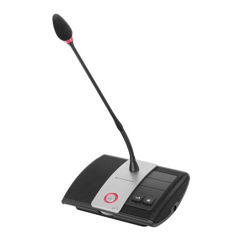
solutions for WIFI6301 Conference system mainframe, WIFI6302B Chairman Unit, WIFI6304B
delegate unit, and CR-WF30A wireless AP.
This manual is for user’s operation guidance only, not for maintenance. All changes in functions or
specifications after the publication of this manual will be illustrated separately. Please refer to
CREATOR or its distributors for the details.
This manual is protected by “Copyright Law of the People’s Republic of China” and other intellectual
property rights protection laws and regulations. This manual should not be copied or distributed
without written consent from CREATOR.

Menu
Chapter One, General Introduction.................................................................................................................... 0
1.1 About the Wired/Wireless Digital Network Integrated Conference System......................................0
1.2 System Features......................................................................................................................................0
1.3 System Equipment.................................................................................................................................. 1
1.4 System Diagram...................................................................................................................................... 1
Chapter Two, WI-FI Encrypted Conference System Mainframe....................................................................2
2.1 General Introduction.............................................................................................................................. 2
2.2 CR-WiFi6301 Front Panel..................................................................................................................... 2
2.3 CR-WiFi6301 Function Features .......................................................................................................... 4
2.4 CR-WiFi6301Front Panel Buttons Function........................................................................................ 5
2.4.1 Mainframe Menu Structure ......................................................................................................6
2.4.2 Button Function Illustration....................................................................................................... 7
2.4.3 Mainframe Menu Illustration......................................................................................................8
2.4.3.1 MIC MODE........................................................................................................................ 8
2.4.3.2 ACTIVE MIC ..................................................................................................................... 8
2.4.3.3 VOLUME ........................................................................................................................... 9
2.4.3.4 EQUALIZER.................................................................................................................... 10
2.4.3.5 ZONE................................................................................................................................ 11
2.4.3.6 UNIT SCAN ..................................................................................................................... 13
2.4.3.7 NETWORK SETTING.....................................................................................................13
2.4.3.8 TRANSLATE ................................................................................................................... 15
2.4.3.9 CAMERA......................................................................................................................... 16
2.4.3.10 LANGUAGE.................................................................................................................. 17
2.4.3.11 MISC............................................................................................................................... 17
2.4.3.12 DEFAULT............................................................................................................. …….18
2.4.3.13 VERSION....................................................................................................................... 19
2.4.4 Menu Software Illustration....................................................................................................... 19
2.4.4.1 MENU Options Illustration .............................................................................................. 19
2.4.4.1.1 “Connection” Options Illustration..................................................................... 20
2.4.4.1.2 “Conference System Mainframe” Options Illustration................................. 20
2.4.4.1.3 “UNIT MANAGEMENT” Options Illustration.................................................. 20
2.4.4.1.4 “WIFI MANAGEMENT” Options Illustration................................................... 21
2.4.4.1.5 “SOFTWARE LANGUAGE” Options Illustration ...........................................23
2.4.4.1.6 “EXIT” Options Illustration................................................................................ 23
2.4.4.2 Connection and Settings Reading.....................................................................................23
2.4.4.3 “MEETING MANAGEMENT” SETTINGS ................................................................... 23
2.4.4.3.1 Microphone mode.............................................................................................. 23
2.4.4.3.2 Speakers Quantity............................................................................................ 23
2.4.4.3.3 System Language ............................................................................................. 24
2.4.4.4 “AUDIO SETTINGS” CONFIGURATION..................................................................... 24
2.4.4.4.1 DSP AUDIO EFFECTS SETTINGS AND UNIT LOUDSPEAKER SWITCH
............................................................................................................................................... 24

2.4.4.4.2 Volume................................................................................................................ 24
2.4.4.4.3 SOUND FIELD CHOICE.................................................................................. 25
2.4.4.5 Camera Settings................................................................................................................. 25
2.4.4.5.1 CAMERAPROTOCOLS................................................................................... 25
2.4.4.5.2 CAMERA MAPPING.......................................................................................... 25
2.4.4.5.3 START CAMERA SETTINGS.......................................................................... 25
2.4.4.6 TRANSLATION SETTINGS........................................................................................... 26
2.4.4.6.1 Automatic Channel Selection........................................................................... 26
2.4.4.6.2 Total Translation Channel Quantity.................................................................26
2.4.4.6.3 Translation Room Settings............................................................................... 26
2.4.4.6.4 Channel Lock.....................................................................................................26
2.4.4.6.5 Channel Language............................................................................................ 26
2.4.4.7 Loudspeaker Zoning Settings ........................................................................................... 26
2.4.4.7.1 Loudspeaker Zoning......................................................................................... 27
2.4.4.7.2 Loudspeaker Zoing Settings............................................................................27
2.4.4.7.3 Loudspeaker Zoing Gain.................................................................................. 27
2.4.5 ID BUTTON .............................................................................................................................. 28
2.5 ETHERNET Cable Wiring Instructions............................................................................................. 28
2.6 CONTROLSYSTEM COM PIN Definition ...................................................................................... 28
2.7 AUDIO OUTPUTS 3.5mmAudio Interface Wiring Instruction....................................................... 29
2.8 CR-WiFi6301 Mainframe Installation................................................................................................ 29
2.9 CR-WiFi6301 Technical Specifications............................................................................................... 29
Chapter Three, Wifi Conference System Unit................................................................................................ 30
3.1 General Introduction............................................................................................................................ 30
3.2 CR-WiFi6302/4B Front Panel.............................................................................................................. 30
3.3 CR-WiFi6202/4B Function Features .................................................................................................. 31
3.4 CR-WiFi6302/4B Operation ................................................................................................................ 32
3.4.1 CR-WiFi6302/4B SSID and Password Settings.................................................................. 32
3.4.2 CR-WiFi6302/4B ID Settings.................................................................................................. 32
3.4.3 CR-WiFi6302/4BAudio DownloadAuthorization Settings................................................. 33
3.4.4 CR-WiFi6302/4B other commonly used interfaces............................................................. 33
3.4.5 CR-WiFi6202/4B Usage..........................................................................................................34
3.5 CR-WiFi6202/4BTechnical Specifications: ........................................................................................ 34
Chapter Four, Wireless AP............................................................................................................................... 35
4.1 General Introduction............................................................................................................................ 35
4.2 CR-WF30A Front Panel....................................................................................................................... 35
4.3 CR-WF30A Function Features ...........................................................................................................37
4.4 CR-WF30A Settings ............................................................................................................................. 37
4.4.1 Basic Settings........................................................................................................................... 38
4.4.2 Advanced Settings................................................................................................................... 39
4.4.2.1 Performance...................................................................................................................... 26
4.4.2.2 Dynamic Pool Settings ..................................................................................................... 40
4.4.3 Administration Settings............................................................................................................ 40
4.4.4 Take the Settings into Effect................................................................................................... 41

4.5 Connection Diagram............................................................................................................................. 41
4.6 Technical Specifications: ..................................................................................................................... 41
Chapter Five, System Settings......................................................................................................................... 42
5.1 System ID Settings................................................................................................................................ 42
5.1.1 Wireless AP Settings............................................................................................................... 42
5.1.2 System Connection.................................................................................................................. 42
5.1.3 Conference System Units Settings ....................................................................................... 43
5.2 Camera Auto-tracking Settings........................................................................................................... 42
5.2.1 Settings Steps.......................................................................................................................... 42
5.3 Settings for newly added Unit.............................................................................................................. 43
Chapter Six System Connection Diagram ...................................................................................................... 44
6.1 OneAP in One System Connection Diagram..................................................................................... 45
6.2 MultipleAPin One System Connection Diagram.............................................................................. 46
Chapter Seven Accessories.............................................................................................................................. 46
7.1 Charging Case.......................................................................................................................................46
7.2 CR-P2 Headphone............................................................................................................................... 47
7.3 CR-W6KL215B 215mm Cardioid Directional Microphone............................................................. 48
7.4 CR-M4KL415 knob 415mm Microphone (Optional) .......................................................................48
7.5 CR-DOCK10B Wireless Conference System Unit Charging Dock (Optional) .............................. 48
7.6 PowerAdapter ...................................................................................................................................... 48
7.7 RS-232 Communication Cable ............................................................................................................ 48
Chapter Eight Appendix.....................................................................................................................................48
8.1 CREATORConference System Protocols Format and Description................................................. 49
8.2 PELCO-D Camera Control Protocl Format and Illustration .......................................................... 49
8.3 PELCO-P Camera Control Protocl Format and Illustration .......................................................... 50
8.4 VISCACamera Control Protocl Format and Illustration ............................................................... 51
8.5 HD Camera CR-V1013 Settings.......................................................................................................... 52
8.5.1 CR-V1013 Camera Settings................................................................................................... 52
8.5.2 CR-V1013 Camera VISCAProtocol Connection ................................................................ 52
8.5.2.1 CR-V1013 RS-232 PIN definition.................................................................................... 52
8.5.2.2 CR-V1013 VISCAProtocols Connection......................................................................... 53
8.5.3 Conference System Mainframe, Matrix Switcher and the Camera’s Connection .......... 53

Chapter One, General Introduction
1.1 About the Wired/Wireless
Digital Network Integrated
Conference System
Wireless conference systems are extremely
convenient for installation and use, and not
limited by the meeting rooms, thus, thus, it has
become a very important direction of the
conference system technology development.
Oriented by the clients’ requirements, CREATOR
independently developed the wired/wireless
digital network integrated conference system.
The concise, intelligent design concept brings
convenience and flexibility to everything.
CREATOR WIRELESS/WIRED DIGITAL
NETWORK CONFERENCE SYSTEM includes
the mainframe, units, and the wireless AP, which
can satisfy different meeting requirements. Now,
no matter in small meeting rooms or in big
meeting halls, all kinds of meetings and seminars
can be conducted very conveniently and flexibly.
1.2 System Features
◆No need for wiring or drilling;
◆Saving Cost
WiFi Conference system does not need
redecoration, which is easy to use.
◆Not limited by the meeting rooms; swift
settings procedures; no damage caused to
the meeting room.
The wifi conference system is install-and-play.
No matter in what situation, the users can
immediately use the system after putting the
system on the table. And they can be also
immediately removed after the meeting.
◆No blocking, no interference
Standard 802.11n WIFI technology; strong
piercing capability; not interfered by the walking
people;
◆Internal Antenna
Internal antenna design, which keep a concise
outlook for the unit. What’s more, this design can
successfully protect the antenna to avoid the
interrupted communication due to damaged
antenna.
◆All-dimensional Status Indication
The conference system unit can display all status
information no matter the unit is online or offline.
◆Reliable Encryption System
Support WPA/WPA2 wireless security technology;
Support SSDI of 32bit length, SSID invisibility,
and 32 bit long key to ensure the privacy of the
meeting.
◆Mixed system of WIFI wireless conference
system and wired DIG system. It can completely
support CREATOR DIG Full-digital Conference
System; supporting voting, signing-in, digital
name plate, wired simultaneous interpretation, as
well as the wifi conference system.
◆DIG System supports looping connection
The DIG full-digital conference system supports
looping connection, which brings more stability.
◆Two-way DSP Processing
Two-way feedback and noise suppression. The
use can choose DSP processing for the
conference system unit or the 4 ways line output.
◆Perfect Sound Quality
Wireless non-compression audio transmission;
bandwidth: 20Hz ~ 20KHz; perfect sound quality.
◆Wireless Auto-tracking
Working with the CR-MVC4200HD and CR-

CREATOR COPORATION(CHINA) 2015-06 WWW.CREATOR.COM.CN
1
6301 Series Digital Wireless Conference SystemUser Manual
IRC20 to realize wireless unit IR localization
camera auto-tracking function.
◆4 ways loudspeaker zoning
Maximally support 4 ways loudspeaker zoning; 4
groups of zoned loudspeaker gain can be
adjusted separately.
◆Satisfying big scale meeting requirements
The Wifi conference system maximally supports
240 units, and the DIG Conference System
maximally supports 4000 units. When mixed and
used together, there can be maximally 4000 units
working under the same system.
◆Support PC Management Software
The wifi and DIG conference systems support
meeting software management.
1.3 System Equipment
CREATOR wireless/Wired integrated
digital network conference system mainly
include the following equipment:
◆CR-WiFi6301 Wireless digital network
conference system mainframe
◆CR-WiFi6302B Wireless digital network
conference system chairman unit
◆CR-WiFi6304B Wireless digital network
conference system delegate unit
◆CR-WF30A wireless access point
◆DIG Conference system unit and connection
box
1.4 System Diagram

CREATOR COPORATION(CHINA) 2015-06 WWW.CREATOR.COM.CN
2
6301 Series Digital Wireless Conference SystemUser Manual
Chapter Two, WI-FI Encrypted Conference
System Mainframe
2.1 General Introduction
The CR-WiFi6301 encrypted conference system
mainframe can control all the conference
functions altogether through the front panel
navigation buttons and the LCD display. There
are multiple meeting modes for selection:
speaker quantity selection, speaking mode
selection. It supports the mixed usage of the
WIFI conference system and the DIG full-digital
conference system. Two-way DSP technology
has been applied for the audio processing. The
built-in equalization module can ensure the high-
fidelity audio effect. It has also been integrated
with camera auto-tracking function to realize
whole course camera auto-tracking function for
the modern high technology meeting.
2.2 CR-WiFi6301 Front Panel
Front panel:
Back Panel:
①LCD Display
Display the menu settings page and
parameters for MIC MODE, MIC ACTIVE‘S,
BASS, TREBLE, VOLUME, CAMERA.
②MENU
Menu button, for menu options
③MODE
Microphone mode settings button; there are
following four modes:
◆FIFO: when the system reaches its
maximum allowed speakers quantity, the first
coming in speaker will be turned off by the latest

CREATOR COPORATION(CHINA) 2015-06 WWW.CREATOR.COM.CN
3
6301 Series Digital Wireless Conference SystemUser Manual
coming in speaker.
◆NORMAL: When the system reaches its
maximum allowed speakers quantity, the newly
applying speaker will automatically enter the
waiting queue.
◆FREE: maximally allow 6 speakers on at
the same time (not including the chairman unit);
new applying speaker will enter the waiting
queue automatically.
◆APPLY: the applying delegate units have
to be approved by the chairman unit; the waiting
speakers’ quantity is the same as the maximally
allowed speakers quantity; signing-in and voting
functions will close the delegate speakers or
clear the waiting queue.
④ACTIVE MICRO’S
Active speakers’ quantity limitation: when the
system is running on DIG mode, the
simultaneous active speakers’ quantity can be
1/2/4/6 pieces; when the system is running on
WIFI mode, the simultaneous active speakers
quantity can be 1/2/4 pieces.
⑤BASS
Low volume gain button for bass settings of the
microphone output audio
⑥TREBLE
High volume gain button for treble settings of the
microphone output audio
⑦VOLUME
Volume adjustment for line audio output; press
this button to enter line audio output volume
adjustment menu.
⑧AFC
Anti Feedback Control button; when the
mainframe menu chooses DSP channel 1, and
the indicator displays as DSP channel 1, this
button controls the channel 1 DSP status; the
same operation is for controlling channel 2.
When the indicator is ON, it means the AFC
function is ON; if there is no response after
pressing the button, it means there is no DSP
function.
⑨ANC
Anti Noise Control Button, when the mainframe
menu chooses DSP channel 1, and the indicator
displays as DSP channel 1, this button controls
the channel 1 DSP status; the same operation is
for controlling channel 2. When the indicator is
ON, it means the ANC function is ON; if there is
no response after pressing the button, it means
there is no DSP function.
⑩AGC
Automatic Gain Control Button, when the
mainframe menu chooses DSP channel 1, and
the indicator displays as DSP channel 1, this
button controls the channel 1 DSP status; the
same operation is for controlling channel 2.
When the indicator is ON, it means the AGC
function is ON; if there is no response after
pressing the button, it means there is no DSP
function.
11 and
Left and Right navigation button, for moving the
cursor left and right to make a selection.
12 ENTER
Confirm to execute operation button, used to
confirm the operations or save the settings.
13 ID
ID setting button, used for setting the system into
or out of ID Settings Status: long-press to enter
ID settings; Long-press again to exit ID Settings.
14 LINE IN

CREATOR COPORATION(CHINA) 2015-06 WWW.CREATOR.COM.CN
4
6301 Series Digital Wireless Conference SystemUser Manual
Line In 2 input can connect to remote video
conference and telephone conference terminal.
Through the operations on the menu: “Audio
Settings”–“Video Conference Volume”–“Line
In”, the Line In 2 input audio volume can be
adjusted. Select “Loudspeaker Zoning Settings”
“Video Conference Output”, the audio from
Line IN 2 will not be sent to the corresponding
Line out. When there is background music to
LINE IN 1, 3, 4, the mixed sound volume can be
adjusted through the menu software: “Audio
Settings” “Volume” “LINE IN”. The mixed
sound will keep output from the line out.
LINE IN1 and LINE IN 2 support both balanced
an d unbalanced input;
LINE IN 3: RCA interface, only supporting
unbalanced input;
LINE IN 4: only support balanced input;
15 AP
Audio download and authentication interface,
used for connection to CR-WF30A wireless AP’s
“AUDIO”jacket.
16 LINE OUT
Audio output interface, for connection to PA
system to amply the system audio, or to the
audio recording system.
When the loudspeaker zoning function is turned
off through the menu software, the output from
Line Out 1, 2, 3, 4 are the same.
When the loudspeaker zoning function is turned
on, the Line Out 1 is correspondent to the OUT 1
on the menu software; this correspondence is the
same between Line Out 2 and Out 2, Line Out 3
and Out 3, and Line Out 4 and Out 4.
The loudspeaker zones’ volume can be adjusted
through: “Audio Settings”–“Line Out”. When the
loudspeaker zoning function is turned on, the
gain of every zone can be adjusted separately.
17 DELEGATES——Conference System Unit
Connection Interface
Provides 2 ways DIG conference system unit
connection interfaces, which can connect to the
speaking unit, the translator console, or the unit
connection box. Loop connection is also
supported.
18 WiFi
The LAN (PoE) port for connection to CR-WF30A.
19 CONTROL SYSTEM
This port can connect to CREATOR intelligent
central controller, the camera auto-tracking
controller, or connection to the cameras directly
to realize camera auto-tracking function. When it
is directly connected to cameras that are using
RS485 protocol, there must be a RS232 to
RS485 converter in-between.
20 ETHERNET
1 way Ethernet connection interface for
connection to a computer to realize conference
system software management function.
21 AUX——RS-232 Serial Port
When the conference system mainframe directly
controls the cameras, this port can be connected
to CREATOR matrix switcher to realize multiple
cameras video input.
22 Grounding Pole
For grounding wiring
23 System Power input
Mainframe power supply input, supports
AC110V/220V
2.3 CR-WiFi6301 Function
Features
◆Support WPA/WPA2 wireless security
technology to ensure the privacy of the meetings
and avoid wiretapping and malicious interference.
Maximally support 32 bit SSID, 64-bit Key, and

CREATOR COPORATION(CHINA) 2015-06 WWW.CREATOR.COM.CN
5
6301 Series Digital Wireless Conference SystemUser Manual
SSID invisibility.
◆Support WIFI Conference system and DIG
Conference system at the same time;
◆DIG Full Digital Conference System supports
looping connection;
◆The provide 1 RJ45 interface can be used to
directly connect to one wireless AP or to a
network switch, then connect to multiple wireless
APs to suite the needs of large scale meeting.
Compatible with IEC 60914,GBT 15381-94;
Cat5e shielding cable; 100M network full
digital audio and control signals transmission to
ensure the sound quality over long distance
transmission;
Built-in with high performance CPU;
integrated with translation, discussion, voting,
signing-in, and digital name plate functions
together; Maximally support 4000 conference
system units;
Non-compression audio transmission; 48K
sample rate; 20Hz ~ 20KHz bandwidth; perfect
sound quality;
The system can support maximally 8 active
microphones at the same time, and for wireless
conference system, the max active microphone
quantity can be 6. Support 31+1 wired
simultaneous interpretation.
23 bit high speed DSP float point processing;
support 2 ways audio acoustic feedback
suppression and noise cancellation; provide clear
and high sensibility perfect audio quality;
Support PC management software, TCP/IP
control, providing reliable and safe management
and control;
Support PELCO-D, VISCA, SAMSUNG, and
CREATOR multiple camera control protocols;
working with CREATOR matrix switcher or
controller it can realize camera auto-tracking
function; together with HD camera auto-tracking
mainframe and HD IR auto-tracking camera, it
can realize WIFI conference system unit auto-
tracking function;
the PC management software can realize
centralized manage and smart malfunction
diagnosis of the units: it can analyze the model,
quantity, allocation, and malfunctions, etc.
Two-CCU hot backup function supported:
even though one of the two mainframes
malfunctions, the meetings can keep going on,
and the discussion, voting functions won’t be
disturbed;
Built with RCA, Phoenix, and XLR three
types interfaces for audio input; support balanced
and unbalanced connection for 4 ways mixed
audio input or 3 ways mix audio and 1 way
remote video conference input;
Built with RCA, Phoenix, and XLR three
types interfaces for audio output; support
balanced and unbalanced connection; Support
conference system units zoning, and adjusting
their sensibility; Support 4 ways loudspeakers
zoning output, which can effectively improve the
microphones’ gain without hawling effect; any
one of the output can be connected to remote
video conference system;
the LINE IN, remote video conference input,
4 ways audio output, conference system units’
volume can be adjusted independently; the
adjustable range is: -40dB ~ 0dB;
multiple types of microphone audio field are
provided; the users can also define their own
audio field effect;
the system can run without the PC
management software
the system codes can be maintained through
the network port;
2.4 CR-WiFi6301Front Panel
Buttons Function
For convenient management, operations, and

CREATOR COPORATION(CHINA) 2015-06 WWW.CREATOR.COM.CN
6
6301 Series Digital Wireless Conference SystemUser Manual
system settings CREATOR designed the
navigation panel and LCD display.
Basic Operation
Function Buttons -Navigation Buttons
ENTER confirm button Navigation buttons
ENTER to confirm
When the operations are complete, after about
10 seconds, if there is no any other operations,
the system will exit settings interface
automatically.
LCD Display
LCD will stay on after the mainframe is powered
up. It will display the current system status and
operations with white character color and a blue
background light.
Button Light
The button light will be flashing red color: when
the red light flash one time, it means this button’s
function or parameter is successfully selected,
and the LCD will also display the relevant
information.

CREATOR COPORATION(CHINA) 2015-06 WWW.CREATOR.COM.CN
7
6301 Series Digital Wireless Conference SystemUser Manual
2.4.2 Button Function Illustration
The operations under MENU button, you can
perform settings for MIC MODE, MIC ACTIVE‘S,
BASS, TREBLE, VOLUME, and CAMERA. The
detailed steps are as following:
1、Press down the “MENU” button, the LCD
display will show the first option “MIC MODE”;
2、Press ” ”or” ” to browse all the options,
and the same time, the LCD display will show the
current operation status. Choose the options you
want to change the settings of, and then press
“ENTER” to confirm.
3、After entering the option parameters settings
page, press ” ”or” ” to select the item you want
to change the settings of.
4、Press “ENTER” to confirm the set parameter.
If you have not exited the settings page,
when you press the “MENU” button, the LCD
will show the options of the last operation,
not the first option.
For example: The operations to set the
Microphone mode to NORMAL (set quantity
mode) are as following:
1, Press “MENU” button on the navigation panel
to enter the speakers’ mode selection page, at
the same time, its button light will be ON for one
time, and the LCD will display relevant
information.
2, Use the navigation buttons ” ” and ” ” to
move left and right. Every press of the button, the
button’s light will be turn on once. Select “MIC
MODE” and then press “ENTER” to enter the
microphone mode settings page. The “ENTER”
button light will be turned on, and the LCD
display will show the options for microphone
mode settings.
3、Press the navigation buttons ” ” and ” ” to
select the “NORMAL” mode, and its button light
will be turned on, and the LCD will display the
relevant message.
4、Finally, Press “ENTER” to confirm the

CREATOR COPORATION(CHINA) 2015-06 WWW.CREATOR.COM.CN
8
6301 Series Digital Wireless Conference SystemUser Manual
operations.
You can also directly press the “MODE” button on
the navigation panel to enter the menu settings.
And then only the step 3 and 4 of above will be
necessary to achieve the settings, which is faster
and more convenient.
2.4.3 Mainframe Menu Illustration
The mainframe menu mainly have 13 options:
MIC MODE
To set the microphone mode
ACTIVE MIC
To set the maximum active microphone quantity
VOLUME
To set the volume related parameters
EQUALIZER
Microphone equalizer settings, to set the
microphone sound field effects.
ZONE
To set the zones of the microphones
UNIT SCAN
To scan the conference system units
NETWORK SETTING
To set the network IP address, and the MAC
address
TRANSLATE
To set the translator console related parameters
CAMERA
To set the camera related parameters
LANGUAGE
To set the language of the conference system
units
MISC
Other mischievous settings
DEFAULT
Reset to factory settings
VERSION
Mainframe version number and manufacturer
information
After the mainframe is powered up, the
default page will show as following:
UNIT: it shows here the total conference system
units’ quantity. Units that have the same ID will
be recognized as one device. The devices that
don’t have a ID (e.g. the channel selector) will not
be counted in.
MIC: it shows here the microphone mode and
maximum active speakers quantity. In the above
image, it means the system is under “FIFO”
mode, and the maximum active microphone
quantity is 4.
2.4.3.1 MIC MODE
The following image shows the first level menu,
“MIC MODE” option, after pressing the “MENU”
button
Press “ENTER” button to enter, and you can set
the ”FIFO”,”NORMA”,”FREE”, and ”APPLY”
for the microphone mode.
2.4.3.2 ACTIVE MIC
The following image shows the second option
“ACTIVE MIC” of the first level menu.

CREATOR COPORATION(CHINA) 2015-06 WWW.CREATOR.COM.CN
9
6301 Series Digital Wireless Conference SystemUser Manual
Press “ENTER” button to enter, you can then set
the maximum active microphone quantity to be
1/2/4/6. Please note that while the mainframe’s
compatibility mode is set to be “WIFI”, the
maximum active microphone quantity can only be
1/2/4, and when it’s set to be “DIG”, the
maximum active microphone quantity can only be
1/2/4/6.
2.4.3.3 VOLUME
Here you can set all volume related parameters.
1)VOLUME –>LINE IN
Here you can set the LINE IN volume, shown as
the following image:
Under the “LINE IN” menu, press the “ENTER”
button to enter “LINE IN” volume settings. Then
you can press the navigation button to set the
volume level. The volume range can be; mute, -
40dB ~ 0dB.
2)VOLUME –>LINE OUT
Under the “LINE IN” menu, press the navigation
button to enter “LINE OUT” to set all line out
volume. The volume range can be; mute, -40dB
~ 0dB.
3)VOLUME –> UNIT
To set the conference system units’ earphone or
the original loudspeaker volume. The volume
range can be: mute, -40dB ~ 0dB.
4)VOLUME –> TREBLE
Microphone treble adjustment: the range is -12dB
~ 12dB.
5)VOLUME –> BASS
Microphone bass adjustment: the range is -12dB
~ 12dB.

CREATOR COPORATION(CHINA) 2015-06 WWW.CREATOR.COM.CN
10
6301 Series Digital Wireless Conference SystemUser Manual
6)VOLUME –> REMOTE IN
Remote video conference system interface
volume adjustment. The volume range can be:
mute, -40dB ~ 0dB.
7)VOLUME –> SPEAKER
Conference system units’ loudspeakers
adjustment, translator consoles’ loudspeakers not
included.
2.4.3.4 EQUALIZER
To set the equalizer for the microphones.
1)EQUALIZER-> SOUND EFFECT
”POPULAR”, ”SOFT”, ”STRENGTH”,”ROCK”, ”C
LASSIC”, ”OLD STYLE”, ”ORIGINAL”, ”CUSTOM”
are for the microphones’ sound effect. When the
“ORIGINAL” is selected, it means there is no equ
alizer, which will only take effect when selecting t
he following options: SOUND EFFECT->CUSTO
M, EQUALIZER->CUSTOM
2)EQUALIZER->CUSTOM:
You can set 7 equalizer bands parameters.
3)EQUALIZER->CUSTOM->100Hz settings:
4)EQUALIZER->CUSTOM->215Hz settings:
5)EQUALIZER->CUSTOM->400Hz settings:

CREATOR COPORATION(CHINA) 2015-06 WWW.CREATOR.COM.CN
11
6301 Series Digital Wireless Conference SystemUser Manual
6)EQUALIZER->CUSTOM->1KHz settings:
7)EQUALIZER->CUSTOM->2.2KHz settings:
8)EQUALIZER->CUSTOM->5KHz settings:
9)EQUALIZER->CUSTOM->11.5KHz settings:
2.4.3.5 ZONE
to set the speaker zones:
1)ZONE->OUT1 as shown in the following
image:
to set the loudspeakers’ zone one parameters.
2)ZONE->OUT1->ID RANGE
to se the ID range for the loudspeakers’ zone 1.
as shown in the following image:
3)ZONE->OUT1->ZONG1 GAIN
To set the gain value for zone 1 loudspeakers to
the mainframe OUT1. The range can be: mute, -
40dB ~ 0dB.
4)ZONE->OUT1->ZONG2 GAIN
To set the gain value for zone 2 loudspeakers to
the mainframe OUT1. The range can be: mute, -
40dB ~ 0dB.

CREATOR COPORATION(CHINA) 2015-06 WWW.CREATOR.COM.CN
12
6301 Series Digital Wireless Conference SystemUser Manual
5)ZONE->OUT1->ZONG3 GAIN
To set the gain value for zone 3 loudspeakers to
the mainframe OUT1. The range can be: mute, -
40dB ~ 0dB.
6)ZONE->OUT1->ZONG4 GAIN
To set the gain value for zone 4 loudspeakers to
the mainframe OUT1. The range can be: mute, -
40dB ~ 0dB.
7)ZONE->OUT2
8)ZONE->ZONE FUN
Loudspeakers zoning DSP processing, signal
ON/OFF.
9)ZONE->ZONE FUN->ZONE ENABLE
Zoning function switch: when set to be “ON”,
zoning function will be turned on, and the settings
of zoning for OUT1, OUT2, OUT3, and OUT4
take effect. When it’s set to be “OFF”, the zoning
function will be turned off, and the zoning settings
have no effect. The output OUT1, OUT2, OUT3,
and OUT4 of the mainframe are all the same.
10)ZONE->ZONE FUN->DSP 1
To set the signals processed by DSP1:
1: processing OUT1;
2: processing OUT2:
3: processing OUT3;
4: processing OUT4;
If the “UNIT ANC” is selected, then only “UNIT”
can be processed, and only 1 channel can be
selected for processing.
11)ZONE->ZONE FUN->DSP 2
To set the signals processed by DSP2:
1: processing OUT1;
2: processing OUT2:
3: processing OUT3;
4: processing OUT4;
If the “UNIT ANC” is selected, then only “UNIT”
can be processed, and only 1 channel can be
selected for processing.
Table of contents
Other Creator Conference System manuals
