crest Optics X-Light V2 TP User manual

1
CREST OPTICS
X-Light™V2TP
Confocal Imager
VCS
Super-resolution module
Installation and
User’s Guide
V1.9

2
CREST OPTICS SRL
via Mattia Battistini, 184D 00167 Roma www.crestopt.com
Tel. +39 066147496 FAX +39 0661662738 E-mail: info@crestopt.com

3
CREST OPTICS X-Light V2TP –Installation and user guide
1.0 X-Light V2TP hardware
1.1 X-Light V2TP Description
1.2 X-Light V2TP Specifications
1.3 X-Light V2TP Light path
2.0 X-Light V2TP Installation
2.1 X-Light V2TP Components
2.2 Filter Wheels Assembly
2.2.1 Filter descriptions for most common applications (filters are not included)
2.2.2 Changing emission filters and dichroic mirrors
2.3 Power Supply for X-Light V2TP and Connectors
2.3.1 Cleaning on X-Light V2TP System
2.3.2 Wheels positioning for filters extraction
2.3.3 Laser safety interlock
2.4 Attaching X-Light V2TP to the Microscope
2.5 Spinning disk box Plug IN/Plug OUT
2.6 Attaching the Camera
2.7 X-Light V2TP Alignment
2.8 Maintenance
2.9 Installing X-Light V2TP Drivers
3.0 X-Light V2TP Options
3.1 VCS –Video Confocal Super-resolution
3.1.1 Crest VCS description
3.1.2 VCS connectors
3.1.3 Alignment procedure
3.1.4 VCS Mask Replacement
4.0 X-Light V2TP Command Sets

4
1.0 X-Light V2TP hardware
1.1 X-Light V2TP description
CREST X-Light V2TP is a high throughput full spectrum spinning disk confocal imager with super-resolution
add-on module capability. It can be attached to all major inverted epi-fluorescence microscopes allowing full
spectrum (360nm-700 nm) confocal imaging.
Detailed Specification:
•Easy plug-in spinning disk box
•Full compatibility with Crest VCS (Video Confocal Super-resolution) module for 3D resolution enhancement
•Microscope side-port adapter mounting for original C-mount adapter
•Single hole pattern spinning disk or double hole pattern spinning disk, on same physical disk
- High density hole patterns, with Nipkow design
•Anti Reflection coated spinning disk for highest throughput on the market
•Fast spinning disk 15.000 rpm
•Up to 2000 frame/s (tested with CMOS High Speed Systems)
• Custom hole patterns are available for dedicated applications (90-120 days delivery), from receipt of
customer specification/pattern geometrical description
•Excitation Gimbal mount for easy alignment on custom microscope setup and for best S/N
•LED and Laser excitation mounts for high efficiency coupling
•Motorized Dichroic five positions Filter Wheel
•Standard eight positions motorized Emission Wheel
•Extraction tools for easy insertion and removal of both dichroic filter and emission filter
•Up to 22mm field of view for new sCMOS confocal imaging on single hole pattern disk
•Up to 12mm x 12mm field of view in double pattern configuration (for each pattern)
•CCD focal plane easy focusing without moving the CCD Camera
•Adapter for Multimode Laser or SMA-905 fiber excitation
5
CREST X-Light V2TP can be used with most high end EMCCDs, interline or frame transfer CCD cameras,
sCMOS cameras together with imaging software including Metamorph, Nis Element and MicroManager.
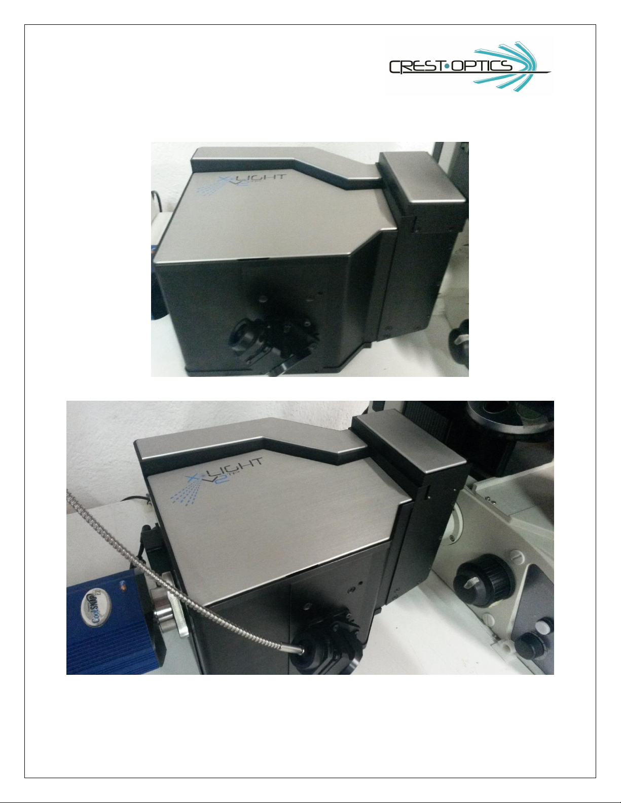
Fig. 1.1 CREST X-Light V2TP
Fig 1.2 CREST X-Light V2TP complete system.

6
1.2 CREST X-Light V2TP Confocal Imager
Specifications
Confocal scanner
Nipkow spinning Disk (pinholes) with single
and double hole pattern
Disk scan rate
> 2000 scans per second
Pinhole diameter
60 micron single pattern standard, 40-70
micron double pattern standard, custom pattern
on request
Spectral transmission
360 nm –700 nm
Z- resolution
0.7 micron (PSF); 60X PlanApo 1.4NA
Illumination source
Lumencor LEDs Systems, Laser illumination
System
Internal excitation changer
On request
Internal dichroic changer
Automated 5 position wheel (up to 25.5x36 mm
filters).
Internal emission changer
Automated 8 positions wheel (25mm diameter,
up to 5mm thick filter).
Operation mode
Automated confocal, wide field, bright field,
super-resolution with VCS module add-on
(option)
Observation
CCD camera/sCMOS camera port with fixed
position; manual focusing by X-Light V2TP
focusing hex screw system
Microscope Compatibility
Inverted fluorescence microscopes with 100%
camera port. Upright Microscopes
Control
USB serial control
Software
Metamorph, Nis-Elements, MicroManager
Size
11.4 (w)x 14.2 (L) x 9.06 (h) inches
29.00 (w) x 36.00 (L) x 23.00 (h) cm
Sound noise
Background 37db working 45db
Working Temperature
15-35 °C
Storage Temperature
10-70°C
Weight
24.3 lbs /11.0Kg
Power
100-240VAC 2.5A 47-63Hz
graphic symbols:
Not dispersion this product in the environment in accordance to RAEE directive 2003/118CE
Attention
7
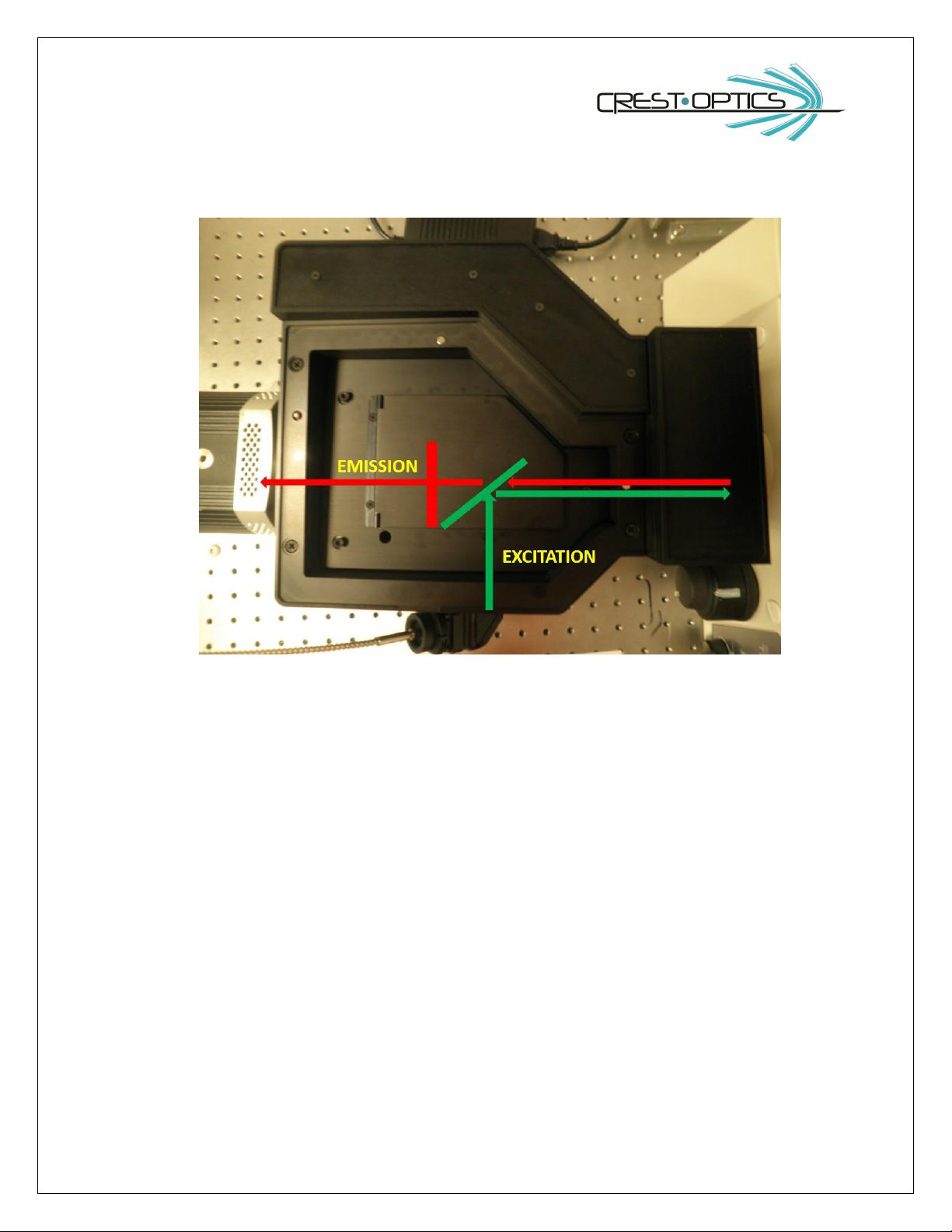
1.3 CREST X-LIGHT V2 Light Path
X-LIGHT V2TP Confocal Imager Light path
Excitation Filter Wheel: The X-Light V2TP has been engineered to work with LEDs and Lasers mainly.
Dichroic Filter Wheel: The quick release dichroic wheel has 5, positions and accepts commercially
available up to 25.5x36 mm dichroic mirrors. Dichroic positions can be controlled via serial commands
(software control).
Emission Filter Wheel: The quick release emission filter wheel has 8 filters positions and accepts
commercially available 25mm filters (up to 5mm thickness ring mounting included).
Dichroic positions can be controlled via serial commands (software control).
Spinning Disk: The Nipkow spinning disk can be moved in and out of the light path and confocal images
and wide-field images can be obtained respectively. The spinning disk can be controlled via serial
commands (software control).
Camera: A wide range of CCD/EMCCD cameras and sCMOS cameras can be attached to the confocal unit
to obtain confocal, wide field or bright field images.

8
2.0 CREST X-LIGHT V2TP Installation
2.1 CREST X-LIGHT V2TP Components
1
Confocal Head
2
Automated dichroic wheel filter holders (5)
3
Camera C-Mount
4
X-Light power supply
5
Power cord
6
USB cable
8.1
Dichroic Filter extraction tool for automated 5 positions
dichroic wheel

9
8.2
Emission Filter extraction tool for automated 8 positions filter
wheel
9
Bubble level
10
C-mount side-port adapter ring
11
Threaded ring (2)

10
2.2 Filter wheels Assembly
2.2.1 Filter descriptions for most common applications (filters are not included)
DAPI Chroma technology®
Exciter
Dichroic
Emission
11
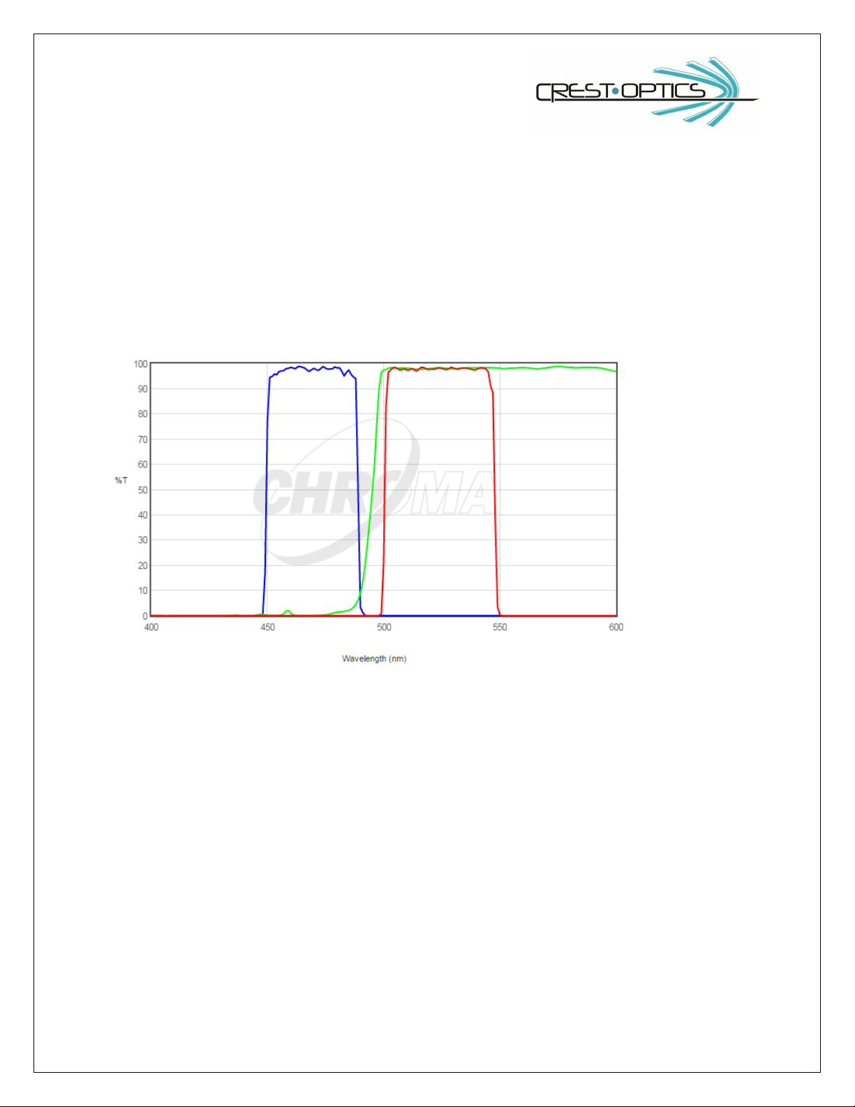
EGFP Chroma Technology®
Exciter
Dichroic
Emission
12
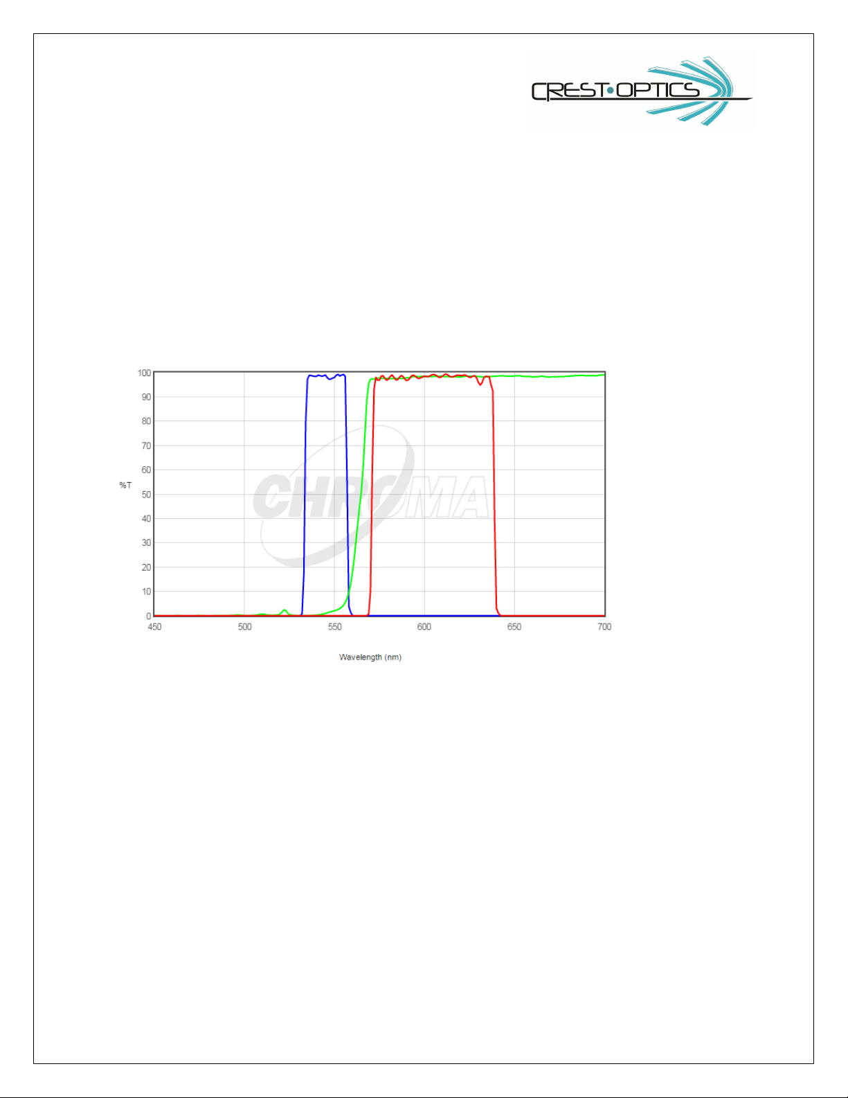
TRITC/Cy3 Chroma Technology®
Exciter
Dichroic
Emission

13
2.2.2 Changing emission filters and dichroic mirrors
Changing emission filters:
In order to change or add new emission filter sets follow the procedure below. Please refer to section 2.3.2
for both dichroic wheel and emission wheel positioning for filter exchange.
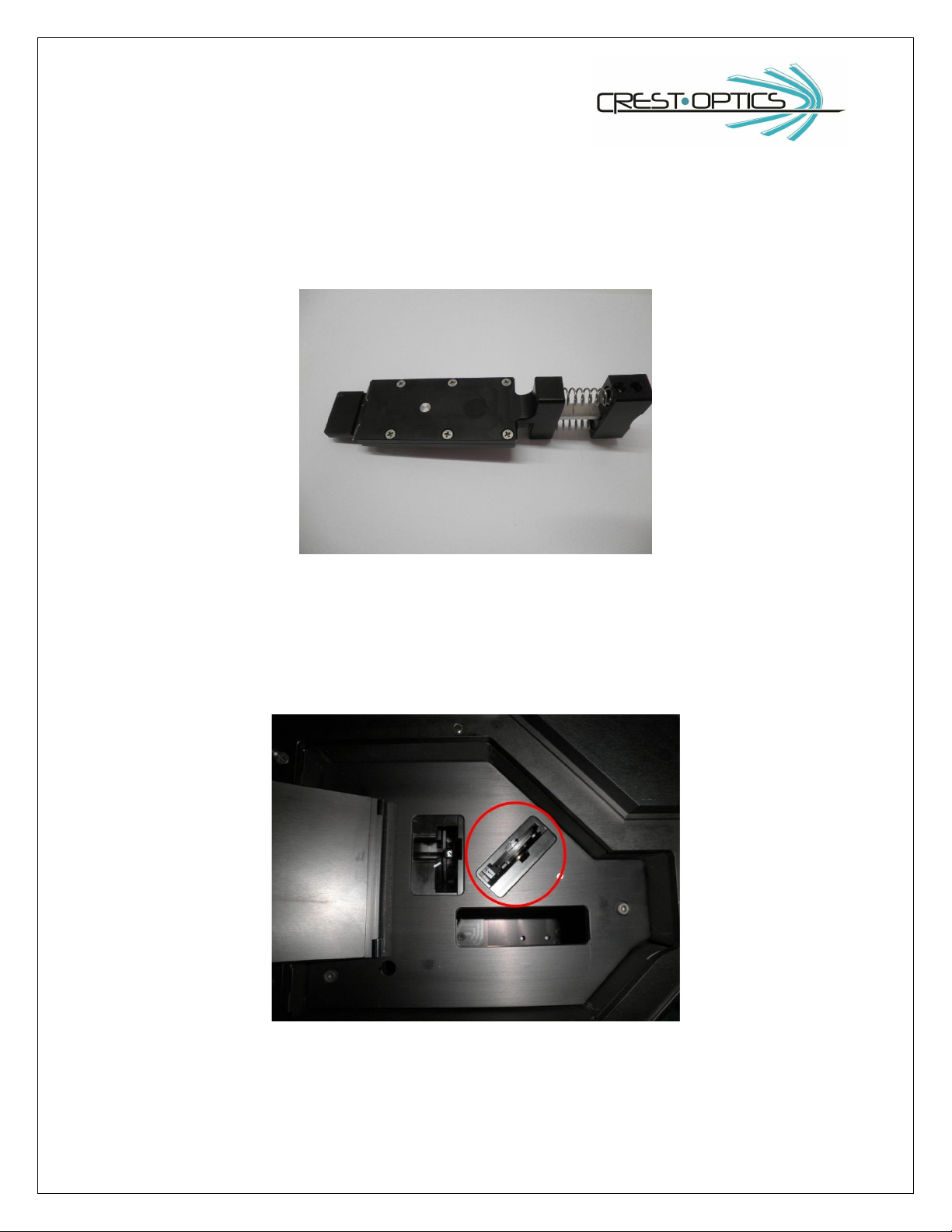
Figure: Emission Extraction tool
Insert the filter:
1. Locate the emission slot circled in the figure below

14
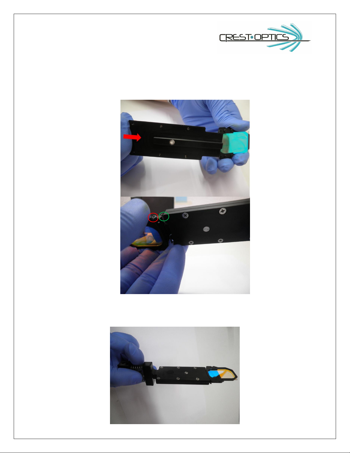
2. Push the emission tool and keeping it pushed place the emission filter in it as shown in figure below
(every manufacturer has its proper way to place the filter in the optical path so follow manufacturer
instructions in order to mount them correctly.)
3. Release the tool in order to grab the filter in steady position

15
4. Insert the tool all the way down in the slot following the slot entry shape
5. Now start extracting: press the tool and move it in the direction of the red arrow below

16
6. Finally pull out the tool
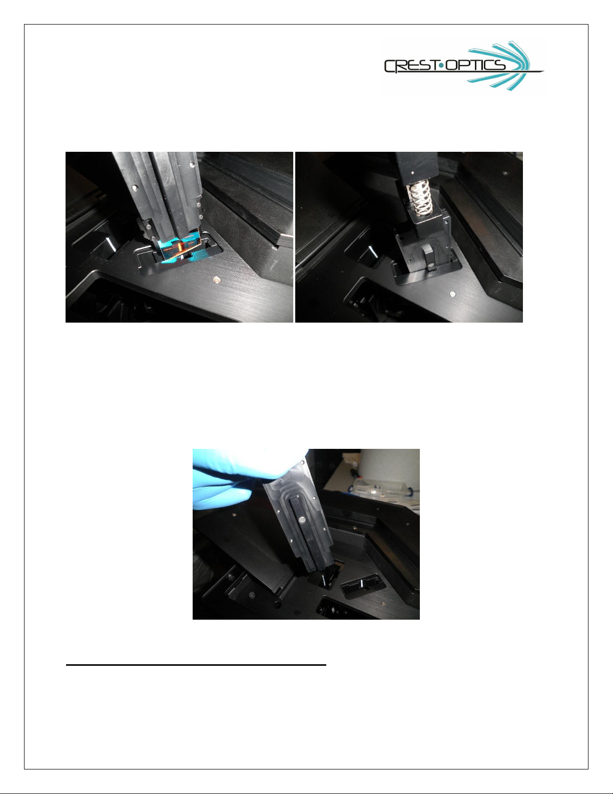
Extract the filter (inverse insertion procedure):
1. Push the top of the extraction tool.
2. Insert the extraction tool in the filter slot of emission wheel. Make sure the extraction tool is
completely inserted against the wall indicated by the red arrow (see picture above)
3. Once in position push a little the toll toward the filter and release in order to grab the filter and
extract it.

17
Changing dichroic filters:
Extra precaution is necessary when mounting or removing dichroic filters. Lay the dichroic filter holder flat on
a flat surface so that the mounting screws are facing upwards (see figure)
Using a Phillips screw driver unscrew the filter holding plate . Now gently remove the holding plate.
It is important how the dichroic mirror is mounted on the holder. The coated surface of the mirror should be
facing away from you as it sits on the flat surface. In other words the coated surface should face the light
source. The coated surface has the beveled edge or on occasion the manufacturer would specify using an
arrow marked at the edge.
Once the mirror is placed in the filter wheel, carefully place the holding plate in position and gently tighten
the screws. Make sure not to tighten it too much since this may cause the mirror to fracture. A good way to
keep check is to gently shake the filter wheels after a few turns on the screw, if you here a rattle you can
tighten a bit more. Follow this until the rattle stops.
The filter are now ready for mounting on the confocal head.
18
Figure: Dichroic Extraction tool
Insert the filter:
1. Locate the dichroic slot circled in the figure below
19
2. Push on the top of the dichroic tool and keeping it pushed place the dichroic mirror in it as shown in
figure below (pay attention to mount it with the coated surface toward the excitation light).
3. Release the tool in order to grab the filter in steady position. The two metal hooks (green circle above)
must grab the two corresponding hooks on dichroic holder (red circle above)
20
4. Insert the tool all the way down in the slot following the slot entry shape
5. Finally, push on the top of the tool again and extract it. The dichroic is correctly positioned into the
wheel.
In order to extract a filter follow the inverse procedure:
Insert the tool with the button on top pressed, once in position all the way down release the button and extract
the filter
Table of contents
Popular Laboratory Equipment manuals by other brands


Unitech
Unitech MS339 quick guide

Thermo Scientific
Thermo Scientific 3050 user manual

Agilent Technologies
Agilent Technologies 1141A User's and service guide

Tuttnauer
Tuttnauer Valueklave 2540 Operation & maintenance manual

Hach
Hach TitraLab AT1000 Series Basic user manual

SKC
SKC 225-68 operating instructions