CRL LD195 User manual

© COPYRIGHT C.R. LAURENCE CO., INC. 2013
Sub ect to printing errors and design changes over which we have no control. In the event of problems please contact our Customer Service Department.
AVDB3104 05.13
AC.R. LAURENCE Co., INC.
Reciprocating Saw
CAT. NO. LD195, LD195EU, LD195AU
+&"" +52; B@6;4 2920A?60 A<<9@ :.056;2@ <? 2>B6=:2;A /.@60 @.32AF
=?20.BA6<;@ @5<B91 .9D.F@ /2 3<99<D21 A< ?21B02 A52 ?6@8 <3 36?2 2920A?60 @5<08
.;1=2?@<;.96;7B?F<:=92A29F?2.1A52:.;B.9/23<?2=?<02216;4A<B@2A56@A<<9
Visit us at for international toll free information

+&"" Read all safety warnings and instructions. Failure to follow the
warnings and instructions may result in electric shock, fire and/or serious injury.
Save all warnings and instructions for future reference.
The term "power tool" in the warnings refers to your electric (corded) power tool.
A
This is the safety alert symbol.
It is used to alert you to potential
personal injury hazards. Obey all
safety messages that follow this
symbol to avoid possible injury
or death.
"& Indicates a hazardous
situation which, if not avoided,
will result in death or
serious injury.
;A56@:.;B.9<;A529./296;4.;1.99<A52?6;3<?:.A6<;=?<C6121
D6A5A56@=?<1B0A
+&"" Indicates a hazardous
situation which, if not avoided,
could result in death or
serious injury.
)(#", used with the safety
alert symbol, indicates a
hazardous situation which,
if not avoided, could result in
minor or moderate injury.
"#( is used to address
practices not related to
personal injury.
)(#", without the safety
alert symbol, is used to address
practices not related to
personal injury.
22=+<?8?2.+299 6A
Cluttered or dark areas invite accidents.
<;<A<=2?.A2=<D2?A<<9@6;2E=9<@6C2.A:<@=52?2@@B05.@6;A52=?2@2;02<339.::./92
96>B61@4.@2@<?1B@A
Power tools create sparks which may ignite the dust or fumes.
22=05691?2;.;1/F@A.;12?@.D.FD5692<=2?.A6;4.=<D2?A<<9
Distractions can cause you to lose control.
"& $#+&(## '(-+&""'
Visit us at for international toll free information 1
!$#&("('(-"#&!(#"

A
Visit us at for international toll free information 2
$<D2?A<<9=9B4@:B@A:.A05A52<BA92A"2C2?:<163FA52=9B46;.;FD.F
<;<AB@2.;F.1.=A2?=9B4@D6A54?<B;121=<D2?A<<9@
Unmodified plugs and matching outlets will reduce risk of electric shock.
C<61/<1F0<;A.0AD6A54?<B;121@B?3.02@@B05.@=6=2@?.16.A<?@?.;42@.;1?23?642?.A<?@
There is an increased risk of electric shock if your body is grounded.
<;<A2E=<@2=<D2?A<<9@A<?.6;<?D2A0<;16A6<;@
Water entering a power tool will increase the risk of electric shock.
<;<A./B@2A520<?1"2C2?B@2A520<?13<?0.??F6;4=B996;4<?B;=9B446;4A52=<D2?A<<9
22=0<?1.D.F3?<:52.A<69@5.?=2142@<?:<C6;4=.?A@
Damaged or entangled cords increase the risk of electric shock.
+52;<=2?.A6;4.=<D2?A<<9<BA1<<?@B@2.;2EA2;@6<;0<?1@B6A./923<?<BA1<<?B@2
Use of a cord suitable for outdoor use reduces risk of electric shock.
3<=2?.A6;4.=<D2?A<<96;.1.:=9<0.A6<;6@B;.C<61./92
B@2.?<B;1.B9A6?0B6A;A2??B=A2?=?<A20A21@B==9F
Use of a GFCI reduces the risk of electric shock.
(& '(-
'A.F.92?AD.A05D5.AF<B.?21<6;4.;1B@20<::<;@2;@2D52;<=2?.A6;4.=<D2?A<<9
<;<AB@2.=<D2?A<<9D5692F<B.?2A6?21<?B;12?A526;39B2;02<31?B4@.90<5<9<?:2160.A6<;
A moment of inattention while operating power tools may result in serious personal injury.
)@2=2?@<;.9=?<A20A6C22>B6=:2;A9D.F@D2.?2F2=?<A20A6<;
Safety equipment such as dust masks, non-skid safety shoes, hard hats, or hearing protection used for
appropriate conditions will reduce personal injuries.
$?2C2;AB;6;A2;A6<;.9@A.?A6;42@B?2A52@D6A056@6;A52<33=<@6A6<;/23<?2
0<;;20A6;4A<=<D2?@<B?02=6086;4B=<?0.??F6;4A52A<<9
Carrying power tools with your finger on the switch or energizing power tools that have
the switch on invites accidents.
<;<A<C2??2.0522==?<=2?3<<A6;4.;1/.9.;02.A.99A6:2@
This enables better control of the power tool in unexpected situations.
?2@@=?<=2?9F<;<AD2.?9<<@209<A56;4<?72D29?F22=F<B?5.6?09<A56;4.;1
49<C2@.D.F3?<::<C6;4=.?A@
oose clothes, jewelry or long hair can be caught in moving parts.
312C602@.?2=?<C61213<?A520<;;20A6<;<31B@A2EA?.0A6<;.;10<9920A6<;3.0696A62@
2;@B?2A52@2.?20<;;20A21.;1=?<=2?9FB@21
Use of these devices can reduce dust-related hazards.
#;9FB@2@.32AF2>B6=:2;AA5.A5.@/22;.==?<C21/F.;.==?<=?6.A2@A.;1.?1@.42;0F
Unapproved safety equipment may not provide adequate protection. Eye protection must be ANSI-approved
and breathing protection must be NIOSH-approved for the specific hazards in the work area.
$&'#" '(-

A
Visit us at for international toll free information 3
<;<A3<?02A52=<D2?A<<9)@2A520<??20A=<D2?A<<92>B6=:2;A
The correct power tool will do the job better and safer at the rate for which it was designed.
<;<AB@2A52=<D2?A<<963A52@D6A051<2@;<AAB?;<;<?<33
Any power tool that cannot be controlled with the switch is dangerous and must be repaired.
6@0<;;20AA52=9B43?<:A52=<D2?@<B?02/23<?2:.86;4.;F.17B@A:2;A@
05.;46;4.002@@<?62@<?@A<?6;4=<D2?A<<9@
Such preventive safety measures reduce the risk of starting the power tool accidentally.
'A<?26192=<D2?A<<9@<BA<3A52?2.05<305691?2;.;11<;<A.99<D=2?@<;@
B;3.:696.?D6A5A52=<D2?A<<9<?A52@26;@A?B0A6<;@A<<=2?.A2A52=<D2?A<<9
Power tools are dangerous in the hands of untrained users.
!.6;A.6;=<D2?A<<9@52083<?:[email protected];:2;A<?/6;16;4<3:<C6;4=.?A@/?2.8.42<3=.?A@.;1
.;F<A52?0<;16A6<;A5.A:.F.3320AA52=<D2?A<<9@<=2?.A6<;31.:.4215.C2A52=<D2?A<<9
?2=.6?21/23<?2B@2
Many accidents are caused by poorly maintained power tools.
22=0BAA6;4A<<9@@5.?=.;1092.;
Properly maintained cutting tools with sharp cutting edges are less likely to bind and easier to control.
)@2A52=<D2?A<<9.002@@<?62@.;1A<<9/6A@2A06;.00<?1.;02D6A5A52@26;@A?B0A6<;@A.86;4
6;A<.00<B;AA52D<?86;40<;16A6<;@.;1A52D<?8A</2=2?3<?:21
Use of the power tool for operations different from those intended could result in a hazardous situation.
$#+&(## )'"&
Have your power tool serviced by a qualified repair person using only identical replacement parts.
This will ensure that the safety of the power tool is maintained.
'&*
<91=<D2?A<<9/F6;@B9.A214?6==6;4@B?3.02@D52;=2?3<?:6;4.;<=2?.A6<;D52?20BAA6;4A<<9
:.F0<;A.0A56112;D6?6;4<?6A@<D;0<?1
Contact with a "live" wire will make exposed metal parts of the tool "live" and shock the operator.
)@209.:=@<?.;<A52?=?.0A60.9D.FA<@20B?2.;1@B==<?AA52D<?8=6202A<.@A./92=9.A3<?:
Holding the work by hand or against your body leaves it unstable and may lead to loss of control.
!.6;A.6;9./29@.;1;.:2=9.A2@<;A52A<<9
These carry important safety information. If unreadable or missing, contact CR customer service
for a replacement.
C<61B;6;A2;A6<;.9@A.?A6;4
Prepare to begin work before turning on the tool.
<;<A9.FA52A<<91<D;B;A696A5.@0<:2A<.0<:=92A2@A<=
Moving parts can grab the surface and pull the tool out of your control.
&$&#("'+'(-+&""'

A
Visit us at for international toll free information 4
+52;B@6;4.5.;15291=<D2?A<<9:.6;A.6;.36?:4?6=<;A52A<<9D6A5/<A55.;1@A<
?2@6@A@A.?A6;4A<?>B2
<;<A92.C2A52A<<9B;.AA2;121D52;6A6@=9B44216;A<.;2920A?60.9<BA92AG
Turn off the tool, and unplug it from its electrical outlet before leaving.
(56@=?<1B0A6@;<A.A<F Keep it out of reach of children.
$2<=92D6A5=.02:.82?@@5<B910<;@B9AA526?=5F@606.;@/23<?2B@2
Electromagnetic fields in close proximity to a heart pacemaker could cause pacemaker
interference failure. In addition, people with pacemakers should:
• Avoid operating alone.
• Do not use with power switch locked on.
• Properly maintain and inspect to avoid electrical shock.
• Properly ground power cord. Ground Fault Circuit Interrupter (GFCI) should also be implemented
- it prevents sustained electrical shock.
10. +&"" Some dust created by power sanding, sawing, grinding, drilling, and other construction
activities contains chemicals known [to the Sate of California] to cause cancer, birth defects or other
reproductive harm. Some examples of these chemicals are:
• ead from lead-based paints.
• Crystalline silica from bricks and cement or other masonry products.
• Arsenic and chromium from chemically treated lumber.
Your risk from these exposures varies, depending on how often you do this type of work. To reduce your
exposure to these chemicals: work in a well ventilated area, and work with approved safety equipment,
such as dust masks that are specially designed to filter out microscopic particles.
11. +&"" Handling the cord on this product will expose you to lead, a chemical known to the State of
California to cause cancer and birth defects or other reproductive harm. Wash hands after handling.
12. The warnings, precautions, and instructions discussed in this instruction manual cannot cover all possible
conditions and situations that may occur. It must be understood by the operator that common sense and
caution are factors which cannot be built into this product, but must be supplied by the operator.
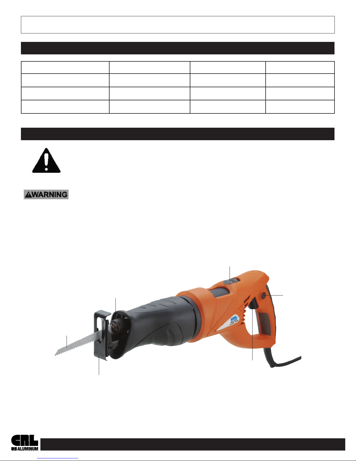
This tool vibrates during use. Repeated or long-term exposure to vibration may cause temporary or permanent
physical injury, particularly to the hands, arms and shoulders. To reduce risk of vibration-related injury:
1. Anyone using vibrating tools regularly for an extended period should first be examined by a doctor
and then have regular medical check-ups to ensure medical problems are not being caused or worsened
from use. Pregnant women or people who have impaired blood circulation to the hand, past hand injuries,
nervous system disorders, diabetes, or Raynaud's Disease should not use this tool. If you feel any
symptoms related to vibration (such as tingling, numbness, and white or blue fingers), seek medical advice
as soon as possible.
2. Do not smoke during use. Nicotine reduces the blood supply to the hands and fingers,
increasing the risk of vibration-related injury.
3. Wear suitable gloves to reduce the vibration effects on the user.
4. Use tools with the lowest vibration when there is a choice.
*&(#"'(-

A
1. Tools marked with "Grounding Requirement" have a three wire cord
and three prong grounding plug. The plug must be connected to a
properly grounded outlet. If the tool should electrically malfunction or
break down, grounding provides a low resistance path to carry
electricity away from the user, reducing the risk of electric shock.
(See 3-Prong Plug and Outlet).
2. The grounding prong in the plug is connected through the green wire
inside the cord to the grounding system in the tool. The green wire in
the cord must be the only wire connected to the tool's grounding
system and must never be attracted to an electrically "live" terminal.
(See 3-Prong Plug and Outlet).
3. The tool must be plugged into an appropriate outlet, properly installed
and grounded in accordance with all codes and ordinances. The plug
and outlet should look like those in the preceding illustration.
(See 3-Prong Plug and Outlet).
1. Tools marked "Double Insulated" do not require grounding.
They have a special double insulation system which satisfies
OSHA requirements and complies with the applicable standards of
Underwriters aboratories, Inc., the Canadian Standards Association,
and the National Electrical Code.
2. Double insulated tools may be used in either of the 120 volt outlets
shown in the illustration to the left (See Outlets for 2-Prong Plug).
Check with a qualified electrician if you are in doubt as to whether the outlet is properly grounded.
Do not modify the power cord plug provided with the tool. Never remove the grounding prong from the plug.
Do not use the tool if the power cord or plug is damaged. If damaged, have it repaired by a service facility
before use. If the plug will not fit the outlet, have a proper outlet installed by a qualified electrician.
(#$&*"( (&'#"(&#!"#&&(&#)""
+&#""(#"
DOUBLE INSULATED TOOLS: TOOLS WITH TWO PRONG PLUGS
#BA92A@3<?$?<;4$9B4
$?<;4$9B4.;1#BA92A
Visit us at for international toll free information 5
5. Include vibration-free periods each day of work.
6. Grip tool as lightly as possible (while still keeping safe control of it). et the tool do the work.
7. To reduce vibration, maintain the tool as explained in this manual. If any abnormal vibration occurs,
stop use immediately.
&#)""

A
1. Grounded tools require a three wire extension cord. Double insulated tools can use either a two or three
wire extension cord.
2. As the distance from the supply outlet increases, you must use a heavier gauge extension cord.
Using extension cords with inadequately sized wire cause a serious drop in voltage, resulting in loss of
power and possible tool damage. (See Table A below.)
3. The smaller the gauge number of the wire, the greater the capacity of the cord. For example,
a 14 gauge cord can carry a higher current than a 16 gauge cord. (See Table A below.)
4. When using more than one extension cord to make up the total length, make sure each cord
contains at least the minimum wire size required. (See Table A below.)
5. If you are using one extension cord for more than one tool, add the nameplate amperes and use
the sum to determine the required minimum cord size. (See Table A below.)
6. If you are using an extension cord outdoors, make sure it is marked with the suffix "W-A"
("W" in Canada) to indicate it is acceptable for outdoor use.
7. Make sure the extension cord is properly wired and in good electrical condition.
Always replace a damaged extension cord or have it repaired by a qualified electrician before using it.
8. Protect the extension cords from sharp objects, excessive heat, and damp or wet areas.
(./92&20<::2;121!6;6:B:+6?2.B423<?
EA2;@6<;<?1@*<9A
".:2=9.A2:=2?2@
.A3B999<.1
EA2;@6<;<?1 2;4A5
5.1 - 7.0 18 16 14 12 12
7.1 - 12.0 18 14 12 10 -
12.1 - 16.0 14 12 10 - -
16.1 - 20.0 12 10 - - -
* Based on limiting the line voltage drop to five volts
at 150% of the rated amperes.
Double Insulated
Canadian Standards Association
Underwriters aboratories, Inc.
Volts Alternating Current
Amperes
+&"" marking concerning
risk of eye injury. Wear
ANSI-approved safety goggles
with side shields.
Read the manual before set-up
and/or use
+&"" marking concerning
risk of electric shock. Properly
connect the power cord to
appropriate outlet.
SYMBOLOGY
Visit us at for international toll free information 6
,("'#"#&'

A
("# ) )
Electrical Rating 120V / 60 HZ / 6 A 220V / 50 HZ / 800W 240V / 50 HZ / 800W
Speed 0-2500 SPM 0-2500 SPM 0-2500 SPM
Stroke ength 7/8" 22.2 mm 22.2 mm
Read the "(&!$#&("('(-"#&!(#" section at the beginning
of this manual including all text under subheadings therein before set up or use of
this product.
(#$&*"('&#)'")&-&#!"( #$&(#" Turn the
power switch of the tool off and unplug the tool from its electrical outlet before
assembling or making any adjustments to the tool.
"#( For additional information regarding the parts listed in the following pages, refer to Parts ist and
Assembly Diagram on pages 12 and 13.
Visit us at for international toll free information 7
'$(#"'
'()$#&)'
Saw Blade
Chuck
Rotation Switch
Pivoting Shoe
Trigger
Trigger
ock
Button

A
Visit us at for international toll free information 8
#$&(""'(&)(#"'
Read the "(&!$#&("('(-"#&!(#" section at the beginning
of this manual including all text under subheadings therein before set up or use of
this product.
(#$&*"('&#)'")&-&#!"( #$&(#" Squeeze the
release Trigger and unplug the tool from its electrical outlet before performing any
procedure in this section.
INSTALLING THE SAW BLADE
1. If there is an installed blade, remove it by opening
the Chuck and pulling the blade out. To open the
Chuck, rotate it counterclockwise and hold it in the
open position.
2. Release the Chuck to close it.
3. To install the new Saw Blade, rotate and hold the
Chuck counterclockwise while inserting the Saw
Blade and pushing it in to its deepest position.
4. Release the Chuck to close it.
5. Check that the Saw Blade is firmly locked in place
and that the teeth are pointed downward.
+&"" To prevent serious injury: Before plugging
in the Power Cord for each use, wearing work gloves,
pull on the Saw Blade to make sure it is securely
locked in the Chuck.
HANDLE ROTATION
1. For comfort and controlled cutting from any angle,
the Handle may be rotated up to 180˚ with five
position stops (0˚, 45˚, 90˚ to the left and 45˚ and
90˚ to the right)
2. Rotate the Handle, press the Rotation Switch and
turn the Handle to the desired position. Check to
make sure the Handle is locked into the chosen
position.
Rotation Switch

A
Visit us at for international toll free information 9
+#&$"+#&&'()$
1. Designate a work area that is clean and well lit. The work area must not allow access by children or
pets to prevent distraction and injury.
2. Route the power cord along a safe route to reach the work area without creating a tripping hazard or
exposing the power cord to possible damage. The power cord must reach the work area with enough
extra length to allow free movement while working.
3. Secure loose workpieces using a vise or clamps (not included) to prevent movement while working.
4. There must not be objects nearby, such as utility lines, that will pose a hazard while working.
"& #$&(""'(&)(#"'
The Saw features a variable speed Trigger. For increased strokes per minute, squeeze the Trigger harder.
For decreased strokes per minute, apply less pressure to the Trigger.
"#(
When cutting softer materials, use a faster speed. When cutting harder materials, use a slower speed.
GENERAL CUTTING
1. Install the Blade and adjust the Handle.
2. Press and release the Trigger to ensure that the Trigger ock is off.
3. Holding the Saw with the Trigger released, plug the Power Cord into an appropriate electrical outlet.
4. To begin sawing, gripping the saw firmly with both hands, rest the front of the Shoe on your workpiece
with the blade above the work.
!$#&("(Do not start the Saw if the Saw Blade is in contact with anything before operation.
5. Depress the Trigger.
6. Allow the tool to come up to full speed before touching the workpiece.
7. Guide the Saw Blade into the workpiece.
+&"" Keep the Shoe pressed firmly against the workpiece while cutting to prevent tool kickback.
8. For continuous cutting, press and release the Trigger ock button, then release the Trigger.
9. Maintain a smooth motion, guiding the Blade through the material as it is cut. Follow the cut.
Do not press too hard. If the saw slows down as it is cutting, apply less pressure on the saw.
10. To stop the saw, release the Trigger when not using the Trigger ock feature.
If using the Trigger ock function, press and release the Trigger.
11. Allow the tool to come to a complete stop before setting it down.
12. To prevent accidents, turn off the tool and disconnect its power supply after use.
Clean, then store the tool indoors out of the reach of children.

A
Visit us at for international toll free information 10
PLUNGE CUTTING
Plunge cut into plywood and thin board panels.
Do not attempt to plunge cut into thick, hard wood
or metal panels.
1. Clearly mark the line of cut.
2. From a convenient starting point within the cutting
area, place the tip of the Blade over that point with
the Saw parallel to the line of cut.
3. Place the edge of the Pivot Shoe on the work piece
with the Blade NOT touching the work material.
Squeeze the Trigger to start the tool operating. Never
start a plunge cut with the Blade tip touching the work
piece. This will cause an immediate kick back, can
cause personal injury and/or damage to the work piece or blade.
4. Wait for the Saw to reach full speed, then slowly rotate
the tool on the Pivot Shoe as the Blade contacts the work piece.
5. Continue to slowly rotate the tool until the Blade has penetrated through the work material.
Press the Pivot Shoe firmly against the work material and continue to make the cut.
6. When the cut is complete, turn off the tool. Allow the tool to stop completely before removing
it from the cut.
7. To prevent accidents, turn off the tool and disconnect its power supply after use.
Clean, then store the tool indoors out of the reach of children.
METAL CUTTING
1. Install a metal cutting blade and adjust the Handle.
2. Coat the cutting surface with cutting oil to prevent the blade from overheating.
3. Follow general cutting procedure, see "General Cutting" on page 10.
4. To prevent accidents, turn off the tool and disconnect its power supply after use.
Clean, then store the tool indoors out of the reach of children.
!"("""'&*"
$&#)&'"#('$ -,$ ""('!") !)'(
$&#&!#" --%) (""
(#$&*"('&#)'")&-&#!"( #$&(#" Squeeze the
release Trigger and unplug the tool from its electrical outlet before performing any
procedure in this section.
(#$&*"('&#)'")&-&#!(## )& Do not use damaged
equipment. If abnormal noise or vibration occurs, have the problem corrected
before further use.
ine of Cut
Shoe
Rotation Tool on
Pivot Shoe

A
CLEANING, MAINTENANCE, AND LUBRICATION
1. #&)', inspect the general condition of the tool. Check for:
• loose hardware • damaged electrical wiring
• misalignment or binding of moving parts • any other condition that may affect its safe operation
• cracked or broken parts
2. (&)', wipe external surfaces of the tool with a clean cloth.
3. Periodically blow dust and grit out of the motor vents using dry compressed air. Wear
ANSI-approved safety goggles and NIOSH-approved breathing protection while doing this.
4. Check the condition of Blades regulary. Bent, cracked, worn or dull blades will not operate properly and
can cause damage or injury. Discard damaged or worn blades.
5. +&"" If the supply cord of this power tool is damaged, it must be replaced only
by a qualified service technician.
$?</92: $<@@6/92.B@2@ 6829F'<9BA6<;@
Tool will not start. 1. Cord not connected.
2. No power at outlet.
3. Tool's thermal reset breaker
tripped (if equipped)
4. Internal damage or wear
(Carbon brushes or switch,
for example).
1. Check that cord is plugged in.
2. Check power at outlet. If outlet is
unpowered, turn off tool and check
circuit breaker. If breaker is tripped,
make sure circuit is right capacity for
tool and circuit has no other loads.
3. Turn off tool and allow to cool.
Press reset button on tool.
4. Have technician service tool.
Tool operates
slowly.
Extension cord too long or wire size
too small.
Eliminate use of extension cord. If an
extension cord is needed, use shorter/
heavier gauge cord. See Extension Cords
in Grounding section on page 6.
Performance
decreases over
time.
1. Accessory dull or damaged.
2. Carbon brushes worn or
damaged.
1. Keep cutting accessories sharp.
Replace as needed.
2. Have qualified technician replace
brushes.
Excessive noise
or rattling
Internal damage or wear (Carbon
brushes or bearings, for example).
Have technician service tool.
Overheating 1. Forcing tool to work too fast.
2. Accessory dull or damaged.
3. Blocked motor housing vents.
4. Motor being strained by long or
small diameter extension cord.
1. Allow tool to work at its own rate.
2. Check and connect accessory to
fence and/or table alignment.
3. Keep cutting accessories sharp.
Replace as needed.
4. Wear ANSI-approved safety goggles
and NIOSH-approved dust mask/
respirator while blowing dust out of
motor using compressed air.
5. Eliminate use of extension cord. If
an extension cord is needed, use one
with the proper diameter for its length
and load. See Extension Cords in
Grounding section on page 6.
Follow all safety precautions whenever diagnosing or servicing the tool.
Disconnect power supply before service.
(&#) '##("
Visit us at for international toll free information 11

A
PLEASE READ THE FOLLOWING CAREFULLY
THE MANUFACTURER AND/OR DISTRIBUTOR HAS PROVIDED THE PARTS IST AND ASSEMB Y
DIAGRAM IN THIS MANUA AS A REFERENCE TOO ON Y. NEITHER THE MANUFACTURER OR
DISTRIBUTOR MAKE ANY REPRESENTATION OR WARRANTY OF ANY KIND TO THE BUYER THAT
HE OR SHE IS QUA IFIED TO MAKE ANY REPAIRS TO THE PRODUCT, OR THAT HE OR SHE IS
QUA IFIED TO REP ACE ANY PARTS OF THE PRODUCT. IN FACT, THE MANUFACTURER AND/OR
DISTRIBUTOR EXPRESS Y STATES THAT A REPAIRS AND PARTS REP ACEMENTS SHOU D BE
UNDERTAKEN BY CERTIFIED AND ICENSED TECHNICIANS, AND NOT BY THE BUYER. THE BUYER
ASSUMES A RISK AND IABI ITY ARISING OUT OF HIS OR HER REPAIRS TO THE ORIGINA
PRODUCT OR REP ACEMENT PARTS THERETO, OR ARISING OUT OF HIS OR HER INSTA ATION
OF REP ACEMENT PARTS THERETO.
PARTS LIST
$.?A 2@0?6=A6<;
1 Baffle Ring
2 Chuck Ring
3 Torsion Ring
4 Pin
5 Compression Spring
6 Inner Ring
7 Cylindrical Pin
8 Ring
9 Felt Ring
10 Bearing
11 Ball Cover
12 Offsetting Rod
13 Pan Head Screw
14 Spring Washer
15 Flat Washer
16 Pan Head Screw
17 Housing Cover
18 Pan Head Screw
19 Spring Washer
20 Covering Plate
21 Gasket
22 Gear Bearing
23 Needle Bearing
$.?A 2@0?6=A6<;
47 Pan Head Tapping Screw
48 Stator
49 Buckle
50 Tension Spring
51 Housing
52 Brush Cap
53 Carbon Brush
54 Brush Handle
55 Nameplate
56 eft Handle
57 Trigger
58 Cable Clamp
59 Pan Head Tapping Screw
60 Power Cord
61 Cable Sleeve
62 Right Handle
63 Pan Head Tapping Screw
64 ocking Spring
65 Rotation Switch
66 Brand abel
67 Pan Head Screw
68 Pan Head Screw
$.?A 2@0?6=A6<;
24 Cylindrical Pin
25 Gear
26 Washer
27 Bearing
28 Internal Snap Ring
29 Bearing
30 Housing
31 Pivoting Shoe
32 Sleeve
33 Pan Head Tapping Screw
34 Washer
35 Sunk Head Screw
36 External Snap Ring
37 Bearing Clamp
38 Washer
39 Sunk Head Screw
40 Rotor
41 Cover
42 Bearing
43 Bearing Sleeve
44 Sleeve
45 Holder
46 Cap Screw
$&(' '("&!
Visit us at for international toll free information 12

A
''! -&!
Visit us at for international toll free information 13
This manual suits for next models
2
Table of contents