MULTIQUIP CA4HM User manual
Other MULTIQUIP Trowel manuals

MULTIQUIP
MULTIQUIP hhn34tvdtcsl4 User manual

MULTIQUIP
MULTIQUIP Whiteman HTXD6i User manual
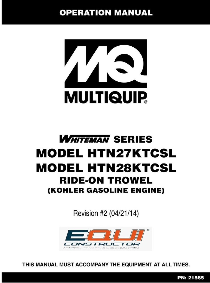
MULTIQUIP
MULTIQUIP Whiteman series User manual

MULTIQUIP
MULTIQUIP BS90C Guide

MULTIQUIP
MULTIQUIP Whiteman J36H55 User manual

MULTIQUIP
MULTIQUIP Whiteman JWN Series Guide
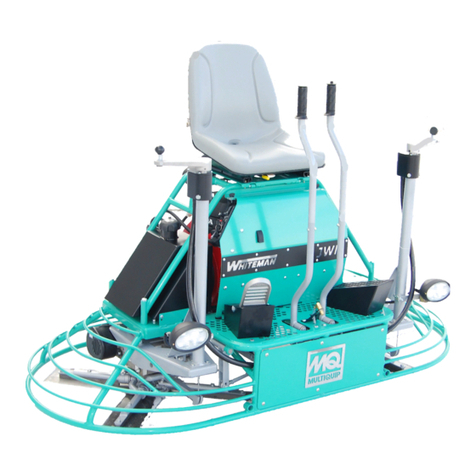
MULTIQUIP
MULTIQUIP Whiteman Series User manual

MULTIQUIP
MULTIQUIP JH55C Guide

MULTIQUIP
MULTIQUIP Whiteman J36H55 Guide

MULTIQUIP
MULTIQUIP Whiteman STXD6i User manual

MULTIQUIP
MULTIQUIP BH11C Owner's manual

MULTIQUIP
MULTIQUIP Whiteman series User manual

MULTIQUIP
MULTIQUIP Whiteman PRO Series User manual

MULTIQUIP
MULTIQUIP js36h55 Guide

MULTIQUIP
MULTIQUIP J-SERIES Guide
MULTIQUIP
MULTIQUIP Whiteman Series Guide

MULTIQUIP
MULTIQUIP J-36 Guide
MULTIQUIP
MULTIQUIP HHX User manual
MULTIQUIP
MULTIQUIP Whiteman CA5BC User manual
MULTIQUIP
MULTIQUIP WHITEMAN HDA Series User manual
Popular Trowel manuals by other brands

MBW
MBW MK8-75 Operator's safety and service manual
Wacker Neuson
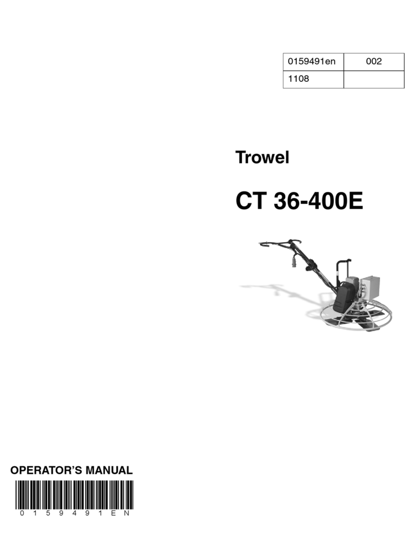
Wacker Neuson CT 36-400E Operator's manual
Atlas Copco
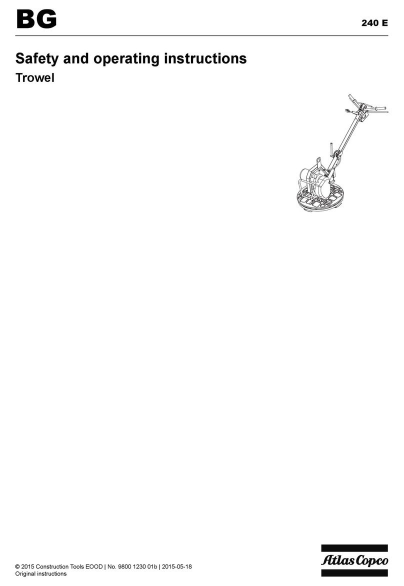
Atlas Copco BG 240 E Safety and operating instructions
MQ Multiquip
MQ Multiquip JS36/30H55DE Series Operation and parts manual
swepac
swepac TR 600P user manual

allen
allen PRO436DF Safety & operation manual
Wacker Neuson
Wacker Neuson CT 36 Operator's manual

Marshalltown
Marshalltown Speed Striker STRIKE45-L instructions

Wacker Neuson
Wacker Neuson CRT 48-31V Operator's manual

Northern Industrial
Northern Industrial tmt-36 User instruction manual
BOMAX
BOMAX BM-836H Operation manual

ENAR
ENAR TIFON 908 user manual
