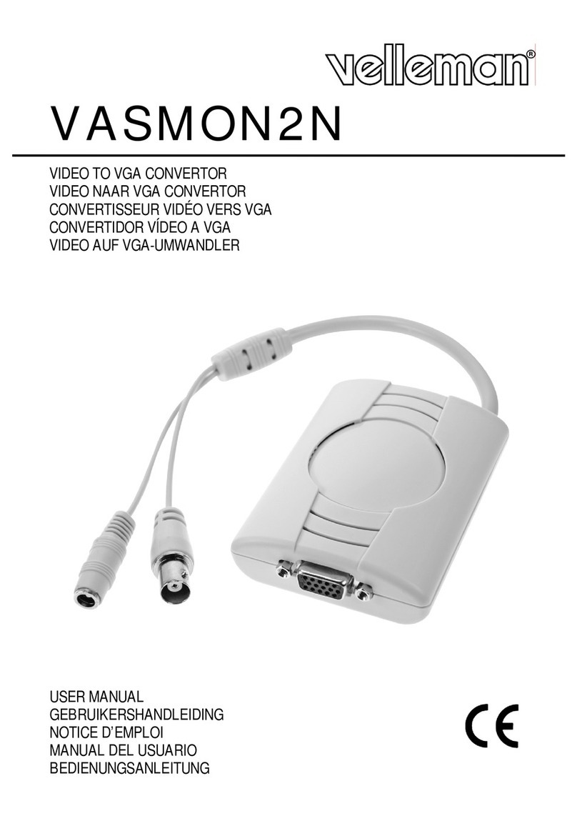
Cronologic xTDC4 User manual

Revision 1.57 as of 2018-01-02
Firmware 2 (build 834), Driver v1.2.0
cronologic GmbH & Co. KG
Jahnstrae 49
60318 Frankfurt am Main
Germany
cronologic
xTDC4
User Guide


Contents
1 Introduction 1
1.1 Features ......................................... 1
2 Hardware 3
2.1 Installing the Board .................................. 3
2.2 xTDC4 Inputs and Connectors ............................ 3
2.2.1 Connectors ................................... 3
2.3 xTDC4 Functionality .................................. 5
2.3.1 Grouping and Events ............................. 5
2.4 Performing a firmware update ............................. 5
2.5 Calibrating the Carry-Chain TDC .......................... 6
3 Driver Programming API 9
3.1 Constants ........................................ 9
3.2 Initialization ...................................... 9
3.2.1 Structure xtdc4 init parameters ........................ 9
3.3 Status Information ................................... 11
3.3.1 Functions for Information Retrieval ...................... 11
3.3.2 Structure xtdc4 static info ........................... 11
3.3.3 Structure xtdc4 param info .......................... 12
3.3.4 Structure xtdc4 fast info ............................ 13
3.4 Configuration ...................................... 13
3.4.1 Structure xtdc4 configuration ......................... 13
3.4.2 Structure xtdc4 trigger ............................ 15
3.4.3 Structure xtdc4 tiger block .......................... 15
3.4.4 Structure xtdc4 channel ............................ 16
3.5 Run Time Control ................................... 17
3.6 Readout ......................................... 17
3.6.1 Input Structure xtdc4 read in ......................... 17
3.6.2 Input Structure xtdc4 read out ........................ 18
3.7 Packet Format ..................................... 18
3.7.1 Output Structure crono packet ........................ 18
4 C Example 21
5 Technical Data 25
5.1 TDC Characteristics .................................. 25
5.2 Electrical Characteristics ............................... 25
5.2.1 Oscillator .................................... 25
5.2.2 Environmental Conditions for Operation ................... 25
5.2.3 Environmental Conditions for Storage .................... 25
5.2.4 Power Supply .................................. 26
5.2.5 Inputs ...................................... 26
i

Contents
5.3 Information Required by DIN EN 61010-1 ...................... 26
5.3.1 Manufacturer .................................. 26
5.3.2 Intended Use and System Integration .................... 26
5.3.3 Cooling ..................................... 27
5.3.4 Environmental Conditions ........................... 27
5.3.5 Inputs ...................................... 27
5.3.6 Recycling .................................... 27
ii

1 Introduction
The xTDC4 is a common-start time-to-digital converter. The timestamps of leading or trailing
edges of digital pulses are recorded. The xTDC4 produces a stream of output packets, each
containing data from a single start event, i.e. the relative timestamps of all stop pulses that
occur within the user defined range.
1.1 Features
4 channel common start TDC with 8 ps resolution
Standard Range: 218 µs (24 bit timestamp)
Extended Range: 13,975 µs
Bin size: approx. 13 ps
Double pulse resolution: 5 ns
Dead time between groups: none
Maximum start rate: 4 MHz
L0 FIFO: 15 words/channel
L1 FIFO: 512 words/channel
L2 FIFO: 10000 words
PCIe 1.1 x1 with 200 MB/s throughput
1


2 Hardware
2.1 Installing the Board
The xTDC4 board can be installed in any x1 (or higher amount of lanes) PCIe slot. Make sure
the PC is powered off and the main power connector is disconnected while installing the board.
2.2 xTDC4 Inputs and Connectors
2.2.1 Connectors
The inputs of the xTDC4 are located on the PCIe bracket. Figure 2.3 on page 4shows the
location of the start input S and the four stop inputs A to D. Lemo-00 connectors are used for
Stop A-D Start
Figure 2.1: Input connectors of the xTDC4 located on the PCIe bracket.
Lemo 00 connector
dc-offset[i]
DAC
+
-
Figure 2.2: Input circuit for each of the five input channels.
input connection. The inputs are AC-coupled and have an impedance of 50Ω - a schematic of
the input circuit is shown in Figure 2.2 on page 3. The digital trigger threshold can be adjusted
3

Pin Name
1, 2 GND
3, 4 external CLK in N, external CLK in P
5, 6 GND
7, 8 reserved/NC
9, 10 GND
11, 12 reserved/NC
13, 14 GND
15, 16 reserved/NC
17, 18 GND
19, 20 reserved/NC
21, 22 GND
23, 24 reserved/NC
25, 26 GND
27, 28 reserved/NC
29, 30 GND
31, 32 reserved/NC
33, 34 GND
Table 2.1: Pinout of connector C2.
in order to comply with a manifold of single ended signal standards enabling the acquisition of
positive or negative pulses.
B
C2
C1
S
S
C
D
A
C3
Figure 2.3: Schematic view of a xTDC4 board showing inter-board connectors C1 and C2.
Furthermore, three board interconnection connectors can be found at the top edge of the
board, as displayed in Figure 2.3 on page 4. Connector C1 (labelled J25 on the board) is
reserved for future use. The pinout of connector C2 (labelled J12 on the board) is given in
Table 2.1 and the pinout of connector C3 (labelled as J6 on the board) is depicted in Table 2.2.
cronologic GmbH & Co. KG 4 xTDC4 User Guide

Pin Name
1 +3.3 V
2 - 9 reserved/NC
10 GND
Table 2.2: Pinout of connector C3.
2.3 xTDC4 Functionality
The xTDC4 is a “classic” common start time-to-digital converter. It records the time difference
between leading or trailing edges on the start input and the stop inputs. Each stop channel A-D
can be enabled individually. The accuracy of the acquired timestamps is approx. 8 ps. The
timestamps are recorded in integer multiples of a bin size of 13.02083 ps (76.8 GHz). The data
acquisition can be limited to rising or falling signal transitions. Transitions of the input signals
are called hits. To reliably detect hits the signal has to be stable for at least 500 ps before and
after the edge. Between multiple hits on a stop channel a deadtime of approx. 5 ns occurs.
Within this deadtime further hits on the stop channel are reported with a coarse timestamp
only. The maximum trigger rate on the start channel is 4 MHz.
2.3.1 Grouping and Events
In typical applications a start hit is followed by a manifold of hits on e.g. a detector. The
hits recorded are managed in groups (which are called in some applications “events”). Figure
2.4 shows a corresponding timing diagram. The user can define the range of a group, i.e. the
time window within which hits on the stop channels are recorded, in software. Hits occurring
outside of that time window are discarded. The maximum recording range for a group is 218 µs.
Different ranges can be set for each of the 4 stop channels by setting corresponding channel.start
and channel.stop values in the channel configuration. The values need to be set as multiples of
13.02083 ps. A value of 768 corresponds, for example to a time of 10 ns.
Start
A
B
C
D
channel[i].start
channel[i].stop
Figure 2.4: Acquired hits are merged to groups as explained in the text.
2.4 Performing a firmware update
After installing the xTDC4 device driver, a firmware update tool is available. By choosing
“FirmwareGUI.exe” a firmware update can be performed. After invoking the application a
cronologic GmbH & Co. KG 5 xTDC4 User Guide

window as shown in Figure 2.5 will appear. The tool can be used for updating the firmware
and to create a backup of the on-board calibration data of the xTDC4 unit. If several boards
are present, the one which is going to be used can be selected in the upper left corner of the
window. Pressing the “Backup” buttons a backup of the firmware or the calibration data will be
created, respectively. In order to perform a firmware update, chose the “.cronorom”-file to used
by pressing “Browse”. The file contains the firmware data. By pressing “Flash” the firmware is
written to the board. “Verify” can be used to compare the firmware data stored on the xTDC4
to the one inside a file. “Flash All” and “Verify All” perform the corresponding operation on
all boards which are installed.
Figure 2.5: The firmware update and calibration data backup tool as provided with the xTDC4
device driver.
Important note: The new firmware will only be used after a power cycle, i.e. after switching
the PC (or Ndigo crate) off and back on. A simple reboot is not sufficient. Therefore the
information shown in the upper half of the application window does not change right after
flashing a new firmware.
2.5 Calibrating the Carry-Chain TDC
After each update of the xTDC4 firmware the Carry-Chain TDC has to be calibrated. Before
calibration make sure to power-cycle the system after updating the xTDC4 firmware. The
calibration is done with the tool “XTDC4Calibration.exe” (see Figure 2.6) which is available
after installing the xTDC4 device driver. Connect an external pulse signal to the Start and
channel inputs. The signal should be low active. The pulse low and high width has to be
at least 10ns each. Use “Calibrate” to start the calibration procedure. Follow the on-screen
instructions to gather calibration data on all channels. When all channels are calibrated use
“Write” to permanently store the calibration data in the xTDC4’s on-board flash.
cronologic GmbH & Co. KG 6 xTDC4 User Guide

Figure 2.6: The xTDC4 Carry Chain TDC calibration tool.
cronologic GmbH & Co. KG 7 xTDC4 User Guide

cronologic GmbH & Co. KG 8 xTDC4 User Guide

3 Driver Programming API
The API is a DLL with C linkage. There exists also a .Net wrapper.
The functions provided by the DLL are declared in xTDC4 interface.h.
3.1 Constants
#define xTDC4 CHANNEL COUNT 4
The number of analog input channels.
#define xTDC4 TIGER COUNT 5
The number of timing generators.
#define xTDC4 TRIGGER COUNT 16
The number of triggers. Two per analog input, one per digital input plus some specials.
3.2 Initialization
int xtdc4 close(xtdc4 device *device)
Finalize the driver for this device.
int xtdc4 count devices(int *error code,char **error message)
Return the number of boards that are supported by this driver in the system.
int xtdc4 get default init parameters(xtdc4 init parameters *init)
Sets up the standard parameters. Gets a set of default parameters for xtdc4 init(). This must
always be used to initialize the xtdc4 init parameter() structure.
xtdc4 device *xtdc4 init(xtdc4 init parameters *params,int *error code,char **error message)
Open and initialize the XTDC4 board with the given index. With error code and error message
the user must provide pointers where to buffers where error information should be written by
the driver.
Params is a structure of type xtdc4 init parameters that must be completely initialized.
3.2.1 Structure xtdc4 init parameters
int version
The version number. Must be set to XTDC4 API VERSION
int card index
The index in the list of XTDC4 boards that should be initialized.
There might be multiple boards in the system that are handled by this driver as reported by
9

xtdc4 count devices. This index selects one of them. Boards are enumerated depending on the
PCIe slot. The lower the bus number and the lower the slot number the lower the card index.
int board id
the global index in all cronologic devices.
This 8 bit number is filled into each packet created by the board and is useful if data streams
of multiple boards will be merged. If only XTDC4 cards are used this number can be set to the
card index. If boards of different types that use a compatible data format are used in a system
each board should get a unique id. Can be changed with int xtdc4 set board id(xtdc4 device
*device, int board id).
int64 buffer size[8]
The minimum size of the DMA buffer.
If set to 0 the default size of 16 MByte is used. For the xTDC4 only the first entry is used.
int buffer type
The type of buffer. Can be either allocated (only option currently) or physical.
#define XTDC4 BUFFER ALLOCATE 0
#define XTDC4 BUFFER USE PHYSICAL 1
int64 buffer address
The start address of the reserved memory.
The buffers will be allocated with the sizes given above. Make sure that the memory is large
enough.
int variant
Set to 0. Can be used to activate future device variants such as different base frequencies.
int device type
A constant for the different devices of cronologic CRONO DEVICE *.
Initialized by xtdc4 get default init parameters(). Must be left unchanged.
#define CRONO DEVICE HPTDC 0
#define CRONO DEVICE NDIGO5G 1
#define CRONO DEVICE NDIGO250M 2
#define CRONO DEVICE xTDC4 6
#define CRONO DEVICE TIMETAGGER4 8
int dma read delay
The update delay of the writing pointer after a packet has been send over PCIe. The base unit
is 16 to 32 ns. Should not be changed by the user.
int use ext clock
If set to 1 use external 10 MHz reference. If set to 0 use internal reference.
cronologic GmbH & Co. KG 10 xTDC4 User Guide

3.3 Status Information
3.3.1 Functions for Information Retrieval
The driver provides functions to retrieve detailed information on the type of board, its configu-
ration, settings and state. The information is split according to its scope and the computational
requirements to query the information from the board.
int xtdc4 get fast info(xtdc4 device *device,xtdc4 fast info *info)
Returns fast dynamic information.
This call gets a structure that contains dynamic information that can be obtained within a few
microseconds.
int xtdc4 get param info(xtdc4 device *device,xtdc4 param info *info)
Returns configuration changes.
Gets a structure that contains information that changes indirectly due to configuration changes.
int xtdc4 get slow info(xtdc4 device *device,xtdc4 slow info *info)
Returns slow dynamic information.
The data reported in this structure requires milliseconds to be obtained. The application should
only call it in situation where the program flow can cope with an interruption of that magnitude.
int xtdc4 get static info(xtdc4 device *device,xtdc4 static info *info)
Contains static information.
Gets a structure that contains information about the board that does not change during run
time.
3.3.2 Structure xtdc4 static info
This structure contains information about the board that does not change during run time. It
is provided by the function xtdc4 get static info.
int size
The number of bytes occupied by the structure.
int version
The version number.
int board id
ID of the board.
This value is passed to the constructor. It is reflected in the output data.
int driver revision
Encoded version number.
The lower three bytes contain a triple level hierarchy of version numbers, e.g. 0x010103 encodes
version 1.1.3.
A change in the first digit generally requires a recompilation of user applications. Change in the
second digit denote significant improvements or changes that don’t break compatibility and the
third digit changes with minor bug fixes and similar updates.
int firmware revision
Revision number of the FPGA configuration.
int board revision
cronologic GmbH & Co. KG 11 xTDC4 User Guide

Board revision number.
The board revision number can be read from a register. It is a four bit number that changes
when the schematic of the board is changed.
0: Experimental first board version. Labeled ”Rev. 1”
1: First commercial version. Labeled ”Rev. 2”
int board configuration
Describes the schematic configuration of the board.
The same board schematic can be populated in multiple variants. This is a four bit code that
can be read from a register.
int subversion revision
Subversion revision id of the FPGA configuration.
int chip id
16 bit factory ID of the TDC chip.
int board serial
Serial number.
With year and running number in 8.24 format. The number is identical to the one printed on
the silvery sticker on the board.
unsigned int flash serial high
high 32 bits of 64 bit manufacturer serial number of the flash chip.
unsigned int flash serial low
low 32 bits of 64 bit manufacturer serial number of the flash chip
int flash valid
If not 0 the driver found valid calibration data in the flash on the board and is using it.
3.3.3 Structure xtdc4 param info
This struct contains configuration changes provided by xtdc4 get param info().
int size
The number of bytes occupied by the structure.
int version
The version number.
double binsize Bin size (in ps) of the measured TDC data. The TDC main clock is running at
a frequency of 76.8 GHz resulting in a bin size of ≈13.0208ps.
int board id
Board ID.
The board uses this ID to identify itself in the output data stream. The ID takes values between
0 and 255.
int channels
Number of channels in the current ADC mode.
Can take values 1, 2 and 4.
int channel mask
Bit assignment of each enabled input channel.
cronologic GmbH & Co. KG 12 xTDC4 User Guide

Mask assigns a certain bit to each enabled input channel.
int64 total buffer
The total amount of DMA buffer in bytes.
3.3.4 Structure xtdc4 fast info
int size
The number of bytes occupied by the structure.
int version
The version number.
int tdc rpm
Speed of the TDC fan. Reports 0 if no fan is present.
int fpga rpm
Speed of the FPGA fan. Reports 0 if no fan is present.
int alerts
Alert bits from temperature sensor and the system monitor.
bit 0: TDC temperature alert (>141◦C)
int pcie pwr mgmt
int pcie link width
Number of PCIe lanes the card uses.
int pcie max payload
Maximum size in bytes for one PCIe transaction. Depends on system configuration.
3.4 Configuration
The device is configured with a configuration structure. The user should first obtain a structure
that contains the default settings of the device read from an on board ROM , than modify the
structure as needed for the user application and use the result to configure the device.
int xtdc4 configure(xtdc4 device *device, xtdc4 configuration *config)
Configures xtdc4 device.
int xtdc4 get current configuration(xtdc4 device *device, xtdc4 configuration *config)
Gets current configuration. Copies the current configuration to the specified config pointer.
int xtdc4 get default configuration(xtdc4 device *device, xtdc4 configuration *config)
Gets default configuration. Copies the default configuration to the specified config pointer.
3.4.1 Structure xtdc4 configuration
This is the structure containing the configuration information. It is used in conjunction with
xtdc4 get default configuration(),xtdc4 get current configuration() and xtdc4 configure().
It uses internally the structures xtdc4 tiger block and xtdc4 trigger.
cronologic GmbH & Co. KG 13 xTDC4 User Guide

int size
The number of bytes occupied by the structure.
int version
A version number that is increased when the definition of the structure is changed. The incre-
ment can be larger than one to match driver version numbers or similar. Set to 0 for all versions
up to first release.
int tdc mode
TDC mode. Can be grouped or continuous. Currently supported: grouped.
crono bool t start rising Rising or falling edge trigger.
double dc offset[XTDC4 CHANNEL COUNT + 1]
Set the switching voltage for the input channels S, A - D (see figure 3.1).
dc offset[0] : Start
dc offset[1 - 4] : A - D
Supported range is -1.32V to +1.18V. This should be close to 50% of the height of the input
pulse. Examples for various signaling standards are defined as follows
#define DC OFFSET P NIM +0.35
#define DC OFFSET P CMOS +1.18
#define DC OFFSET P LVCMOS 33 +1.18
#define DC OFFSET P LVCMOS 25 +1.18
#define DC OFFSET P LVCMOS 18 +0.90
#define DC OFFSET P TTL +1.18
#define DC OFFSET P LVTTL 33 +1.18
#define DC OFFSET P LVTTL 25 +1.18
#define DC OFFSET P SSTL 3 +1.18
#define DC OFFSET P SSTL 2 +1.18
#define DC OFFSET N NIM -0.35
#define DC OFFSET N CMOS -1.32
#define DC OFFSET N LVCMOS 33 -1.32
#define DC OFFSET N LVCMOS 25 -1.25
#define DC OFFSET N LVCMOS 18 -0.90
#define DC OFFSET N TTL -1.32
#define DC OFFSET N LVTTL 33 -1.32
#define DC OFFSET N LVTTL 25 -1.25
#define DC OFFSET N SSTL 3 -1.32
#define DC OFFSET N SSTL 2 -1.25
The inputs are AC coupled. Thus, the absolute voltage is not important for pulse inputs. It is
the relative pulse amplitude that causes the input circuits to switch. dc offset must be set to the
relative switching voltage for the input standard in use. If the pulses are negative, a negative
switching threshold must be set and vice versa.
xtdc4 trigger trigger[XTDC4 TRIGGER COUNT]
Configuration of the external trigger sources.
xtdc4 tiger block tiger block[XTDC4 TIGER COUNT] Configuration of the timing generator.
xtdc4 channel channel[XTDC4 CHANNEL COUNT]
Configure polaritiy, type and threshold for the TDC channels.
cronologic GmbH & Co. KG 14 xTDC4 User Guide

Lemo 00 connector
dc-offset[i]
DAC
+
-
Figure 3.1: Input circuit for each of the five input channels. Both inputs of the buffer are biased
at 1.32V by default.
xtdc4 lowres channel lowres channel[XTDC4 LOWRES CHANNEL COUNT]
Not applicable for xTDC4, only available for xTDC4-Sciex. Configure polarity, type and thresh-
old for the digital channels.
int auto trigger period
int auto trigger random exponent
Create a trigger either periodically or randomly. There are two parameters M= trigger period
and N= random exponent that result in a distance between triggers of Tclock cycles.
T= 1 + M+ [1...2N] (3.1)
0≤M < 232 (3.2)
0≤N < 32 (3.3)
There is no enable or reset as the usage of this trigger can be configured in the trigger block
channel source field.
3.4.2 Structure xtdc4 trigger
crono bool t falling
Triggers on falling edges.
crono bool t rising
Triggers on rising edges.
3.4.3 Structure xtdc4 tiger block
crono bool t enable
Activates timing generator.
crono bool t negate
Inverts output polarity. Default is set to false.
crono bool t retrigger
Enables/disables retrigger setting.
cronologic GmbH & Co. KG 15 xTDC4 User Guide
Table of contents

