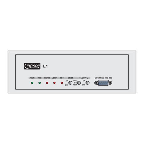
Cronyx Qlink-3000/2E1 Operating instructions

Version 1.5 – May 2005Copyright © 2003 -2005 Cronyx Engineering
CCC
Ministry of
Communications
of Russia
Multiplexing Modem
Qlink-3000
Models /2E1 and /E1-ETV
Installation and Operations Guide

Qlink-3000 Multiplexing modem
234567890 234567890 234567890 2 234567890 234567890 234567890 2 234567890 234567890 234567890 2 234567890 234567890 234567890 2 234567890 234567
234567890 234567890 234567890 2 234567890 234567890 234567890 2 234567890 234567890 234567890 2 234567890 234567890 234567890 2 234567890 234567
Copyright © 2003 -2005 Cronyx Engineering
2
Contents
Section 1. Introduction .......................................................5
1.1. Application .................................................................................................. 5
1.2. Model series ................................................................................................ 7
1.3. Order code ................................................................................................... 7
1.4. Technical specifications .............................................................................. 8
Link interface..................................................................................... 8
E1 interface (2048 kbit/s) .................................................................. 8
Ethernet interface............................................................................... 9
Emergency alarm interface................................................................ 9
Console port....................................................................................... 9
Control port SNMP ........................................................................... 9
Diagnostic modes ............................................................................ 10
Dimensions and weight ................................................................... 10
Electric power supply ...................................................................... 10
Operating conditions ....................................................................... 10
Section 2. Installation ....................................................... 11
2.1. Installation place requirements ................................................................. 11
2.2. Delivered items ......................................................................................... 11
2.4. Cable connections ..................................................................................... 11
Power supply connector .................................................................. 12
Ground terminal............................................................................... 13
Link connector ................................................................................. 13
E1 port connectors ........................................................................... 13
Ethernet port connector ................................................................... 14
SNMP port connector ...................................................................... 14
Console port connector.................................................................... 14
Emergency alarm connector ............................................................ 15
Section 3. Operations .......................................................16
3.1. Indicators................................................................................................... 16

Qlink-3000 Multiplexing modem
234567890 234567890 234567890 2 234567890 234567890 234567890 2 234567890 234567890 234567890 2 234567890 234567890 234567890 2 234567890 234567
234567890 234567890 234567890 2 234567890 234567890 234567890 2 234567890 234567890 234567890 2 234567890 234567890 234567890 2 234567890 234567
Copyright © 2003 -2005 Cronyx Engineering 3
3.2. Emergency alarms..................................................................................... 21
3.3. Device responses to emergencies ............................................................. 22
3.4. Loops......................................................................................................... 23
Normal mode ................................................................................... 23
E1 port loop (Port 0 loop) ............................................................... 24
E1 port tributary loop (Port 0 tributary loop) ................................. 24
Local loop on the link...................................................................... 25
Link remote loop ............................................................................. 25
3.5. Built-in BER tester ................................................................................... 26
Section 4. Control via the console port ..........................28
4.1. Upper level menu ...................................................................................... 28
4.2. Menu structure .......................................................................................... 30
Menu structure for models: ............................................................. 30
Qlink-3000/S-E1/ETV-SNMP-AC ................................................. 30
Qlink-3000/S-E1/ETV-SNMP-DC ................................................. 30
Menu structure for models: ............................................................. 30
Qlink-3000/S-2E1-SNMP-AC ........................................................ 30
Qlink-3000/S-2E1-SNMP-DC ........................................................ 30
4.3. “Statistics” menu ...................................................................................... 32
4.5. “Event counters” command ...................................................................... 34
4.6. “Loopback” menu ..................................................................................... 36
4.7. “Test” menu .............................................................................................. 36
4.8. “Configure” menu ..................................................................................... 38
“PCLK source” parameter............................................................... 39
“Mode” item .................................................................................... 39
“Port 0...” and “Port 1...” menus ..................................................... 39
“Alarm input” command ................................................................. 41
“SNMP” menu ................................................................................. 41
“Remote control” parameter............................................................ 42
“Factory settings” menu .................................................................. 43
4.9. “Link remote login” command ................................................................. 43
4.10. “Reset” command ................................................................................... 44
Section 5. Management via SNMP ..................................45
5.1. SNMP parameter settings ......................................................................... 46
5.2. Management information blocks (MIBs) ................................................. 47

Qlink-3000 Multiplexing modem
234567890 234567890 234567890 2 234567890 234567890 234567890 2 234567890 234567890 234567890 2 234567890 234567890 234567890 2 234567890 234567
234567890 234567890 234567890 2 234567890 234567890 234567890 2 234567890 234567890 234567890 2 234567890 234567890 234567890 2 234567890 234567
Copyright © 2003 -2005 Cronyx Engineering
4
Safety precautions
!An exclamation point enclosed in a triangle warns the user about important
operations and maintenance instructions for the device.
It is mandatory to observe the existing safety rules during installation, operations, and
technical maintenance of the device. Installation, technical maintenance, and repair
operations must be performed only by qualified and certified personnel. Installation,
technical maintenance, and repair operations must not be performed by the operator or
the user.
Certificate of Conformance
No. OS / 1-TM-317
The Qlink-3000 multiplexing modem equipment has been tested in the
Telecommunications Technical Device and System Testing Center of the “TsNIIS”
(Central Research and Development Institute of Telecommunications) of the Ministry
of Communications of the Russian Federation and is certified to comply with the
following technical requirements:
• RD 45.122-99 “Data transmission equipment designed for use as subscriber sets on
public physical communication links. Technical requirements”;
• RD 45.176-2001 “Communication equipment implementing frame switching in the
local network at the data link layer. Technical requirements”
• GOST R ISO 9001-96.
The Qlink-3000 multiplexing modem equipment is approved for use in the interlinked
communication network in Russia as subscriber sets for data transmission over non-
superimposed physical communication links.
CCC
Ministry of
Communications
of Russia

Qlink-3000 Multiplexing modem
234567890 234567890 234567890 2 234567890 234567890 234567890 2 234567890 234567890 234567890 2 234567890 234567890 234567890 2 234567890 234567
234567890 234567890 234567890 2 234567890 234567890 234567890 2 234567890 234567890 234567890 2 234567890 234567890 234567890 2 234567890 234567
Copyright © 2003 -2005 Cronyx Engineering 5
Section 1. Introduction
1.1. Application
Qlink-3000 – is a modem family for physical links, designed to operate over a single twisted
pair. Models equipped with two data ports (/2E1 and /E1-ETV) include the multiplexing
device and allow transmission of two independent data streams over a single twisted pair.
Device structural diagram is presented on the figure:
Port 0
E1 (G.703, G.704)
Port 1
E1 (G.703, G.704) or
Ethernet 10/100BaseT
(Ethernet 10BaseT)
Multi-
plexer
SHDSL
transceiver
SNMP port
Console port Processor
Maximum data transmission rate is 2304 kbit/s (36 x 64 kbit/s). Maximum transmission
distance depends on the data transmission rate in the link. The maximum link length for
the 26 AWG (0.4 mm) cable is given in the following table:
knilehtnietaratadlacisyhP etarnoissimsnartataD htgnelelbacmumixaM
s/tibk0232 s/tibk4032 mk0.4
s/tibk487 s/tibk867 mk4.5
s/tibk272 s/tibk652 mk6.7
The picture shows the diagrams of the item's use:
Port 1 (Ethernet)
Port 0 (E1)
Ethernet (SNMP)
Port 1 (Ethernet)
Port 0 (E1)
Qlink-3000
Ethernet Hub
/
Switch
Qlink-3000
Telephone
exchange
Router
Physical line
("copper pair")
Telephone
exchange
Ethernet
network

Qlink-3000 Multiplexing modem
234567890 234567890 234567890 2 234567890 234567890 234567890 2 234567890 234567890 234567890 2 234567890 234567890 234567890 2 234567890 234567
234567890 234567890 234567890 2 234567890 234567890 234567890 2 234567890 234567890 234567890 2 234567890 234567890 234567890 2 234567890 234567
Copyright © 2003 -2005 Cronyx Engineering
6
Main Qlink-3000 multiplexing modem characteristics:
• transmission of two data streams over a two-wire physical link for up to 10 km
distance;
• compliance with ITU-T standards G.703, G.704, G.706, G.991.2, and IEEE 802.3;
• local and remote loops;
• Built-in Bit Error Rate Tester (BER tester);
• RS-232 console port;
• remote control and monitoring over the SNMP protocol via a separate Ethernet port;
• emergency alarms (“dry” contacts of relay);
• design for mounting in a 19” rack (1U);
• built-in power supply unit for AC (176-264 V, 50 Hz) or DC (36-72 V) power
source.
The device may be controlled via the RS-232 interface using an ASCII terminal, or via
Ethernet using the SNMP protocol.
Indicators on the device's front panel show link status, enabled loops and enabled testing
mode. The built-in BER-tester allows measuring error rate in the link path. The
measurements are performed using fixed or pseudo-random code according to the O.151
recommendation (the pattern length is 215-1=32767 bits).
In order to test links in case when there are no personnel at the remote end of the link,
there is a remote login capability (to control the remote device from the console port of
the local device). Commands are transmitted to the remote device via an additional
service channel. At user's request remote configuration parameter changes may be
prohibited.
The device is equipped with an emergency alarm relay, the “dry” contacts of which may
switch on an external device to call the operations personnel.
The multiplexing modem has the capability of firmware upgrades. The instructions for
upgrading the firmware may be found at the www.cronyx.ru website.

Qlink-3000 Multiplexing modem
234567890 234567890 234567890 2 234567890 234567890 234567890 2 234567890 234567890 234567890 2 234567890 234567890 234567890 2 234567890 234567
234567890 234567890 234567890 2 234567890 234567890 234567890 2 234567890 234567890 234567890 2 234567890 234567890 234567890 2 234567890 234567
Copyright © 2003 -2005 Cronyx Engineering 7
1.2. Model series
The Qlink-3000 multiplexing modem has two data ports, one of which (Port 0) has an
E1 interface (G.703, G.704), and the other may be E1, Ethernet 10/100Base-T, digital
V.35 port, or a universal port (V.35, RS-530, RS-232 or X.21).
The multiplexing modem may also be equipped with an additional Ethernet 10Base-T
port for control over the SNMP protocol.
Additionally, the Qlink-3000 family includes modems with a single data port with a E1,
Ethernet 10/100Base-T, V.35 interface or a universal interface (V.35, RS-530, RS-
232, X.21).
All Qlink-3000 family modems are compatible with each other, i.e. there may be a
single model on one end of the link, and another model on the other.
1.3. Order code
Qlink-3000
Qlink-3000 / S - E1/ETV-SNMP-AC
Model:
Design:
S - 1U for a 19" rack
B - desktop
Data port(s):
2E1 - two E1 ports
E1-ETV - E1 and Ethernet (10/100Base-T)
E1-V - E1 and V.35
E1-M - E1 and V.35/RS-530/RS-232/X.21
E1 - single E1 port
ETV - single Ethernet port (10/100Base-T)
V - single V.35 port
M - single V.35/RS-530/RS-232/X.21 port
Power supply
220VAC
36...72VDC
or 40...60VDC
Control over SNMP

Qlink-3000 Multiplexing modem
234567890 234567890 234567890 2 234567890 234567890 234567890 2 234567890 234567890 234567890 2 234567890 234567890 234567890 2 234567890 234567
234567890 234567890 234567890 2 234567890 234567890 234567890 2 234567890 234567890 234567890 2 234567890 234567890 234567890 2 234567890 234567
Copyright © 2003 -2005 Cronyx Engineering
8
1.4. Technical specifications
Link interface
Link requirements .......................................... Unloaded twisted pair
Link data rate.................................................. 208 kbit/s to 2320 kbit/s
Link length ..................................................... Up to 10 km with a 0.6 mm wire strand
diameter,
up to 7.6 km with a 0.4 mm wire strand
diameter
Connector ....................................................... RJ type (female, 8 pins)
Encoding......................................................... TC-PAM
Transmission path synchronization................ Internal (from an internal clock-pulse
oscillator)
From Port (from the receiving path of
the E1 port)
Overvoltage protection ................................... SIDACtor
Overcurrent protection ................................... Fuse
E1 interface (2048 kbit/s)
Connector ....................................................... RJ-48 (female)
Link impedance .............................................. 120 Ohms, balanced (twisted pair)
Cycle structure................................................ according to G.704, or transparent stream
transmission (Unframed G.703)
Signal level at the receiver input.................... 0 to -43dB, up to 2 km over 22AWG
(0.6 mm) twisted pairs
Jitter attenuator ................................................ in the receiver path
Data encoding................................................. HDB3
Error detection ................................................ Bipolar violation
Overvoltage protection ................................... TVS
Overcurrent protection ................................... Fuse

Qlink-3000 Multiplexing modem
234567890 234567890 234567890 2 234567890 234567890 234567890 2 234567890 234567890 234567890 2 234567890 234567890 234567890 2 234567890 234567
234567890 234567890 234567890 2 234567890 234567890 234567890 2 234567890 234567890 234567890 2 234567890 234567890 234567890 2 234567890 234567
Copyright © 2003 -2005 Cronyx Engineering 9
Ethernet interface
Interface type .................................................. Ethernet 100Base-T
Connector type ............................................... RJ-45 (female)
Bandwidth ...................................................... 64 to 2304 kbit/s
Operating mode .............................................. 100 Mbps Full-duplex,
100 Mbps Half-duplex,
10 Mbps Full-duplex,
10 Mbps Half-duplex,
or Autonegotiation
(automatic selection)
LAN table size................................................ 15000 MAC-addresses
Maximum frame size...................................... 4224 bytes, including
MAC-layer header
Protocols ......................................................... Transparent or
Cisco-HDLC bridging IEEE protocol,
set automatically
Emergency alarm interface
Connector type ............................................... DB-9 (female)
Relay contact current...................................... Up to 600 mA
Relay contact voltage ..................................... Up to 110 VDC or 125 VAC
Console port
Interface type, ................................................. RS-232 DCE connector, DB-9 (female)
Data transfer protocol..................................... Asynchronous, 9600 bit/s,
8 bits/character, 1 stop bit, no parity
Modem signals ............................................... DTR, DSR, CTS, RTS, CD
Control port SNMP
Interface type .................................................. Ethernet 10Base-T
Connector ....................................................... RJ-45

Qlink-3000 Multiplexing modem
234567890 234567890 234567890 2 234567890 234567890 234567890 2 234567890 234567890 234567890 2 234567890 234567890 234567890 2 234567890 234567
234567890 234567890 234567890 2 234567890 234567890 234567890 2 234567890 234567890 234567890 2 234567890 234567890 234567890 2 234567890 234567
Copyright © 2003 -2005 Cronyx Engineering
10
Diagnostic modes
Loops .............................................................. Local, remote
Error rate control ............................................ Built-in
Control ............................................................ Via the RS-232 control port,
via the SNMP interface, or from a
remote device
Dimensions and weight
Design............................................................. For mounting in a 19”rack, height 1U
Size ................................................................. 444 mm x 262 mm x 44 mm
Weight............................................................. 3.4 kg
Electric power supply
176–264 VAC, 50 Hz
36–72 VDC
Power consumption ........................................ Not more than 12.5 W
Operating conditions
Temperature .................................................... 0 to 50 °C
Relative humidity ........................................... Up to 80%, no condensation

Qlink-3000 Multiplexing modem
234567890 234567890 234567890 2 234567890 234567890 234567890 2 234567890 234567890 234567890 2 234567890 234567890 234567890 2 234567890 234567
234567890 234567890 234567890 2 234567890 234567890 234567890 2 234567890 234567890 234567890 2 234567890 234567890 234567890 2 234567890 234567
Copyright © 2003 -2005 Cronyx Engineering 11
Section 2. Installation
2.1. Installation place requirements
The device must be grounded before switching on, there is a ground terminal screw on
the front panel provided for this purpose.
When installing the multiplexing modem, allow for at least 10 cm of free space next to
the front panel for interface cable connections.
The ambient temperature must be 0 to +50 °C at 80% humidity, no condensation.
2.2. Delivered items
Delivered items include:
• Qlink-3000 unit – 1 pc.;
• bracket for mounting the Qlink-3000 unit in a 19” rack – 2 pcs.;
• self-adhesive stand for the Qlink-3000 unit – 4 pcs.;
• power supply cable (for the AC model) – 1 pc;
• removable part of the power supply connector terminal unit
(for the DC model) – 1 pc.;
• user's guide –1 pc.
2.4. Cable connections
The front panel of the multiplexing modem contains connectors for connecting physical
links, E1 link(s), Ethernet link, SNMP control link, console, emergency alarm and power
supply.

Qlink-3000 Multiplexing modem
234567890 234567890 234567890 2 234567890 234567890 234567890 2 234567890 234567890 234567890 2 234567890 234567890 234567890 2 234567890 234567
234567890 234567890 234567890 2 234567890 234567890 234567890 2 234567890 234567890 234567890 2 234567890 234567890 234567890 2 234567890 234567
Copyright © 2003 -2005 Cronyx Engineering
12
E1 port
(Port 0)
Ethernet port
(Port 1) SNMP port
Emergency
alarm
Console
Link Grounding Power supply
SNMP port
Emergency
alarm
Console
Link Grounding Power supply
E1 port
(Port 0)
E1 port
(Port 1)
Front panel connector locations for Qlink-3000/S-2E1-SNMP model
Power supply connector
A standard mains connector is used to connect the AC power supply cable (for the “AC”
model). The power supply cable is supplied with the device.
To connect the DC power supply cable (for the “DC” model), the power supply connector
is used, shown below (view from multiplexer's front panel side):
+ 48 VDC- 48 VDC
Connected to the chassis
The corresponding removable part of the terminal unit of the power supply connector is
supplied with the device.
Front panel connector locations for Qlink-3000/S-E1/ETV-SNMP model

Qlink-3000 Multiplexing modem
234567890 234567890 234567890 2 234567890 234567890 234567890 2 234567890 234567890 234567890 2 234567890 234567890 234567890 2 234567890 234567
234567890 234567890 234567890 2 234567890 234567890 234567890 2 234567890 234567890 234567890 2 234567890 234567890 234567890 2 234567890 234567
Copyright © 2003 -2005 Cronyx Engineering 13
Ground terminal
There is a M4 screw on the front panel for device grounding.
!Before switching the device on, and before connecting other cables, the
multiplexer unit must be grounded properly.
Link connector
The RJ type connector (8 pins) is used for link connection:
1-not used
2-not used
3-not used
4- Line A
5- Line B
6-not used
7-not used
8-not used
1 8
E1 port connectors
The RJ-48 connector is used for E1 link connections:
1 - Input A
2 - Input B
3 - not used
4 - Output A
5 - Output B
6 - not used
7 - not used
8 - not used
1 8

Qlink-3000 Multiplexing modem
234567890 234567890 234567890 2 234567890 234567890 234567890 2 234567890 234567890 234567890 2 234567890 234567890 234567890 2 234567890 234567
234567890 234567890 234567890 2 234567890 234567890 234567890 2 234567890 234567890 234567890 2 234567890 234567890 234567890 2 234567890 234567
Copyright © 2003 -2005 Cronyx Engineering
14
Ethernet port connector
The RJ-45 female socket is used to connect the Ethernet port (10/100Base-T, IEEE
802.3 ) when operating using the remote bridge protocol:
1 - TX+ (output)
2 - TX (output)
3 - RX+ (input)
4 - not used
5 - not used
6 - RX (input)
7 - not used
8 - not used
1 8
Use direct cable for connection to the Ethernet switch.
SNMP port connector
An RJ-45 female socket is used for Ethernet port connection (10Base-T, IEEE 802.3
standard) for control over the SNMP protocol, shown above (see “Ethernet” port
connector”).
Use direct cable for connection to the switch.
Console port connector
ADB-9 (female) connector is used for console connection. The console port has a standard
RS-232 DCE interface, and utilizes the following settings: asynchronous mode, 9600
baud speed, 8 bits/symbol, 1 stop bit, no parity. Use a direct cable for connection to a PC
COM port.
!An RTS signal from the controlling terminal to the device port must be
provided when connecting the console.
It is recommended to use the following cable diagrams:

Qlink-3000 Multiplexing modem
234567890 234567890 234567890 2 234567890 234567890 234567890 2 234567890 234567890 234567890 2 234567890 234567890 234567890 2 234567890 234567
234567890 234567890 234567890 2 234567890 234567890 234567890 2 234567890 234567890 234567890 2 234567890 234567890 234567890 2 234567890 234567
Copyright © 2003 -2005 Cronyx Engineering 15
Emergency alarm connector
to Qlink3000 console
(DB9 male)
to Control terminal
Cable without modem control
GND 5
TXD 3
RXD 2
RTS 7
CTS 8
DTR 4
CD 1
GND
TXD
RXD
RTS
CTS
DTR
DSR
CD
Cable with modem control
GND 5
TXD 3
RXD 2
RTS 7
CTS 8
DTR 4
DSR 6
CD 1
GND
TXD
RXD
RTS
CTS
DTR
DSR
CD
to Qlink3000 console
(DB9 male)
to Control terminal
A DB-9 (female) connector is used for emergency alarm connection. The external input
sensor (pins 3 and 7) must be isolated from other electrical circuits. Pins 1, 2 and 6 are
reserved and must not be used.
3 - input contact
4 - connected to the middle
contact (9) during normal
operation, open during
errors
5 - open during normal operations,
connected to the middle
contact (9) during errors
7 - common wire (GND)
8 - common wire (GND)
9 - middle contact
Emergency alarm
circuits
Normal state shown
External input sensor
(user-supplied equipment)
5 4 3 2 1
8 79 6
+5 V

Qlink-3000 Multiplexing modem
234567890 234567890 234567890 2 234567890 234567890 234567890 2 234567890 234567890 234567890 2 234567890 234567890 234567890 2 234567890 234567
234567890 234567890 234567890 2 234567890 234567890 234567890 2 234567890 234567890 234567890 2 234567890 234567890 234567890 2 234567890 234567
Copyright © 2003 -2005 Cronyx Engineering
16
Section 3. Operations
3.1. Indicators
The front panel contains indicators, showing the status of the device. The list of indicators
and their functions are specified below in the text.
Qlink-3000/S-2E1-SNMP front panel
TST
SNMP
1 2 43
LINK
CONSOLE ALARM
7 8
PWR
PORT 0 PORT 1
65
Qlink-3000/S-E1/ETV-SNMP front panel
TST
SNMP
1 2 43
LINK
CONSOLE ALARM
7 8
PWR
PORT 0
PORT 1
91
0
6
5
1
2
1
1
1Power indicator (PWR)
The power indicator lights green when power supply is on.
2BER tester indicator (TST)
The indicator lights if the BER tester is switched on. The color determines the testing
results: green - testing is performed without errors, red - test pattern not detected, or
errors detected during testing. When the BER tester is switched off, the TST indicator
does not light.
3E1 port status and mode indicator (E1-LOC)

Qlink-3000 Multiplexing modem
234567890 234567890 234567890 2 234567890 234567890 234567890 2 234567890 234567890 234567890 2 234567890 234567890 234567890 2 234567890 234567
234567890 234567890 234567890 2 234567890 234567890 234567890 2 234567890 234567890 234567890 2 234567890 234567890 234567890 2 234567890 234567
Copyright © 2003 -2005 Cronyx Engineering 17
This indicator shows the status and the mode of the E1 port. The color shows the port
status: green - no errors (OK), red - no link signal (LOS) or error (AIS, LOF, LOMF).
The E1 port operating mode is shown by blinking: no blinking - normal operation,
blinks (single flashes) - the BER tester is enabled on the port tributary or loop is enabled
for the port, blinks (continuously) - loop is enabled on the port tributary. If the port is
disabled, then the corresponding E1-LOC indicator is extinguished. The table contains
the possible states of the E1-LOC indicator:
Color Blinking Description
Does not light Port disabled.
Green No Normal operation (status = OK, local loop and
port tributary loop disabled, BER tester
on the port tributary disabled).
Green Single Port status = OK, BER tester enabled on port tributary
flashes tester, or the local loop is enabled towards the G.703
link.
Red No No link signal G.703 (LOS). Local loop and port tributary
loop disabled, BER tester on port tributary disabled.
Red Single No link signal G.703 (LOS). BER tester
blinks enabled on port tributary BER or local
loop enabled towards G.703 link.
Red Flashes If the E1-REM indicator flashes red,
the port tributary loop is enabled. If the E1-REM indicator
does not blink, then there is signal in the link, but either
the AIS alarm indication signal is received, or
Loss Of Frame (LOF) or Loss of MultiFrame
synchronization (LOMF) found.
4Remote E1 port status and mode indicator (E1-REM)
This indicator shows the status and the mode of the remote E1 port. If the indicator is
green, then there are no errors on the remote side, and red indicates error (FARLOF - the
remote side transmits the alarm indication signal (bit A of the zero timeslot). The E1-
REM flashes red, if the tributary loop is enabled on the port tributary. If the port disabled
or there is no information from the remote device (for example, when operating in the
unframed mode), then the corresponding E1-REM indicator does not light. The table
contains the possible states of the E1-REM indicator:
Color Blinking Description
Does not light Port disabled or no information from the remote device.

Qlink-3000 Multiplexing modem
234567890 234567890 234567890 2 234567890 234567890 234567890 2 234567890 234567890 234567890 2 234567890 234567890 234567890 2 234567890 234567
234567890 234567890 234567890 2 234567890 234567890 234567890 2 234567890 234567890 234567890 2 234567890 234567890 234567890 2 234567890 234567
Copyright © 2003 -2005 Cronyx Engineering
18
Green No Normal operation (no alarm indication signal from the
remote).
Red No Alarm indication signal received from the remote
(bit A of the zero timeslot).
Red Single Loss of the G.703 signal in the link (LOS),
alarm indication signal (AIS) received, no frame (LOF)
or multiframe (LOMF) synchronization. BER tester is
enabled on port tributary or local loop enabled towards
the G.703 link.
Red Blinks Port tributary loop enabled (in this case the
E1-LOC indicator continuously flashes red).
5SHDSL link status and mode indicator (LINK-LOC)
This indicator shows the status and the mode of the SHDSL link. The color shows the
port status: green - connection established, no errors (OK), red - no connection or error
present (CRC anomaly, LOSW defect, Loop attenuation defect, SNR margin defect,
LOSW failure). The SHDSL port operating mode is indicated by blinking: does not
blink - normal operation, blinks (single flashes) - local loop or BER tester is enabled.
The table contains possible LINK-LOC indicator states:
Color Blinking Description
Green No Normal operation (connection established,
no errors, local loop and testing
mode disabled).
Green Single Port status = OK, BER tester or local loop
flashes enabled on the link.
Red No Connection not established (connection activation)
Local loop and testing disabled.
Red Single Connection not established or errors in the link
flashes (CRC anomaly, LOSW defect, Loop attenuation
defect, SNR margin defect, LOSW failure), the built-in
BER tester or local loop enabled on the link.
Red Blinks Connection established, but there are errors in the link
continuously (CRC anomaly, LOSW defect, Loop attenuation defect,
SNR margin defect, LOSW failure). Local loop and
link testing disabled.

Qlink-3000 Multiplexing modem
234567890 234567890 234567890 2 234567890 234567890 234567890 2 234567890 234567890 234567890 2 234567890 234567890 234567890 2 234567890 234567
234567890 234567890 234567890 2 234567890 234567890 234567890 2 234567890 234567890 234567890 2 234567890 234567890 234567890 2 234567890 234567
Copyright © 2003 -2005 Cronyx Engineering 19
6Remote SHDSL port status and mode indicator (LINK-REM)
This indicator shows the remote SHDSL port status and mode. If information about the
remote side is unavailable (connection not established, or service link does not operate
due to errors), then the LINK-REM indicator does not light. Color shows the port status:
green - connection established, no errors (OK), red - error (CRC anomaly, LOSW defect,
Loop attenuation defect, SNR margin defect, LOSW failure). The remote loop enabled
status is indicated by flashing: does not flash - normal operation, flashes (single flashes)
- remote loop enabled. The table contains possible LINK-REM indicator states:
Color Blinking Description
Does not light Remote device state unavailable (no
connection or errors in the link).
Green No Normal operation (connection established, no-
errors, remote loop disabled).
Green Single Connection activated, local loop
flashes enabled.
Red No Different link transmission rates set on local
and remote devices, or error on the remote side
(CRC anomaly, LOSW defect, Loop attenuation defect,
SNR margin defect, LOSW failure). Remote loop
disabled.
Red Single Error on the remote side (CRC anomaly, LOSW
flashes defect, Loop attenuation defect, SNR margin
defect, LOSW failure). Remote loop enabled.
7SNMP port activity indicator (SNMP-ACT)
The SNMP-ACT lights green during data reception/transmission over the SNMP port.
8SNMP port state indicator (SNMP-LINK)
The SNMP-LINK indicator does not light if the Ethernet cable is not connected to it. If
the cable is connected, then it lights green.
9Ethernet port mode indicator (ETH-FAST)
The indicator lights green, if the cable is connected to the Ethernet port, and the 100BaseT
mode is used. If the Ethernet cable is not connected to the port, or the 10BaseT mode is
used, then the ETH-FAST indicator does not light.

Qlink-3000 Multiplexing modem
234567890 234567890 234567890 2 234567890 234567890 234567890 2 234567890 234567890 234567890 2 234567890 234567890 234567890 2 234567890 234567
234567890 234567890 234567890 2 234567890 234567890 234567890 2 234567890 234567890 234567890 2 234567890 234567890 234567890 2 234567890 234567
Copyright © 2003 -2005 Cronyx Engineering
20
10 Ethernet port state indicator (ETH-LINK)
The ETH-LINK indicator does not light, if the Ethernet cable is not connected to the
port, and lights green if the cable is connected to the Ethernet port (the indicator flashes
during data reception and transmission).
11 Ethernet port error indicator (ETH-LOS)
The ETH-LOS indicator lights red, if the Ethernet cable is not connected to the port,
and flashes red during Ethernet bridge errors.
12 Ethernet port status indicator (ETH-STATUS)
The ETH-STATUS indicator does not light, if the port is disabled, lights green during
normal operation, flashes green if the BER tester is enabled on the port tributary.
This manual suits for next models
1
Table of contents
Other Cronyx Modem manuals
