crosscontrol CCpilot V1000 User manual

Revision: 1.0
2022-04-01
CCpilot V1000 and V1200
Technical Manual
www.crosscontrol.com

CCpilot V1000/V1200
Revision: 1.0
Technical Manual
2022-04-01
www.crosscontrol.com
2
1. Introduction
This technical manual provides important information regarding the CCpilot V1000 and V1200
product’s hardware and its basic usage, hereinafter referred to as CCpilot V1000/V1200.
The CCpilot V1000/V1200 are 10” and 12” display computer products featuring an i.MX
8QuadXPlus application processor.
For software and operating system specifics, please see additional documentation.
Revision history
Rev
Date
Author
Comments
PA1 2022-01-03 MLG
Draft
1.0
2022-04-01
FMG
Release version

CCpilot V1000/V1200
Revision: 1.0
Technical Manual
2022-04-01
www.crosscontrol.com
3
Contents
1. Introduction................................................................................................................................2
Revision history ...............................................................................................................................2
2. Product models .........................................................................................................................4
2.2. Document conventions .......................................................................................................4
2.3. Identification .........................................................................................................................4
2.4. Environmental resistance .....................................................................................................5
3. Product overview.......................................................................................................................6
3.1. Front side view.......................................................................................................................6
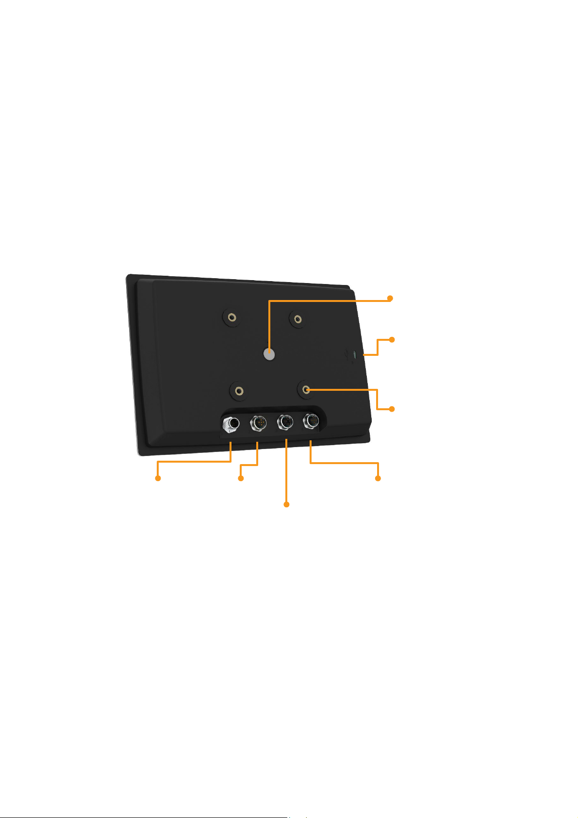
3.2. Rear side view .......................................................................................................................7
4. Mounting and handling ............................................................................................................8
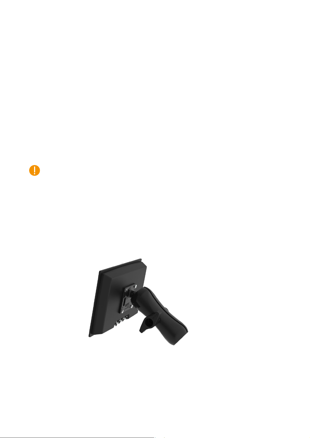
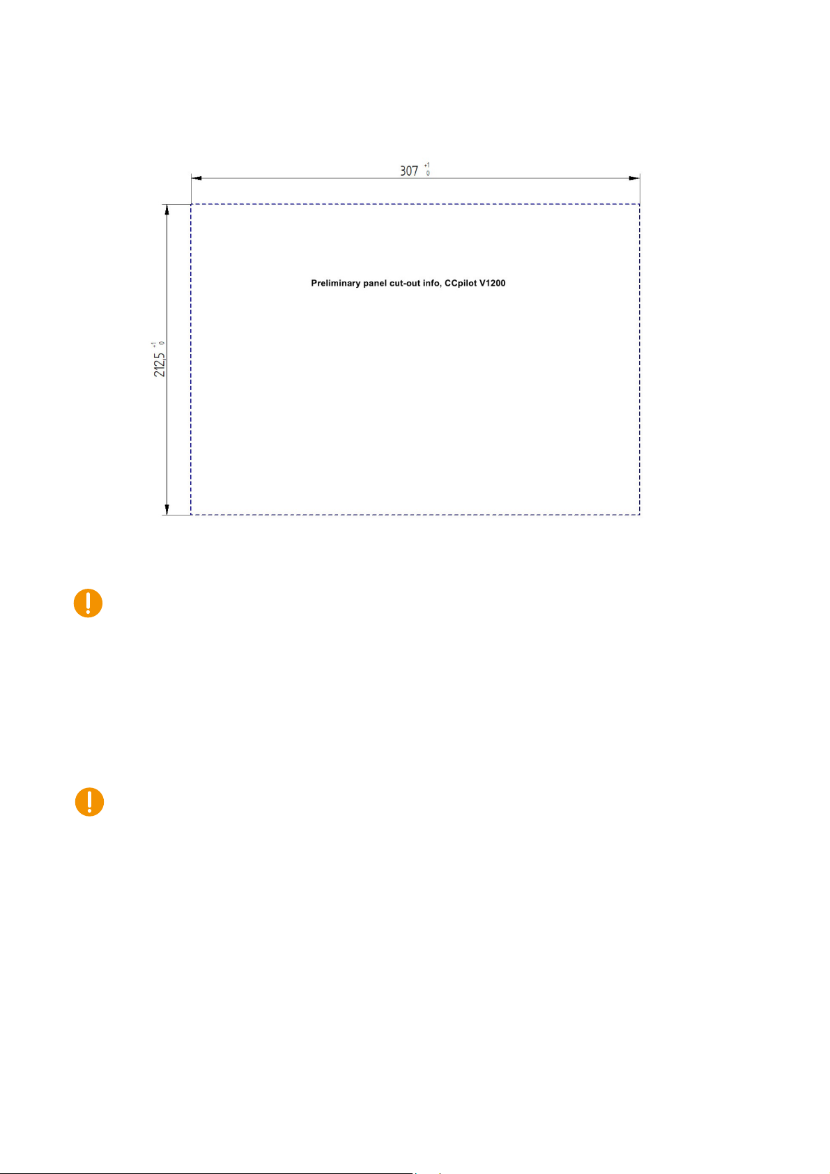
4.1. Mounting................................................................................................................................8
4.2. Connecting to power supply ............................................................................................10
4.3. Cable installation ................................................................................................................12
4.4. Special considerations .......................................................................................................13
4.5. Handling and maintenance..............................................................................................13
4.6. Transportation......................................................................................................................14
5. Basic operation........................................................................................................................15
5.1. Turning ON ...........................................................................................................................15
5.2. Turning OFF and suspending .............................................................................................15
5.3. Light sensor ..........................................................................................................................16
5.4. Using the touch screen ......................................................................................................17
5.5. Status notification ...............................................................................................................17
5.6. System related error codes................................................................................................17
5.7. Display related error codes ...............................................................................................18
6. Interface overview ..................................................................................................................20
6.1. Touch screen .......................................................................................................................20
6.2. Light sensor ..........................................................................................................................20
6.3. RGB status LED.....................................................................................................................20
6.4. Buzzer....................................................................................................................................20
6.5. CAN ......................................................................................................................................20
6.6. Ethernet................................................................................................................................21
6.7. USB ........................................................................................................................................21
6.8. Bluetooth and Wi-Fi.............................................................................................................21
7. Connectors ..............................................................................................................................22
7.1. M12 connectors ..................................................................................................................22
7.2. Connector 1 - Power and CAN M12 pinout ....................................................................23
7.3. Connector 2 - CAN M12 pinout ........................................................................................23
7.4. Connector 3 - Ethernet M12 pinout ..................................................................................24
7.5. Connector 4 - USB M12 connector pinout.......................................................................25
7.6. Connector 5 - USB-C...........................................................................................................26
8. Specifications ..........................................................................................................................26
8.1. Technical data....................................................................................................................26
8.2. Environmental specifications.............................................................................................29

CCpilot V1000/V1200
Revision: 1.0
Technical Manual
2022-04-01
www.crosscontrol.com
4
8.3. EMC specification...............................................................................................................29
8.4. Weight and dimensions......................................................................................................30
Technical support.........................................................................................................................32
Trademarks and terms of use ......................................................................................................33
2. Product models
This documentation is applicable for all CCpilot V1000/V1200 models. These models are:
•CCpilot V1000 2CAN.
•CCpilot V1000 4CAN Wi-Fi and Bluetooth.
•CCpilot V1200 2CAN.
•CCpilot V1200 4CAN Wi-Fi and Bluetooth.
These models share the same level of performance, hardware architecture, TFT, enclosure
and connectors. The PCB is the same for all versions but may be populated differently.
2.1.1. Customized models
The platform enables additional customization of hardware and software. Described herein are
the features included in product models described above. Additional features in customized
models will be documented separately.
Contact CrossControl for customization inquiries.
2.2. Document conventions
This document uses the following conventions:
Description
Appearance
Important information
Differences between product
models
(Exclamation symbol)
(Observe’ symbol)
Text formats used in this document are described in the table below:
Format
Use
Italics
Names, designations, and references
Bolded
Important information
2.3. Identification
Each device has identification labels with serial number, part number and revision which identifies
your unique device. This information is required when communicating with CrossControl regarding
Technical support and Service/Repair needs.

CCpilot V1000/V1200
Revision: 1.0
Technical Manual
2022-04-01
www.crosscontrol.com
5
Figure 1: Identification labels
2.4. Environmental resistance
The CCpilot V1000/V1200 products has been designed to manage tough environmental
demands. The focus, from design through components selection, has been to provide a
reliable and robust device.
Thorough testing has been performed to ensure compliance to a broad range of applicable
regulatory requirements and to meet user demands of a ruggedized product for machinery
control.
A complete list of the standards to which the product has been tested for compliance can be
found in chapters 8.2 and 8.3.

CCpilot V1000/V1200
Revision: 1.0
Technical Manual
2022-04-01
www.crosscontrol.com
6
3. Product overview
This chapter contains illustrations of the CCpilot V1000/V1200 showing the location of external
connectors, indicators etc. Connectors are described in more detail in chapter 7. Additional
mechanical information can be found in chapter 8.4.
3.1. Front side view
The devices feature either a 10” or 12” display with projected capacitive (PCAP) touch-sensor.
There is also a light sensor and an RGB status LED in the front. The light sensor enables
automatic dimming of the display and the RGB status LED shows operation modes or fault
indications.
Figure 2: CCpilot V1000/V1200 front side view
Light sensor
RGB status

CCpilot V1000/V1200
Revision: 1.0
Technical Manual
2022-04-01
www.crosscontrol.com
7
3.2. Rear side view
The rear side contains external connectors of type M12 and USB-C, mounting holes for either
a fastener in accordance with VESA 75 (M6) or custom bracket for panel mounting and a
GORE-TEX®membrane for ventilation.
Depending on exact product model the CCpilot V1000/V1200 product has either three or four
M12 connectors. The M12 connector for CAN channels 2-3 is only mounted on the product
instances holding 4 CAN interfaces.
Figure 3: CCpilot V1000/V1200 rear side view
GORE-TEX membrane,
under mount for added
protection
M12 connector 1
Power and CAN 1, 4
M12 connector 3
Ethernet
M12 connector 2
CAN 2-3
M12 connector 4
USB
USB-C
4 x M6 inserts for VESA75
mount

CCpilot V1000/V1200
Revision: 1.0
Technical Manual
2022-04-01
www.crosscontrol.com
8
4. Mounting and handling
This chapter contains recommendations for installation, handling and maintenance of the
product.
4.1. Mounting
CCpilot V1000/V1200 supports two different mounting methods, standardized VESA75 or a
panel mount. These two mounting methods are described separately below.
For both fastening methods, use the appropriate 4 pc. M6 button head screw of type MRT
(Torx) The recommended torque for the screws is 3.0-3.5 Nm. Using fluid locker or locking
washers (split ring, toothed lock, etc.) is required for proper mounting. Ensure that the M6
mounting screws are clean and dry before mounting.
Note that the depth of the threaded holes is 12mm. Be careful not to use too long screws which
may damage the device when tightened. It is also very important to use a fastening plate with
holes that are not larger in diameter than 7 mm so that the plate is flush with the threaded
inserts to avoid pulling out the threaded inserts from the unit.
4.1.1. VESA 75 mount
CCpilot V1000/V1200 can be mounted using a RAM mount, i.e. RAM-D-2461U, square base
2.25” ball mount and accessories of choice which allows adjustment of the display’s position
and angle. Screw length should be 16mm.
Figure 4: VESA 75 mount
4.1.2. Panel mount
Alternatively, the device can be mounted in a panel cut-out using a panel mounting bracket
(article number C000154-65)

CCpilot V1000/V1200
Revision: 1.0
Technical Manual
2022-04-01
www.crosscontrol.com
9
Figure 5: Mounting bracket
The mounting bracket is designed for a panel thickness of 1.5 - 3.0 mm. Panel cut out
dimensions are shown in the figure below. A drawing in DXF-format for precision cutting of
panels is available upon request. Screw length should be 12mm.
Figure 6: Panel cut-out CCpilot V1000

CCpilot V1000/V1200
Revision: 1.0
Technical Manual
2022-04-01
www.crosscontrol.com
10
Figure 7: Panel cut-out CCpilot V1200
Ensure that CCpilot V1000/V1200 is mounted to a smooth, flat surface. Fastening the unit to
an uneven surface may stress the enclosure, damage the outer flange, or possibly even flex
the circuit board inside, leading to a premature failure.
4.2. Connecting to power supply
This chapter describes how the CCpilot V1000/V1200 is preferably connected to the power
supply of the equipment it is installed in. The principle is the same for vehicular and stationary
installations.
Carefully read through the following sub-chapters. They are critical for designing and adapting
the electrical system of the equipment in which the CCpilot V1000/V1200 is installed.
Connector pinouts are found in chapter 7.
4.2.1. Wire gauge
Wire gauge for the power supply should be dimensioned with respect to the total load current,
the cable length required, and the worst-case voltage drop allowed, considering the minimum
operational voltage of the device.
•Current consumption of the CCpilot V1000/V1200 device is found in chapter 8.1.
•The wire gauge for the power supply is recommended to be at least 0.75 mm2/AWG 18 for
“normal” loads.

CCpilot V1000/V1200
Revision: 1.0
Technical Manual
2022-04-01
www.crosscontrol.com
11
4.2.2. External fuse
To prevent cable fire in case of short circuit, an external fuse must always be used when
powering the device from a high current capable power source, for example a vehicle battery.
•The fuse shall be located as close to the battery/power source as practically possible. A
recommendation is to place the fuse at a maximum distance of 15 cm (6 inches) from the
(+) terminal of the source.
•Fuse rating shall be dimensioned with respect to wire gauge, maximum current
consumption and the inrush current of the device. Refer to chapter 8.1 for fuse rating
details.
•As a guideline, a slow acting fuse with 2-3 A current rating should be used.
•Remember to also apply fusing for the on/off control wiring, see chapter 4.2.4.
4.2.3. External key switch signal
The device’s key switch signal should be connected to the positive supply line via the vehicle’s
ignition key switch.
•The wire gauge for the key switch signal shall be dimensioned to handle the total switch
current and the fuse type and rating shall be selected to prevent cable fire in case of
cabling short circuit.
•As a guideline, a slow acting fuse in the range of 100-500 mA for the key switch signal
should be sufficient for most practically usable wire gauge.
4.2.4. Application example
Below is an application example schematic of the CCpilot V1000/V1200 power supply
connection.
If the system has a main switch for completely disconnecting the battery (S1 in schematic
below), the device’s power supply and key switch signal shall be connected after the main
switch.
It is not recommended to disconnect the battery without shutting down the device first - since
doing so will immediately switch off all internal voltages, regardless of ongoing operations. Any
information which was not saved to flash memory will be lost when disconnecting the battery.
However, no physical damage will be caused to the device by disconnecting the battery.

CCpilot V1000/V1200
Revision: 1.0
Technical Manual
2022-04-01
www.crosscontrol.com
12
Figure 8: Schematic example for power supply installation of a CCpilot V1000/V1200 device
in a vehicle. The ignition switch (S2) can be shared by several devices (Device X, Y, …)
By connecting the power supply according to the example above, the CCpilot V1000/V1200
device will automatically start up when the key switch (S2) is closed and shut down when the
switch is opened.
Note that the on/off behaviour of the CCpilot V1000/V1200 described here is the default
configuration. Its response to the on/off signal may be altered using the CCAux API, see
chapter 5.1 for more details.
Be advised that the device consumes a small amount of power from the main supply also when
shutdown. Therefore, if the device has been attached for a long period of time without the
vehicle motor running, the battery may be drained, resulting in inability to start up the vehicle. A
main switch for disconnecting the device’s main supply is highly recommended in such
situations.
4.3. Cable installation
Cables should be installed in such a way that they do not run any risk of being damaged,
pinched or worn.
•Avoid excessive bending and twisting of cables.
•Use strain-relief on cables near the device to minimize stress on cables and connectors.
•Properly secure the connectors to give reliable contact and sealing and to avoid
unnecessary strain.
GND
1
2
4
F1
2-3 A
GND
BATTERY
S2
(Turnkey
switch)
M12
connector 1
:
:
F2
0.1-0.5 A
Device B
GND
Device C
GND
IMAX: 2.5 mA
Min 0.75 mm2/AWG 18
S1
(Main switch)
(on/off control)
Min 0.75 mm2/AWG18
Device A

CCpilot V1000/V1200
Revision: 1.0
Technical Manual
2022-04-01
www.crosscontrol.com
13
•Shielded cables are recommended and, in some cases, necessary to ensure reliable
communication and appliance with agricultural EMC standards.
4.3.1. Recommendations for cable shields
To achieve electromagnetic compliance and stable operation of the system, shielded cables
are required for Ethernet and USB interfaces.
4.4. Special considerations
To ensure proper and reliable operation, and to retain the device’s IP-classification, the below
recommendations must be followed:
•The device should be placed in a way that prevents direct and continuous exposure to
water or proximity to hot-air vents.
•To enable sufficient cooling, the device must be installed in a way that allows ambient air to
circulate around it. A clearance of at least 50 mm around the device is recommended.
•To maintain IP classification, all connectors must have a mating external connector
attached. Protective caps shall be used on all non-mated connectors. Please note that the
protective caps mounted on the connectors are for transportation protection only.
•The device has a ventilation membrane, refer to Figure 3 for the location. For proper
ventilation of the device, dirt and water must be prevented from accumulating and covering
the membrane. Be cautious not to insert objects which may puncture the membrane. Doing
so will violate the IP-classification and void the warranty of the device.
•Install the device and any cables attached in a way that they are not subject to excess
vibrations or other potentially harmful stress.
•Loose fasteners are a common cause for excessive vibration. Fasteners may come loose
due to improper mounting techniques such as omitting thread lockers (fluid locker or
locking washers) or by over/under-tightening. Proper tightening requires dry, clean
fasteners and a torque wrench.
•If the device is exposed to chemicals, water, dirt or other pollutants, it is recommended to
have it cleaned off as soon as possible. See chapter 4.5.1 for cleaning instructions.
4.5. Handling and maintenance
Handle the device with care and pay attention to the following handling instructions:
•Disconnect all cables to the device during welding or when performing other service to the
machine imposing a risk of damaging electronic devices.
•Service and repair to the device shall only be made by authorized personnel. If the device
is opened by unauthorized personnel, its warranty will be void.
•Scratches or other damages may occur to the display surface if it is exposed to sharp
objects, abrasives or heavy impacts. This must be avoided to increase the longevity of the
screen.

CCpilot V1000/V1200
Revision: 1.0
Technical Manual
2022-04-01
www.crosscontrol.com
14
•The internal eMMC flash storage has a limited number of write cycles. Therefore, it is
recommended that the amount of writing to flash is limited within software applications.1
•Always consider personal safety when installing and operating the product. For example,
in vehicle installations, CrossControl does not recommend that the product is being
actively operated by the driver when a risk of injury to people or damage to property is
present.
4.5.1. Cleaning
To ensure proper and reliable functionality over time, pay attention to the following cleaning
instructions and precautions:
•Wipe the device clean from dirt using a soft damp cloth, preferably of microfiber type.
Larger amount of dry dust may be swept off using a soft brush before wiping clean.
•Avoid using alkaline, alcoholic or other potentially adverse chemicals for cleaning as doing
so may damage the device. However, small amount isopropyl alcohol may be used for
removing harsh stains.
•Avoid spraying or by other means applying larger amount of water or alcohol directly to the
device. Instead, lightly dampen a cloth before using it for cleaning the device.
•After cleaning, make sure that the device surface is left dry.
•Never use high-pressure air, vacuum, water or steam to clean the device.
4.5.2. Real time clock battery
Time and date information is stored in a memory sustained by an internal back-up battery. The
battery is a 3V 1000mAh high operating temperature Poly-carbonmonofluoride Lithium battery.
The expected lifetime of the battery is approximately 20 years. The battery is not replaceable.
4.6. Transportation
When transporting the device, it is recommended to use the original packaging. Make sure that
protective caps are used on all non-mated connectors. The safe storage temperature range [-
40°C to +80°C] must be adhered to.
1The eMMC is used in pseudo SLC mode and implements both static and dynamic wear levelling to achieve the
best reliability. The number of program/erase cycles is between 20k to 60k depending on the manufacturer and
temperature. Our recommendation for the application software is to temporary cache in RAM and to write larger
chunks of data to the eMMC. This recommendation is not specific to eMMC but is applicable to all flash
memories.

CCpilot V1000/V1200
Revision: 1.0
Technical Manual
2022-04-01
www.crosscontrol.com
15
5. Basic operation
This section covers basic operation of the product such as start-up, shut down, suspend,
resume, display operation and status notification.
Observe that the behaviour of the external on/off control is user configurable in terms of:
•Enabling/disabling functionality
•Timing parameters
•Edge or level triggered
Notifications during start-up are indicated by the status LED or buzzer delivering different
patterns. The buzzer is used for audible operation alerts as well as for various error
notifications, see chapter 5.6 for error code details.
The status notification behaviour in the operational state of the device is configurable by user
applications. Described herein are the factory default behaviours of the on/off controls and the
status notification.
5.1. Turning ON
The CCpilot V1000/V1200 product can be started in different ways:
1. Connecting the external on/off control signal to a positive supply input (at or above
approximately 6V).
oWhen started this way, the on/off signal must remain asserted. De-assertion of this
signal will shut down the device unless configured otherwise.
2. It is possible to configure the device to automatically start up whenever external power is
applied (i.e. without using any on/off control).
a. Note that this function is disabled as factory default.
For resuming the device from suspend mode, see chapter 5.2.
While starting up the device, it will give a short beep and the status LED will flash with 2 Hz.
When the device enters operational state the status LED will stop flashing and be turned on.
5.2. Turning OFF and suspending
There are several ways to turn off the CCpilot V1000/V1200 device and also alternatives to
enter suspend mode instead of completely shutting down the device.
5.2.1. Shutting Down
There are two ways to shut down the device, provided that it is in normal operational state
when the action occurs:
1. By disconnecting the external on/off control for more than a specified time, i.e. using the
turn-key functionality.
oThe time-out is user configurable (default is set to 4 seconds).

CCpilot V1000/V1200
Revision: 1.0
Technical Manual
2022-04-01
www.crosscontrol.com
16
oIf the on/off signal is brought back high again while the device is shutting down, it
won’t restart automatically. A low-to-high transition must occur after the device has
fully shut down to make a restart.
2. By operating system shutdown requests.
To ensure that data is not lost nor the flash memory corrupted, it is recommended that all
necessary data be saved, and all programs closed before the device is shut down.
Note that the device won’t shut down from Suspend mode by these actions. See chapter 5.2.2
for details of Suspend mode and wakeup.
When performing any of the above, the CCpilot V1000/V1200 device will shut down.
5.2.2. Suspending/resuming
Suspending and resuming are a faster alternative to shutting down and starting up the device.
In suspend mode, the data remains in RAM memory and the device must be connected to
external power supply to maintain its state.
Suspend mode can be entered in two ways:
1. By disconnecting the external on/off control, for example using the turn key functionality.
oBy factory default, disconnecting the external on/off control is configured to shut-
down the device.
2. By selecting the operating systems suspend alternative.
Observe that the product current consumption in suspend mode is higher than in shut-down
mode.
To prevent a vehicles or machines battery from draining when the device is suspended, a user
configurable time-out can be set for how long the unit shall stay in suspend mode before it
automatically shuts down. The default suspend time-out is set to 60 minutes.
Resuming from suspend mode can be done by the following event:
1. A low-to-high transition of the external on/off control, for example using the turn-key
functionality.
Configuration of suspend and resume is done through the CCSettingsConsole application or
using the CCAux API. See the software guide for details.
5.3. Light sensor
The CCpilot V1000/V1200 contains a light sensor that can be used to automatically adjust the
display brightness, depending on the ambient light conditions. As depicted in Figure 2, the light
sensor is located in the lower right corner of the front surface. When automated dimming is
enabled, the level of sensitivity can be adjusted.
The screen brightness can also be manually controlled directly from user applications through
APIs.

CCpilot V1000/V1200
Revision: 1.0
Technical Manual
2022-04-01
www.crosscontrol.com
17
For proper operation it is important to keep the light sensor opening clean and unobstructed
visibility.
5.4. Using the touch screen
To reduce reflections when operating in very bright conditions, the touch screen’s protective
glass is covered with an anti-glare layer. Do not use any sharp or abrasive objects when
interacting with the touch screen.
Basic usage of the capacitive touch screen should be intuitive for most users. Note that the
touch screen is capable of handling multiple simultaneous touches.
5.5. Status notification
The CCpilot V1000/V1200 contains a status LED, in the front, used for notification while
starting up, shutting down or in other operational states. The buzzer may also be used for user
notifications. See Table 1 for a description of the status notification behaviour for different
operational states.
Table 1: LED and buzzer indication for different operational states
Operational state
LED indication
Buzzer notification
Device off
OFF
-
Power applied, device off
OFF
-
Starting up
Yellow flashing, 2 Hz
Short beep
Operating (started up)
Static green
-
Suspended
Yellow flashing, 0.2 Hz
-
Shutting down
Static yellow
-
Rebooting
Static yellow
Rescue mode, starting
Static orange
Short beep
Rescue mode, running
Green flashing, 2 Hz
-
OTG mode (OS update)
Yellow flashing, 0.5 Hz
-
Forced update mode (OS update)
Orange flashing, 0.5 Hz
-
SS firmware update mode
Static yellow
-
Observe that the status notification behaviour in both the start-up and operating states is
configurable by user applications running on the device.
5.6. System related error codes
The status LED in the front is also used for indicating system related error codes by emitting a
blue blinking pattern after shutdown of the device. The device may be started again when in
this mode, by the key switch signal. Depending on the nature of the error, the device may start
or go back into error indication.
When an error occurs, the device is immediately shut down and the error is reported by
blinking a specific number of times corresponding to an error code (see table of error codes).
The blinks will be in a continuous sequence of 1 Hz blinks, with a longer pause of two seconds
after the specific number of blinks, allowing the end user to count the number of blinks. Refer
to Figure 9 below for an example.

CCpilot V1000/V1200
Revision: 1.0
Technical Manual
2022-04-01
www.crosscontrol.com
18
Figure 9: Example of the blinking pattern for error code 3
When an error occurs, an error code is also immediately saved to persistent storage (FRAM). If
several errors occur before the device is shut down, only the code of the first error is saved and
reported. The error code in persistent storage can be read and cleared from a user application.
Refer to Table 2: CCpilot V1000/V1200 system related error codes for a complete listing of the
error codes.
The number of blinks is important information if the unit is sent in for service/repair.
Table 2: CCpilot V1000/V1200 system related error codes
Error code
Error code name
Likely problem cause
1
TEMP_ABOVE_MAX_ERROR
Temperature is above max limit
2
TEMP_BELOW_MIN_ERROR
Temperature is below min limit
3
TEMP_IMPOSSIBLE_VALUE_ERROR
PCBA temperature sensor
malfunction
4
TEMP_MEAS_TIMEOUT_ERROR
PCBA temperature sensor
malfunction
5
WD_RESET_ERROR
Watchdog timer reset
6
VMAIN_BELOW_LIMIT_ERROR
Main power supply voltage is
below min limit
7
VMAIN_ABOVE_LIMIT_ERROR
Main power supply voltage is
above max limit
8
MCU_HARD_EXCEPTION_ERROR
MCU hard fault exception
9
NVM_CORRUPTED_DATA_ERROR
Non-volatile memory data is
corrupted
5.7. Display related error codes
Unlike system related errors, display related errors are not indicated by the LED. When a
display related error occurs, an error code is immediately saved to persistent storage
(EEPROM). The error log in persistent storage can store up to 32 error codes and is readable
from the ccsystemreport application.
Refer to Table 3: CCpilot V1000/V1200 display related error codes for a complete listing of the
error codes.
The error log is important information if the unit is sent in for service/repair.
Table 3: CCpilot V1000/V1200 display related error codes

CCpilot V1000/V1200
Revision: 1.0
Technical Manual
2022-04-01
www.crosscontrol.com
19
Error code
Error code name
Likely problem cause
0
ERR_NO_ERROR
Default entry, log entry never written.
1 ERR_INVALID_LOG_ENTRY
Invalid log entry, i.e failed to read the
log entry from EEPROM.
2
-
-
3
-
-
4
ERR_LS_INIT
Failed to initialize light sensor.
5
ERR_LS_I2C
Failed to access light sensor over I2C.
6
ERR_EEPROM_INIT
Failed to initialize eeprom.
7 ERR_DISP_ROT_AT_STARTUP
Failed to set display rotation at startup
(V1000 only).
8
ERR_RCC
Failed to configure clocks.
9 ERR_TOUCH_I2C
Failed to access touch controller over
I2C.
10
ERR_TOUCH_NUM_CONTACTS
Max number of contacts exceeded.
11
ERR_HID_START_TRANS_FAILED
Failed to start a touch data transfer.
12
ERR_HID_RX_BUFF_OVERRUN
I2C HID receive buffer overrun.
13
ERR_HID_REPORT_BUFF_OVERRUN
Touch report buffer overrun.
14
ERR_MP_RX_BUFF_OVERRUN
MP I2C receive buffer overrun.
15
ERR_MP_TX_BUFF_OVERRUN
MP I2C transmit buffer overrun.
16
ERR_MP_RX_WR_BUFF_OVERRUN
MP write buffer overrun.
17 ERR_MP_CMD_INVALID
Invalid/unknown command sent from
MP.
18 ERR_LOG_INIT
Failed to read out error log from
EEPROM.
19 ERR_EEPROM_DEFAULTS
Failed to write parameter default
values to EERPOM.
20
ERR_EEPROM_PARAM_WRITE_FAILED
Failed to write EEPROM parameter.
21
ERR_EEPROM_PARAM_READ_FAILED
Failed to read EEPROM parameter.
22
ERR_BL_OFF_SEQ
Backlight OFF sequence failed.
23
ERR_BL_ON_SEQ
Backlight ON sequence failed.
24
ERR_TFT_EN_SEQ
TFT enable sequence failed.
25
ERR_TOUCH_EN_SEQ
Touch enable sequence failed.
26
ERR_DISP_OFF_SEQ
Display OFF sequence failed.
27
ERR_PARAM_BUFF_OVERRUN
EEPROM parameter buffer overrun.
28 ERR_I2C_CALLBACK
Failed to register callbacks for I2C
transfer.
29
ERR_HID_IRQ_TIMEOUT
Touch interrupt not cleared by MP.

CCpilot V1000/V1200
Revision: 1.0
Technical Manual
2022-04-01
www.crosscontrol.com
20
6. Interface overview
This section describes the various interfaces of the product. Main part of these interfaces can
be accessed via software APIs. These are described in more detail in the CCpilot
V1000/V1200 Software Guide.
6.1. Touch screen
The front panel contains a projective capacitive (PCAP) touch screen, which is capable of
handling multiple simultaneous touches.
6.2. Light sensor
There is a light sensor in the front panel used by user applications or used with the built-in
automated function for dimming of the display brightness.
For light sensor location, see Figure 2. Refer to the CCpilot V1000/V1200 Software guide for
details about accessing the light sensor data from within user applications.
6.3. RGB status LED
The CCpilot V1000/V1200 contains a status LED in the front used for notification while starting
up, shutting down or in other operational states.
6.4. Buzzer
The CCpilot V1000/V1200 has a built-in buzzer that can be used for audible notifications. The
buzzer is software controllable with configurable volume and frequency.
For buzzer location see Figure 3. See chapter 5.5 for buzzer notification events. Refer to the
CCpilot V1000/V1200 Software guide for details about controlling the buzzer from user
applications.
6.5. CAN
Depending on product model CCpilot V1000/V1200 has two or four CAN-FD ports that meets
CAN ISO 11898 2.0B (29-bit extended identifier) and supports bit rates up to 5 Mbps.
Two of the CAN channels are always present within the M12 connector 1 and the optional two
are present within the M12 connector 2.
Connector 1 houses channels 1 and 4, Connector 2 has channels 2 and 3, this is the same in
all models.
The second CAN channel in M12 connector 1 has the possibility for wake on CAN function.
Refer to the CCpilot V1000/V1200 Software guide for details.
Note that Internal EMI filters on CAN High/Low signals have a capacitance of 100 pF (typ)
which deviates from the ISO 11898 standard and implies some limitations on the CAN bus
topology (maximum bus length, number of CAN nodes etc.) when running at high bit-rates
(above 250 kbps).
The ports feature highly protected CAN transceivers which are tolerant for bus short-circuits to
main supply voltage and ground.
This manual suits for next models
1
Table of contents
Other crosscontrol Monitor manuals