crosscontrol CCpilot VI User manual

Revision: 2.0.0
2018-10-19
CCpilot VI
Technical Manual
www.crosscontrol.com

CCpilot VI
Revision: 2.0.0
Technical Manual
2018-10-19
www.crosscontrol.com
2
Contents
Revision history ..................................................................................................................................3
1. Introduction ..................................................................................................................................4
1.1. Product models.......................................................................................................................... 4
1.2. Document conventions ........................................................................................................... 4
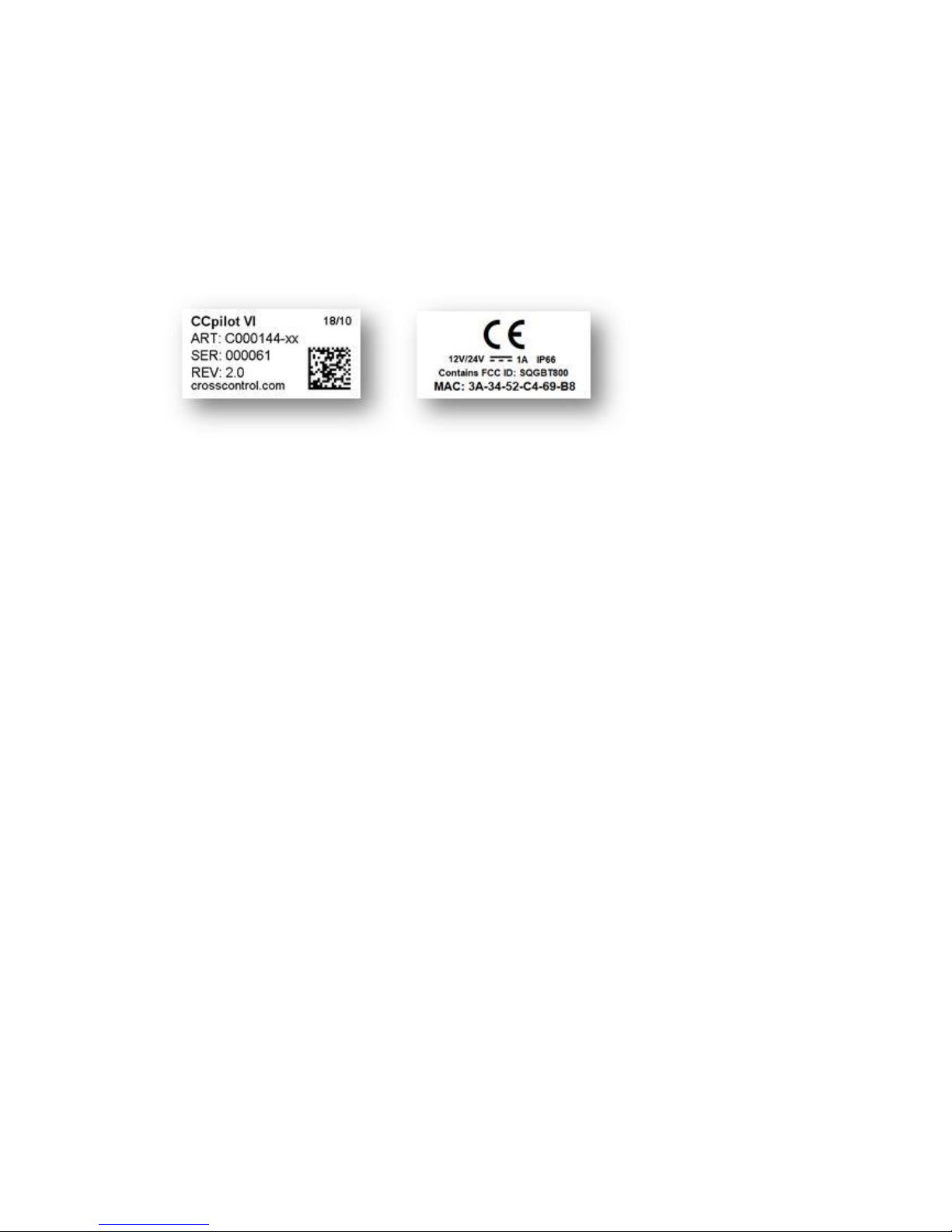
1.3. Identification............................................................................................................................... 5
1.4. Environmental resistance ......................................................................................................... 5
2. Product overview .........................................................................................................................5
2.1. Front side view............................................................................................................................ 5
2.2. Rear side view ............................................................................................................................ 6
3. Mounting and handling...............................................................................................................7
3.1. Mounting ..................................................................................................................................... 7
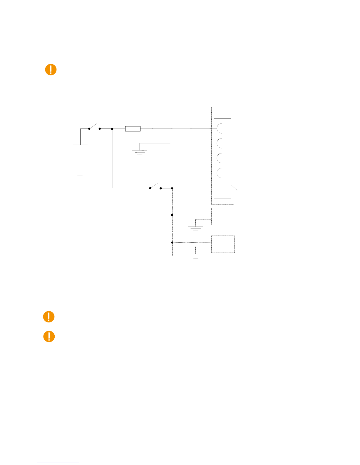
3.2. Connecting to power supply .................................................................................................. 9
3.3. Cable installation..................................................................................................................... 10
3.4. Special considerations............................................................................................................ 11
3.5. Handling and maintenance ................................................................................................. 12
3.6. Transportation........................................................................................................................... 13
4. Basic operation ..........................................................................................................................14
4.1. Turning ON ................................................................................................................................ 14
4.2. Turning OFF and suspending ................................................................................................. 14
4.3. Adjusting the screen brightness............................................................................................ 16
4.4. Status notification .................................................................................................................... 16
4.5. Error codes ................................................................................................................................ 17
5. Interface overview.....................................................................................................................18
5.1. Front panel................................................................................................................................ 18
5.2. Buzzer ......................................................................................................................................... 18
5.3. CAN............................................................................................................................................ 18
5.4. Ethernet ..................................................................................................................................... 18
5.5. USB .............................................................................................................................................. 19
5.6. Configurable inputs................................................................................................................. 19
5.7. Analog inputs ........................................................................................................................... 20
5.8. Low side outputs ...................................................................................................................... 20
5.9. Bluetooth ................................................................................................................................... 21
6. Connectors .................................................................................................................................22
6.1. Connector layout .................................................................................................................... 22
6.2. Deutsch DTM connectors, general ...................................................................................... 23
7. Specifications .............................................................................................................................24
7.1. Technical data......................................................................................................................... 24
7.2. Environmental specifications ................................................................................................ 27
7.3. EMC specification ................................................................................................................... 27
7.4. Weight and dimensions.......................................................................................................... 28
Technical support............................................................................................................................30
Trademarks and terms of use ........................................................................................................30
Index.................................................................................................................................................31

CCpilot VI
Revision: 2.0.0
Technical Manual
2018-10-19
www.crosscontrol.com
3
Revision history
Revision
Date
Issued by
Comments
2.0.0
2018-10-19
Lars Olsson

CCpilot VI
Revision: 2.0.0
Technical Manual
2018-10-19
www.crosscontrol.com
4
1. Introduction
CCpilot VI is a 3.5" full-colour display with Linux operating system. The open LinX software
platform offers a choice of powerful tools for application development. This, together with a QVGA
high brightness display and hardware accelerated 2D, 3D and vector graphics, enables fast design
of premium user interfaces.
With 4 freely configurable, backlit soft keys, operators can interact efficiently with the system.
CCpilot VI has multifunctional capability and can be used as instrumentation display, machine
control HMI, electronic manual and more.
This technical manual provides important information regarding the product’s hardware and its
basic usage. For software and operating system specifics, please see additional documentation.
1.1. Product models
This documentation is applicable for all CCpilot VI models. These models are:
CCpilot VI standard. COTS version of product. Part number C000144-05
CCpilot VI standard with Bluetooth module. Not available COTS. Part number:
C000144-02
CCpilot VI custom version with Bluetooth module and without I/O interfaces. Not
available COTS. Part number C000144-01.
These models share the same level of performance, hardware architecture, enclosure and
connectors. The PCB is the same for all versions but is populated differently.
1.2. Document conventions
This document uses the following conventions:
Description
Appearance
Important information
Differences between product
models
(exclamation symbol)
(observe’ symbol)
Text formats used in this document are described in the table below:
Format
Use
Italics
Names, designations, and references
Bolded
Important information

CCpilot VI
Revision: 2.0.0
Technical Manual
2018-10-19
www.crosscontrol.com
5
1.3. Identification
Each device has identification labels with serial number, part number and revision which identifies
your unique device. This information is required when communicating with CrossControl regarding
Technical support and Service/Repair needs.
Figure 1: Identification labels
1.4. Environmental resistance
The CCpilot VI product has been designed to manage tough environmental demands. Much effort
has been put into designing and selecting system components to provide a reliable and robust
device.
Thorough testing has been performed in order to ensure compliance to a broad range of applicable
regulatory requirements and to meet the user expectations of a ruggedized product for machinery
control.
A complete list of standards to which the product has been tested for compliance can be found in
chapters 7.2 and 7.3.
2. Product overview
This chapter contains illustrations of the CCpilot VI showing the location of external connectors,
indicators etc. Connectors are described in more detail in chapter 6. Additional mechanical
information can be found in chapter 7.4.
2.1. Front side view
The product has a 3.5” widescreen display protected by an anti-glare treated top glass. There are
also 4 freely configurable, backlit soft keys.

CCpilot VI
Revision: 2.0.0
Technical Manual
2018-10-19
www.crosscontrol.com
6
Figure 2: CCpilot VI front side view
2.2. Rear side view
The product has 2 connectors for external interfaces. Connectors are of type Deutsch DTM-12. On
the rear side you also find the buzzer sound outlet, a Gore-Tex ventilation membrane and
mounting holes for either a fastener in accordance with AMPS hole pattern (RAM 2.43” x 1.31”
Diamond Base) or a bracket for panel mounting.
Figure 3: CCpilot VI rear side view
Soft keys with user
configurable functionality.
Display with anti-glare
glass
GORE-TEX
membrane, under
mount for added
protection
Sound exit hole
under mount for
added protection
External connectors
Deutsch DTM
1
2
3
4
Soft key numbering.

CCpilot VI
Revision: 2.0.0
Technical Manual
2018-10-19
www.crosscontrol.com
7
3. Mounting and handling
This chapter contains recommendations for installation, handling and maintenance of the product.
3.1. Mounting
CCpilot VI supports two different mounting methods, a RAM mount or a panel mount. These two
mounting methods are described separately below.
For both fastening methods, use the appropriate M5 x 0.8 button head screw of type MRT (Torx)
The recommended torque for the screws is 1.5-2.0 Nm. Using fluid locker or locking washers (split
ring, toothed lock, etc.) is required for proper mounting. Ensure that the M5 mounting screws are
clean and dry before mounting.
Note that the depth of the threaded holes is 8 mm. Be careful not to use too long screws which may
damage the device when tightened.
3.1.1. RAM mount
CCpilot VI is preferably mounted using a RAM-B-238U Mount which allows adjustment of the
display’s position and angle. Screw length should be 12mm.
3.1.2. Panel mount
Panel mounting requires a bracket (P/N C000135-81) and a rubber frame(P/N C000144-44) see
pictures below. The mounting bracket is designed for min 1,5mm and max 3mm panel thickness.
Screw length should be 10mm.

CCpilot VI
Revision: 2.0.0
Technical Manual
2018-10-19
www.crosscontrol.com
8
Ensure that CCpilot VI is mounted to a smooth, flat surface. Fastening the unit to an uneven
surface may stress the enclosure, damage the outer flange or possibly even flex the circuit board
inside, leading to a premature failure.
Panel cut-out information available in dxf-format upon request for precision cutting of panels.

CCpilot VI
Revision: 2.0.0
Technical Manual
2018-10-19
www.crosscontrol.com
9
3.2. Connecting to power supply
This chapter describes how the CCpilot VI is preferably connected to the power supply of the
equipment it is installed in. The principle is the same for vehicular and stationary installations.
Carefully read through the following sub-chapters. They are critical for designing and adapting the
electrical system of the equipment in which the CCpilot VI is installed. Connector pinouts are found
in chapter 6.
3.2.1. Wire gauge
Wire gauge for the power supply should be dimensioned with respect to the current and voltage at
cranking.
Current consumption of the CCpilot VI device is found in chapter 7.1.
Power consumption of external loads driven by the CCpilot VI device should also be taken
into account.
The wire gauge for the power supply is recommended to be at least 0.75 mm2/AWG 18 for
“normal” loads.
The DTM connectors accept wire gauges between 0.75 and 3.3 mm2/AWG 12 to 18.
3.2.2. External fuse
To prevent cable fire in case of short circuit, an external fuse must always be used when powering
the device from a high current capable power source, for example a vehicle battery.
The fuse shall be located as close to the battery/power source as practically possible.
Fuse rating shall be dimensioned with respect to wire gauge, maximum current
consumption and the inrush current of the device. Refer to chapter 7.1 for fuse rating
details.
As a guideline, a slow acting fuse with 2-3 A current rating should be used.
Remember to also apply fusing for the on/off control wiring, see chapter 3.2.4.
3.2.3. External key switch signal
The device’s key switch signal should be connected to the positive supply line via the vehicle’s
ignition key switch.
The wire gauge for the key switch signal shall be dimensioned to handle the total switch
current and the fuse type and rating shall be selected to prevent cable fire in case of cabling
short circuit.
As a guideline, a slow acting fuse in the range of 100-1000 mA for the key switch signal
should be sufficient for most practically usable wire gauge.
3.2.4. Application example
Below is an application example schematic of the CCpilot VI power supply connection.
If the system has a main switch for completely disconnecting the battery (S1 in schematic below),
the device’s power supply and key switch signal shall be connected after the main switch.

CCpilot VI
Revision: 2.0.0
Technical Manual
2018-10-19
www.crosscontrol.com
10
It is not recommended to disconnect the battery without shutting down the device first - since
doing so will immediately switch off all internal voltages, regardless of ongoing operations. Any
information which was not saved to flash memory will be lost when disconnecting the battery.
However, no physical damage will be caused to the device by disconnecting the battery.
Figure 4: Schematic example for power supply installation of a CCpilot VI device in a
vehicle. The ignition switch (S2) can be shared by several devices (Device X, Y, …)
By connecting the power supply according to the example above, the CCpilot VI device will
automatically start up when the key switch (S2) is closed and shut down when the switch is opened.
Note that the on/off behavior of the CCpilot VI described here is the default configuration. Its
response to the on/off signal may be altered using the CCAux API, see chapter 4.1 for more details.
Be advised that the device consumes a small amount of power from the main supply also when
shutdown (55 µA at 12V, 0.31mA at 24V) or suspended (36mA at 12V, 20mA at 24V). Therefore, if
the device has been attached for a long period of time without the vehicle motor running, the
battery may be drained, resulting in inability to start up the vehicle. A main switch for
disconnecting the device’s main supply is highly recommended in such situations.
3.3. Cable installation
Cables shall be installed in such a way that they do not run any risk of being damaged, pinched or
worn.
Avoid excessive bending and twisting of cables.
Use strain-relief on cables near the device to minimize stress on cables and connectors.
GND
1
2
3
4
F1
2-3 A
GND
BATTERY
S2
(Turnkey
switch)
Multipin
connector 1
:
:
F2
0.1-0.5 A
Device B
GND
Device C
GND
IMAX: 2.5 mA
Min 0.75 mm2/AWG 18
S1
(Main switch)
(on/off control)
Min 0.75 mm2/AWG18
Device A

CCpilot VI
Revision: 2.0.0
Technical Manual
2018-10-19
www.crosscontrol.com
11
Properly snap the connectors to give reliable contact and sealing and to avoid unnecessary
strain.
Shielded cables are recommended and in some cases necessary to ensure reliable
communication and appliance with agricultural EMC standards.
3.3.1. Recommendations for cable shields
To achieve electromagnetic compliance and stable operation of the system, shielded cables are
required for Ethernet and USB interfaces.
When using shielded cables for Ethernet, the shield is preferably connected/grounded at the other
end of the cable (and remains unconnected close to the CCpilot VI device).
Below are recommendations for inserting cable shields and coaxial cables into Deutsch DTM plugs
to achieve robust connections and retaining IP classification of the device.
Splice the cable shield (or coaxial inner and outer conductors) outside of the DTM plug and
use regular, round cables for insertion into the plug.
Minimize distance between cable joints and the DTM plugs for best shielding effect.
3.4. Special considerations
To ensure proper and reliable operation and to retain IP-classification of the device, below
recommendations must be followed:
The device should be placed in a way that prevents direct and continuous exposure to water
or close proximity to hot-air vents.
To enable sufficient cooling, the device must be installed in a way that allows ambient air to
circulate around it. A clearance of at least 50 mm around the device is recommended.
To maintain IP classification, all Deutsch DTM connectors must have a mating external
connector attached. Blind connector plugs must be used if a connector does not have a
mating external connector. Please note that the protective caps mounted on the DTM
connectors are for transportation protection only.
The device has a ventilation membrane, refer to Figure 3 for the location. For proper
ventilation of the device, dirt and water must be prevented from accumulating and covering
the membrane. Be cautious not to insert objects which may puncture the membrane. Doing
so will violate the IP-classification and void the warranty of the device.
Install the device and any cables attached in a way that they are not subject to excess
vibrations or other potentially harmful stress.
Loose fasteners is a common cause for excessive vibration. Fasteners may come loose due
to improper mounting techniques such as omitting thread lockers (fluid locker or locking
washers) or by over/under-tightening. Proper tightening requires dry, clean fasteners and a
torque wrench.
If the device is exposed to chemicals, water, dirt or other pollutants, it is recommended to
have it cleaned off as soon as possible. See chapter 3.5.1 for cleaning instructions.

CCpilot VI
Revision: 2.0.0
Technical Manual
2018-10-19
www.crosscontrol.com
12
3.5. Handling and maintenance
Handle the device with care and pay attention to the following handling instructions:
Disconnect all cables to the device during welding or when performing other service to the
machine imposing a risk of damaging electronic devices.
Service and repair to the device shall only be made by authorized personnel. If the device is
opened by unauthorized personnel, its warranty will be void.
Scratches or other damages may occur to the display surface if it is exposed to sharp
objects, abrasives or heavy impacts. This must be avoided to increase the longevity of the
screen.
The internal eMMC flash storage has a limited number of write cycles. Therefore it is
recommended that the amount of writing to flash is limited within software applications.
1
Always consider personal safety when installing and operating the product. For example,
in vehicle installations, CrossControl does not recommend that the product is being
actively operated by the driver when a risk of injury to people or damage to property is
present.
3.5.1. Cleaning
To ensure proper and reliable functionality over time, pay attention to the following cleaning
instructions and precautions:
Wipe the device clean from dirt using a soft damp cloth, preferably of microfiber type.
Larger amount of dry dust may be swept off using a soft brush before wiping clean.
Avoid using alkaline, alcoholic or other potentially adverse chemicals for cleaning as doing
so may damage the device. However, small amount isopropyl alcohol may be used for
removing harsh stains.
Avoid spraying or by other means applying larger amount of water or alcohol directly to
the device. Instead, lightly dampen a cloth before using it for cleaning the device.
After cleaning, make sure that the device surface is left dry.
Never use high-pressure air, vacuum, water or steam to clean the device.
3.5.2. Real time clock battery
Time and date information is stored in a memory sustained by an internal back-up battery. The
battery is a 3V 1000mAh high operating temperature Poly-carbonmonofluoride Lithium battery.
The expected life time of the battery is approximately 20 years. The battery is not replaceable.
1
The eMMC is used in pseudo SLC mode and implements both static and dynamic wear levelling to reach the
best reliability. The number of program/erase cycles is between 20k to 60k depending on the manufacturer and
temperature. Our recommendation for the application software is to temporary cache in RAM and to write larger
chunks of data to the eMMC. This recommendation is not specific to eMMC but is applicable to all flash
memories.

CCpilot VI
Revision: 2.0.0
Technical Manual
2018-10-19
www.crosscontrol.com
13
3.6. Transportation
When transporting the device it is recommended to use the original packaging. Make sure that
protective caps are used on all non-mated connectors. The storage temperature interval [-30°C to
+80°C] must be met.

CCpilot VI
Revision: 2.0.0
Technical Manual
2018-10-19
www.crosscontrol.com
14
4. Basic operation
This section covers basic operation of the product such as start-up, shut-down, suspend, resume,
display operation and status notification.
Observe that the behaviour of on/off controls (external on/off control and soft keys) is user
configurable in terms of:
Enabling/disabling functionality
Which soft keys that shall hold the on/off functionality
Configurable timing parameters
External on/off control edge or level triggered
The soft keys present status notifications during start up by flashing the soft keys backlight or
beeping with the buzzer in different patterns.
The status notification behaviour in the operational state of the device is configurable by user
applications. Described herein are the factory default behaviours of the on/off controls and the
status notification.
4.1. Turning ON
The CCpilot VI product can be started up in different ways:
1. By connecting the external on/off control signal to positive supply input (or above
approximately 4V).
oWhen started this way, the on/off signal must remain asserted. De-assertion of this
signal will shut down the device unless configured otherwise.
2. By a short-press on the soft key configured for on/off control.
a. Note that this function is enabled on soft key 1 as factory default.
3. It is possible to configure the device to automatically start up whenever external power is
applied (i.e. without using any on/off control).
a. Note that this function is disabled as factory default.
For resuming the device from suspend mode, see chapter 4.2.
While starting up the device, it will give a short beep and the soft key backlight will flash with 2 Hz.
When the device enters operational state the soft key backlight will stop flashing and be turned on.
4.2. Turning OFF and suspending
There are several ways to turn off the CCpilot VI device and also alternatives to enter suspend mode
instead of completely shutting down the device.
4.2.1. Shutting Down
There are a number of ways to shut down the device, provided that it is in normal operational state
when the action occurs:
1. By disconnecting the external on/off control for more than a specified time, i.e. using the
turn-key functionality.

CCpilot VI
Revision: 2.0.0
Technical Manual
2018-10-19
www.crosscontrol.com
15
oThe time-out is user configurable and defaults to 4 seconds.
oIf the on/off signal is brought back high again while the device is shutting down, it
won’t restart automatically. A low-to-high transition must occur after the device
has fully shut down to make a restart.
2. By using the soft keys (action configurable for either short-press or long-press of the soft
key)
oThe time used for detecting long-presses is user configurable and defaults to 4
seconds.
oA prolonged long-press (more than 8 seconds) gives a forced shutdown where the
internal voltages are shut off immediately.
oBy factory default, a long press on soft key 1 triggers a shutdown event.
4. By operating system shutdown requests.
To ensure that data does not get lost or the flash memory becomes corrupt, it is recommended that
all necessary data shall be saved and all programs closed before the device is shut down.
Note that the device won’t shut down from Suspend mode by these actions. See chapter 4.2.2 for
details of Suspend mode and wakeup.
When performing any of the above, the CCpilot VI device will shut down. The soft key backlight will
flash and the device will beep to indicate that releasing the soft key configured for shutting down
will result in the device starting to shut down.
4.2.2. Suspending/resuming
Suspending and resuming are faster alternative to shutting down and starting up the device. In
suspend mode, the data remains in RAM memory and the device must be connected to external
power supply to maintain its state.
Suspend mode can be entered in a number of ways:
1. By disconnecting the external on/off control, i.e. using the turn key functionality.
oBy factory default, disconnecting the external on/off control is configured to shut-
down the device.
2. By using the soft keys (action configurable for either short-press or long-press of the soft
key)
oBy factory default, a short press on soft key 1 triggers a suspend event.
3. By selecting the operating systems suspend alternative.
Observe that the product current consumption in suspend mode is higher than in shut-down mode.
To prevent a vehicles or machines battery from draining when the device is suspended, a user
configurable time-out can be set for how long the unit shall stay in Suspend mode before it
automatically shuts down. The default Suspend time-out is set to 60 minutes.
Resuming from Suspend mode can be done by one of the following events:

CCpilot VI
Revision: 2.0.0
Technical Manual
2018-10-19
www.crosscontrol.com
16
1. By a low-to-high transition of the external on/off control, i.e. using the turn-key
functionality.
2. By pressing a soft key configured for resuming from suspend (configured as start-up
trigger).
oBy factory default, a short press on soft key 1 will wake up the device.
Configuration of how to wake up from suspend is done through the CCSettingsConsole application
or using the CCAux API. See the software guide for details.
4.2.3. Forced Shutdown
If the CCpilot VI is not responding, a forced shutdown can be performed by pressing and holding
soft keys 1 and 4 simultaneously until the device is switched off.
The soft key-press time for performing a forced shutdown is 10 seconds.
A forced shutdown immediately shuts down the device, regardless of its operational state. Any
information which was not saved will be lost when performing a forced shutdown. Any ongoing
writing to the flash memory will be disrupted which may lead to a corrupted file system.
Therefore it is not recommended to use the forced shutdown feature unless absolutely
necessary.
4.3. Adjusting the screen brightness
With the CCpilot VI product it is possible to configure soft keys as dedicated backlight brightness
soft keys to gradually increase or decrease the display brightness. By default, soft key 3 is
configured as backlight increase, and soft key 4 as backlight decrease.
The screen brightness can also be controlled from software.
4.4. Status notification
The soft keys present status notifications during start up and operational state by flashing the soft
keys backlight or beeping with the buzzer in different patterns.
The table below describes the default behaviour of the status notification for different operational
states. Note that the soft key backlight status notification can be configured to be turned off
completely.
Operational state
Soft key backlight behavior
Device off
Off
Starting up
Flashing, 2 Hz
Operating (started up)
Constant on
Shutting down
Flashing, 2 Hz
Suspended
Flashing 0.2 Hz
Entering forced shutdown
-After 8 seconds
Flashing 10 Hz for 3 seconds, then Off (device is
switched off)
Observe that the status notification behaviour in both the start-up and operating states is
configurable by user applications running on the device.

CCpilot VI
Revision: 2.0.0
Technical Manual
2018-10-19
www.crosscontrol.com
17
4.5. Error codes
The internal buzzer is used for signalling error codes when the device cannot start due to a
hardware failure. When this happens, the device will remain shut off, but indicates the failure
reason by beeping the buzzer in a special pattern. The pattern is a certain number of beeps followed
by a longer pause after which the sequence is repeated. The number of beeps is important
information if the device is sent in for service/repair. The table below lists the different error codes.
Number of
beeps
Error code
Likely problem cause
1
errCodeReadErrEEPROM
Corrupted configuration
settings in SS FRAM.
2
errCodeWriteErrEEPROM
Corrupted configuration
settings in SS FRAM.
3
errCodeDriverInit
SS FRAM or temp sensor
malfunction.
4
errCodeInternalVoltageOutOfLimits_NoBlinks
Internal voltages is outside
allowed limits.
5
errCodeMPDoneTimeoutErr
Faulty or unprogrammed
NAND Flash (OS image) or
hardware error.
6
errCodeTimeOutWaitingForVoltages
Unstable internal voltages.
7
errCodeTEMPOutOfLimits
Temperature sensor
malfunction or extreme
operating conditions.
10
errCodeRCCInit
SS clock crystal malfunction
or SS processor failure.
11
errCodeSSState
SS processor failure or
programming bug.
12
errCodeManageDiagnostics
Corrupted configuration
settings in SS FRAM.
13
errCodeManageActDeAct
SS processor failure or
programming bug.
14
errCodeTickTimeOutTimer
SS processor failure or
programming bug.
15
errCodeOperateModeStateError
SS processor failure or
programming bug.
16
errCodeHALIOReadErr
SS processor failure or
programming bug.
17
errCodeHALIOWriteErr
SS processor failure or
programming bug.

CCpilot VI
Revision: 2.0.0
Technical Manual
2018-10-19
www.crosscontrol.com
18
5. Interface overview
This section describes the various interfaces of the product. Main part of these interfaces can be
accessed via software APIs. These are described in the CCpilot VI Software Guide.
5.1. Front panel
5.1.1. Soft keys
CCpilot VI has four (4) software configurable soft keys. The soft keys may be used for user
application input, turning the unit on/off or controlling the backlight. Reference to the software
documentation for details on how configuration is done.
5.2. Buzzer
CCpilot VI has a built-in buzzer that can be used for audible notifications. The buzzer is software
controllable with configurable volume and frequency.
For buzzer location see Figure 3. See chapter 4.4 for buzzer notification events. Refer to the CCpilot
VI Software guide for details about controlling the buzzer from user applications.
5.3. CAN
CCpilot VI has one (1) CAN port that meets CAN ISO 11898 2.0B (29-bit extended identifier) and
supports bit rates up to 1 Mbps.
Note that Internal EMI filters on CAN High/Low signals have a capacitance of 100 pF (typ) which
deviates from the ISO 11898 standard and implies some limitations on the CAN bus topology
(maximum bus length, number of CAN nodes etc.) when running at high bit-rates, i.e. above 250
kbps.
The ports feature highly protected CAN transceivers which are tolerant for bus short-circuits to
main supply voltage and ground.
CAN shield connections are according to J1939-11 with capacitive coupling to ground. There is no
device-internal CAN bus termination, therefore bus termination must be applied externally.
5.4. Ethernet
CCpilot VI has one (1) Ethernet interface supporting 10BASE-T/100-BASE-TX and Auto-MDIX
with 500VAC/707VDC galvanic isolation.
Observe that:
The Ethernet interface has function isolation only and must be connected to other SELV
(Safety Extra Low Voltage) circuits only; i.e. local network without routing to outside plant.
Shielded cables shall be used for this port to ensure reliable communication and
electromagnetic compliance. The shield should be left unconnected on the Deutsch DTM-
12 connector i.e. CCpilot VI side of the Ethernet cable.
Connecting the device to a public network environment may impose a security threat.

CCpilot VI
Revision: 2.0.0
Technical Manual
2018-10-19
www.crosscontrol.com
19
5.5. USB
CCpilot VI has one (1) USB port. This port supports an USB OTG interface, i.e. acting as both host
and device. Using the port in USB device mode is only for OS updates through a connected PC with
appropriate tool installed.
In USB host mode, it can be used for application data transfer or the connection of a peripheral
such as a mouse or keyboard.
Due to the multipin connector specification, USB data signal integrity cannot be guaranteed with
higher speeds than full-speed USB (12 Mbps). However, hi-speed operation is supported by the
USB host controller.
The USB port can supply up to 500 mA. The USB port is internally over current and short circuit to
ground protected. Shielded cables shall be used to ensure reliable communication and
electromagnetic compliance. Depending on installation the shield could be connected to USB
ground or left unconnected on the Deutsch DTM-12 connector, i.e. CCpilot VI, side of the cable.
5.6. Configurable inputs
CCpilot VI has four (4) configurable inputs.
Each input can be configured for:
voltage measurement
frequency measurement
resistance measurement
digital input
oswitched to battery (internal pull-down)
oswitched to ground (internal pull-up)
The operating specifications for the various operating modes are provided below:
Mode
Range
Accuracy
Resolution
Voltage
5 V range: 0 V-5.5 VDC(typ) 5.3 V(min)
±0.5% ±5mV
1.4mV
Resistive
0-500 Ω
<1Ω, non
linear
<1Ω, non linear
Frequency
0.1-50000 Hz
100 ppm
time base
0.1 Hz up to 2.19 kHz,
1 Hz at 6.93 kHz,
2 Hz at 9.80 kHz,
4 Hz at 13.86 kHz,
52 Hz at 50.00 kHz.
(f2/48MHz)
Switched to
battery
11.1 kΩ pull-down
-
-
Switched to
ground
9.1 kΩ pull-up to internal 3.3V through
diode
-
-
Note that the input ground is internally joined with main supply ground. Precautions should be
made to avoid ground-loops between input ground and main supply ground. Ground-loop currents
may affect readings.

CCpilot VI
Revision: 2.0.0
Technical Manual
2018-10-19
www.crosscontrol.com
20
The co-processor handles the configurable input and adds features such as averaging for frequency
measurements. Measurement results are accessible to user applications through software APIs.
Refer to the CCAux API documentation for programming details. Each input mode is described
more in chapters 5.6.1 and 5.6.2 below.
5.6.1. Digital input and frequency measurement
Digital and frequency input modes can be used for connecting simple logical signals (for example
switch to battery/ground or various logic output sensors) or frequency-output sensors commonly
used in industrial applications.
The input can be set as either pull-down to ground or internal pull-up to 3V. This makes the input
compatible with a wide range of sensors with different output types.
Frequency measurement is implemented by timer captures at a time-base of 48 MHz (100 ppm).
This time-base gives a theoretical frequency resolution of approximately 0.02 Hz at 1 kHz and 4.7
Hz at 15 kHz (better resolution at lower frequencies). Refer to the CCAux API documentation for
details about available configurations.
See chapter 7.1 for electrical characteristics such as absolute maximum voltage, digital threshold
levels, pull-up strength, frequency range and accuracy.
5.6.2. Voltage measurement
The configurable inputs can be used for measuring DC-voltages in range of 0-5.3 V.
See chapter 7.1 for electrical characteristics such as impedance and accuracy.
5.6.3. Resistance measurement
The configurable inputs can be used for measuring resistive loads up to 500 Ω. The resistance
measurement mode bias the configurable input through an internal 124 Ωresistor connected to internal 3V for
measurement of the external resistance.
5.7. Analog inputs
CCpilot VI has three (3) fixed analog inputs with 0-5V range and 25 kΩ input impedance to ground.
5.8. Low side outputs
CCpilot VI has two (2) low side outputs. These two self-protected, low-side switched PWM outputs
have a maximum current rating of 1 A and can be used to control external loads such as a buzzer,
relay or indicator lamps. PWM duty cycle and frequency is adjustable via API/software.
Since the outputs are low sided, a duty cycle of 90% means 90% low, 10% high output.
For inductive loads it is important to have an external free-wheel diode at the load to protect the
output.
The low side outputs utilize Diodes Inc ZXMS6005N8 self-protected low side switch with the
following specification:
Continuous drain source voltage 60 V
On-state resistance 200 mΩ
Clamping energy 120 mJ
Short circuit protection with auto restart
Table of contents
Other crosscontrol Monitor manuals