crosscontrol CCpilot VS 12" User manual

Product revision: A
2017-11-23
CCpilot VS 12”
Technical Manual
www.crosscontrol.com

CCpilot VS 12”
Product revision: A
Technical Manual
2017-11-23
www.crosscontrol.com
2
Contents
Revision history ..................................................................................................................................3
1. Introduction ..................................................................................................................................4
1.1. Document conventions ........................................................................................................... 4
1.2. Identification............................................................................................................................... 4
1.3. Environmental resistance ......................................................................................................... 4
2. Device overview ..........................................................................................................................5
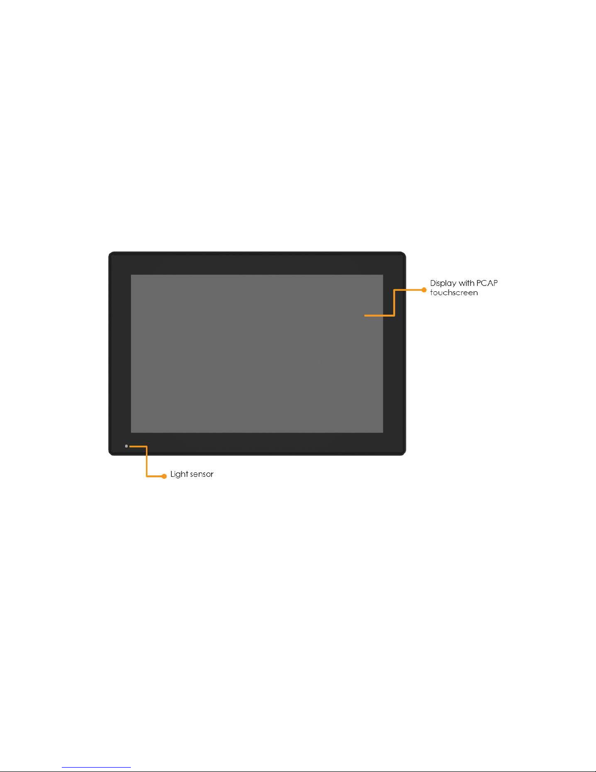
2.1. Front side view............................................................................................................................ 5
2.2. Rear side view ............................................................................................................................ 6
2.3. Left side view .............................................................................................................................. 6
3. Mounting and handling...............................................................................................................7
3.1. Mounting ..................................................................................................................................... 7
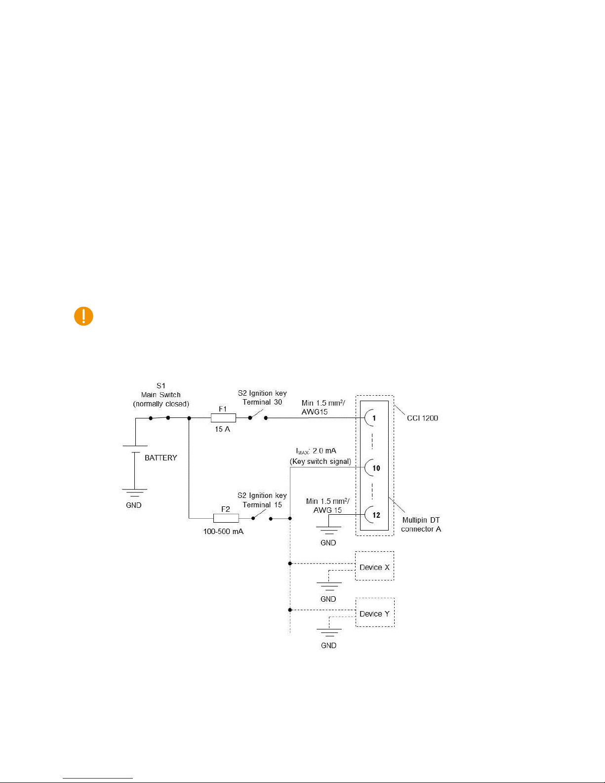
3.2. Connecting to power supply .................................................................................................. 7
3.3. Cable installation....................................................................................................................... 9
3.4. Special considerations.............................................................................................................. 9
3.5. Handling and maintenance ................................................................................................. 10
3.6. Transportation........................................................................................................................... 11
3.7. Decommissioning .................................................................................................................... 11
4. Basic operation ..........................................................................................................................11
4.1. Turning ON/OFF ........................................................................................................................ 11
4.2. Light sensor................................................................................................................................ 12
4.3. Using the touch screen........................................................................................................... 12
4.4. Status notification .................................................................................................................... 12
4.5. Error codes ................................................................................................................................ 13
5. Interface overview.....................................................................................................................14
5.1. Front panel................................................................................................................................ 14
5.2. Buzzer ......................................................................................................................................... 15
5.3. Analog video input ................................................................................................................. 15
5.4. CAN............................................................................................................................................ 15
5.5. Ethernet ..................................................................................................................................... 15
5.6. USB .............................................................................................................................................. 16
5.7. Analog input............................................................................................................................. 16
5.8. Configurable input .................................................................................................................. 16
5.9. High-side outputs ..................................................................................................................... 17
5.10. RS-232....................................................................................................................................... 18
5.11. RS-485....................................................................................................................................... 18
5.12. Key switch signal.................................................................................................................... 18
6. Connectors .................................................................................................................................18
6.1. Deutsch DT connectors, general.......................................................................................... 19
6.2. Deutsch DT connector A pinout ........................................................................................... 20
6.3. Deutsch DT connector B pinout............................................................................................ 20
6.4. Deutsch DT connector C pinout........................................................................................... 20
6.5. M12 connectors, general....................................................................................................... 21

CCpilot VS 12”
Product revision: A
Technical Manual
2017-11-23
www.crosscontrol.com
3
6.6. USB M12 connector pinout .................................................................................................... 21
6.7. Ethernet M12 pinout................................................................................................................ 21
6.8. USB Type A connectors, general .......................................................................................... 22
6.9. USB Type A pinout.................................................................................................................... 22
7. Specifications .............................................................................................................................22
7.1. Technical data......................................................................................................................... 22
7.2. Environmental specifications ................................................................................................ 26
7.3. EMC specification ................................................................................................................... 26
7.4. Weight and dimensions.......................................................................................................... 27
Technical support............................................................................................................................29
Trademarks and terms of use ........................................................................................................29
Index.................................................................................................................................................30
Revision history
Rev
Date
Author
Comments
A
2017-11-23
Released

CCpilot VS 12”
Product revision: A
Technical Manual
2017-11-23
www.crosscontrol.com
4
1. Introduction
CCpilot VS is a display computer with a 12” widescreen high-resolution TFT and PCAP touch
screen. The strong LED backlight in combination with the optically bonded PCAP, results in
excellent sunlight readability properties.
The powerful Arm® based main CPU and Linux® operating system constitute an open platform
that facilitates the implementation of premium user-machine interaction, reliable controls and
integrated fleet management solutions. In addition, there is one co-processor responsible for
hardware control and supervision.
This technical manual provides important information regarding the device’s hardware and its
basic usage. For software and operating system specifics, please see additional documentation.
1.1. Document conventions
This document uses the following conventions:
Description
Appearance
Important information
(exclamation symbol)
Text formats used in this document are described in the table below:
Format
Use
Italics
Names, designations, and references
Bolded
Important information
1.2. Identification
Each device has an identification label with serial number, article number and revision which
identify your unique device. Take note of these numbers. During service and other contact with the
supplier it is important to be able to provide this information.
Figure 1: Identification label
1.3. Environmental resistance
The CCpilot VS 12” device has been designed to manage tough environmental demands. Much
effort has been put into designing and selecting system components to provide a reliable and robust
device.
Thorough testing has been performed in order to ensure compliance to a broad range of applicable
regulatory requirements and to meet the user expectations of a ruggedized device for machinery
control.
A complete list of standards to which the device has been tested for compliance can be found in
chapters 7.2 and 7.3.

CCpilot VS 12”
Product revision: A
Technical Manual
2017-11-23
www.crosscontrol.com
5
2. Device overview
This chapter contains illustrations of the CCpilot VS 12” showing the location of external
connectors, indicators etc. Connectors are described in more detail in chapter 6. Additional
mechanical information can be found in chapter 7.4.
2.1. Front side view
At the front side of the device there is a 12” widescreen display with a projected capacitive touch-
sensor (PCAP).
There is a light sensor in the front panel which enables automatic dimming of display.
Figure 2: CCpilot VS front side view

CCpilot VS 12”
Product revision: A
Technical Manual
2017-11-23
www.crosscontrol.com
6
2.2. Rear side view
At the rear side of the device there are interface connectors, i.e. 3x Deutsch DT connectors, 2x M12
USB connectors and a M12 Ethernet connector.
There are also four M5 threaded inserts for mounting the device to a VESA75 mount.
Finally, there is a combined sound exit hole and ventilation membrane.
Figure 3: CCpilot VS rear side view
2.3. Left side view
On the left side of the device there is an on/off button with a built-in RGB status LED as well as two
USB type A connectors, placed under dust-protecting lids.
Figure 4: CCpilot VS left side view

CCpilot VS 12”
Product revision: A
Technical Manual
2017-11-23
www.crosscontrol.com
7
3. Mounting and handling
This chapter contains recommendations for installation, handling and maintenance of the device.
3.1. Mounting
CCpilot VS 12” supports a standardized VESA75 mounting interface.
It is recommended to use 4 pc. M5 x 0.8 Allen screws, with a length of 12 mm. The recommended
fastening torque is 1.5 - 2.0 Nm. Using fluid locker or locking washers (split ring, toothed lock, etc.)
is required for proper mounting. Ensure that the M5 mounting screws are clean and dry before
mounting.
Note that the depth of the threaded holes is 8 mm. Be careful not to use too long screws which may
damage the device when tightened.
3.2. Connecting to power supply
This chapter describes how the CCpilot VS is preferably connected to the power supply of the
vehicle. The principle is the same also for other types of installations.
Carefully read through the following sub-chapters before installing the device. Connector pinouts
are found in chapter 6.
3.2.1. Wire gauge
Wire gauge for the power supply should be dimensioned with respect to the start current at
cranking.
Current consumption of the CCpilot VS 12” device is found in chapter 7.1.
Power consumption of external loads driven by the CCpilot VS 12” device should also be
taken into account.
The wire gauge for the power supply is recommended to be at least 1.5 mm2/AWG 15 for
“normal” loads and at least 2.5 mm2/AWG 14 if using high external loads.
The DT connectors accept wire gauges between 0.75 and 3.3 mm2/AWG 12 to 18.
3.2.2. External fuse
To prevent cable fire in case of short circuit, an external fuse must always be used when powering
the device from a high current capable power source, for example a vehicle battery.
The fuse shall be located as close to the battery/power source as practically possible.
Fuse rating shall be dimensioned with respect to wire gauge, maximum current
consumption and the inrush current of the device. Refer to chapter 7.1 for fuse rating
details.
As a guideline, a slow acting fuse with 15 A current rating should be used.
Remember to also apply fusing for the on/off control wiring, see chapter 3.2.4.

CCpilot VS 12”
Product revision: A
Technical Manual
2017-11-23
www.crosscontrol.com
8
3.2.3. External key switch signal
The device’s key switch signal should be connected to the positive supply line via the vehicle’s
ignition key switch.
The wire gauge for the key switch signal shall be dimensioned to handle the total switch
current and the fuse type and rating shall be selected to prevent cable fire in case of cabling
short circuit.
As a guideline, a slow acting fuse in the range of 100-500 mA for the key switch signal
should be sufficient for most practically usable wire gauge.
3.2.4. Application example
Below is an application example schematic of the CCpilot VS 12” power supply connection.
If the system has a main switch for completely disconnecting the battery (S1 in schematic below),
the device’s power supply and key switch signal shall be connected after the main switch.
It is not recommended to disconnect the battery without shutting down the device first - since
doing so will immediately switch off all internal voltages, regardless of ongoing operations. Any
information which was not saved to flash memory will be lost when disconnecting the battery.
However, no physical damage will be caused to the device by disconnecting the battery.
Figure 5: Schematic example for power supply installation of a CCpilot VS 12” device in a
vehicle. The ignition switch (S2) can be shared by several devices (Device X, Y, …)
By connecting the power supply according to the example above, the CCpilot VS 12” device will
automatically start up when the key switch (S2) is closed and shut down when the switch is opened.

CCpilot VS 12”
Product revision: A
Technical Manual
2017-11-23
www.crosscontrol.com
9
Note that the on/off behavior of the CCpilot VS 12” described here is the default configuration. Its
response to the on/off signal may be altered using the CCAux API, see chapter 4.1 for more details.
3.3. Cable installation
Cables shall be installed in such a way that they don’t run any risk of being damaged, pinched or
worn.
Avoid excessive bending and twisting of cables.
Use strain-relief on cables near the device to minimize stress on cables and connectors.
Properly snap the connectors to give reliable contact and sealing and to avoid unnecessary
strain.
Shielded cables are recommended and in some cases necessary to ensure reliable
communication and appliance with agricultural EMC standards.
3.3.1. Recommendations for cable shields and coaxial cables
To achieve electromagnetic compliance and stable operation of the system, shielded cables are
required for Ethernet and USB interfaces. In addition, it is recommended to use 75 Ω coaxial cables
for connecting analog video sources to the device.
When using shielded cables for Ethernet, the shield is preferably connected/grounded at the other
end of the cable (and remain unconnected close to the CCpilot VS 12” device).
When using shielded cables for the M12 USB ports, the shield is preferably spliced and joined with
the USB connector’s shield. Avoid creating ground-loops in the USB cable by insulating any
attached USB-devices from ground structures connected with the CCpilot VS 12” device.
Below are recommendations for inserting cable shields and coaxial cables into Deutsch DT plugs to
achieve robust connections and retaining IP classification of the device.
Splice the cable shield (or coaxial inner and outer conductors) outside of the DT plug and
use regular, round cables for insertion into the plug.
Minimize distance between cable joints and the DT plugs for best shielding effect.
3.4. Special considerations
To ensure proper and reliable operation and to retain IP-classification of the device, below
recommendations must be followed:
The device should be placed in a way that prevents direct exposure to water or close
proximity to hot-air vents.
To enable sufficient cooling, the device must be installed in a way that allows ambient air to
circulate around it. A clearance of at least 50 mm around the device is recommended.
To maintain IP classification, all three Deutsch DT connectors must be attached to the
device. Blind plugs must be used for unconnected pins. Please note that the protective caps
mounted on the DT connectors are for transportation protection only. The rubber sealing
of the USB-ports on the left side of the device must also be properly attached when not
using the USB-ports.

CCpilot VS 12”
Product revision: A
Technical Manual
2017-11-23
www.crosscontrol.com
10
The device has a ventilation membrane, refer to Figure 3 for the location. For proper
ventilation of the device, dirt and water must be prevented from accumulating and covering
the membrane. Be cautious not to insert objects which may puncture the membrane. Doing
so will violate the IP-classification and void the warranty of the device.
Install the device and any cables attached such that they are not subject to excess vibrations
or other potentially harmful stress.
Loose fasteners are a common cause for excessive vibration. Fasteners may come loose due
to improper mounting techniques such as omitting thread lockers (fluid locker or locking
washers) or by over/under-tightening. Proper tightening requires dry, clean fasteners and a
torque wrench.
If the device is exposed to chemicals, water, dirt or other pollutants, it’s recommended to
have it cleaned off as soon as possible. See chapter 3.5.1 for cleaning instructions.
3.5. Handling and maintenance
Handle the device with care and pay attention to the following handling instructions:
Disconnect all cables to the device during welding or when performing other service to the
machine imposing a risk of damaging electronic devices.
Service and repair to the device shall only be made by authorized personnel. If the device is
opened by unauthorized personnel, its warranty will be void.
Scratches or other damages may occur to the display surface if it is exposed to sharp
objects, abrasives or heavy impacts. This must be avoided to increase the longevity of the
screen.
The internal eMMC flash storage has a limited number of write cycles. Therefore it is
recommended that the amount of writing to flash is limited within software applications.
1
Always consider personal safety when installing and operating the device. For example, in
vehicle installations, CrossControl does not recommend that the device is being actively
operated by the driver when a risk of injury to people or damage to property is present.
3.5.1. Cleaning
To ensure proper and reliable functionality over time, pay attention to the following cleaning
instructions and precautions:
Wipe the device clean from dirt using a soft damp cloth, preferably of microfiber type.
Larger amount of dry dust may be swept off using a soft brush before wiping clean.
Avoid using alkaline, alcoholic or other potentially adverse chemicals for cleaning as doing
so may damage the device. However, small amount isopropyl alcohol may be used for
removing harsh stains.
Avoid spraying or by other means applying larger amount of water or alcohol directly to
the device. Instead, lightly dampen a cloth before using it for cleaning the device.
1
The eMMC is used in pseudo SLC mode and implements both static and dynamic wear levelling to reach the
best reliability. The number of program/erase cycles is between 20k to 60k depending on the manufacturer and
temperature. Our recommendation for the application software is to temporary cache in RAM and to write larger
chunks of data to the eMMC. This recommendation is not specific to eMMC but is applicable to all flash
memories.

CCpilot VS 12”
Product revision: A
Technical Manual
2017-11-23
www.crosscontrol.com
11
After cleaning, make sure that the device surface is left dry.
Never use high-pressure air, vacuum, water or steam to clean the device.
3.5.2. Real time clock battery
Time and date information is stored in a memory sustained by an internal back-up battery.
The expected life time of the battery is approximately 20 years. The battery is not replaceable.
3.6. Transportation
When transporting the device it is recommended to use the original packaging. Make sure that
protective caps are used on all non-mated connectors. The storage temperature interval [-30°C to
+80°C] must be met.
3.7. Decommissioning
When the device has reached its end of life it should be handed over to the supplier or other
qualified party for recycling the product in an environmentally friendly manner. The manufacturer
does not handle decommissioning of the product.
4. Basic operation
This section covers basic operation of the device such as start-up, shut-down, display operation and
status notification.
Observe that the behavior of the on/off controls (on/off button and key switch signal) is user
configurable.
Button backlight is used for status notification while starting up, shutting down or when the device
is in rescue mode. Both button backlight and the buzzer is software controllable for notifications
from user applications.
See chapter 4.4 for details of button backlight status notification.
The buzzer is used for audible alerts as well as for various error notifications, see chapter 4.5 for
error code details.
4.1. Turning ON/OFF
The device can be turned ON or OFF from different actions as described in the following chapters.
To avoid data loss or corrupted flash memory, it is recommended that necessary data is saved and
user applications are properly closed before the device is shut down.
4.1.1. Key switch signal
The factory default way of turning the device ON or OFF is by the use of the vehicle’s ignition
switch.
Turning the vehicle’s ignition key to position ON will start the device.

CCpilot VS 12”
Product revision: A
Technical Manual
2017-11-23
www.crosscontrol.com
12
Turning the vehicle’s ignition key to position OFF will turn off the device.
4.1.2. On/off button
While in off-state, pressing and holding the on/off button will turn ON the device.
While the device is operating, pressing and holding the on/off button for 1 sec will turn OFF the
device.
4.1.3. Linux shutdown command
The device can be turned OFF by executing Linux shell shutdown commands, for example:
# s h u t d o w n
4.1.4. Forced shutdown
If the device stops responding, a forced shutdown can be performed by pressing and holding the
on/off button until the device is switched off.
The button press response time for the forced shutdown (long press) is user configurable
and the default value is set to 8 seconds.
It is not recommended to use the forced shut down unless absolutely necessary - since doing so will
immediately switch off all internal voltages, regardless of ongoing operations. Any information
which was not saved to flash memory will be lost when performing a forced shutdown. However, no
physical damage will be caused to the device by a forced shutdown.
4.2. Light sensor
The CCpilot VS 12” contains a light sensor that can be used to automatically adjust the display
brightness, depending on the ambient light conditions. As depicted in Figure 2, the light sensor is
located in the lower left corner of the front surface. When automated dimming is enabled, the level
of sensitivity can be adjusted.
The screen brightness can also be manually controlled directly from user applications through
APIs.
For proper operation it is important to keep the light sensor opening clean and with free visibility.
4.3. Using the touch screen
To reduce the amount of reflections when operating under sunny conditions, the touch screen’s
protective glass is covered with an anti-glare film. Do not use any sharp or abrasive objects when
interacting with the touch screen.
Basic usage of the capacitive touch screen should be intuitive for most users. Note that the touch
screen is capable of handling two simultaneous touches.
4.4. Status notification
The LED in the on/off button is used for status notification while starting up, shutting down or in
other operational states. The buzzer may also be used for user notifications. See Table 1 for a
description of the status notification behavior for different operational states.

CCpilot VS 12”
Product revision: A
Technical Manual
2017-11-23
www.crosscontrol.com
13
Table 1: LED and buzzer indication for different operational states
Operational state
LED indication
Buzzer notification
Device off
OFF
-
Power applied, device off
OFF
-
Starting up
Yellow flashing, 2 Hz
Short beep
Operating (started up)
Static green
-
Shutting down
Static green
-
Forced shutdown
Blue flashing, 2 Hz
short beep
Rescue mode, starting
Static orange
Short beep
Rescue mode, running
Green flashing, 2 Hz
Software upgrade
Yellow flashing, 0.5 Hz
-
4.5. Error codes
The LED in the on/off button is also used for indicating error codes by emitting a blue blinking
pattern after shutdown of the device. The device may be started again when in this mode, by the
button or the key switch signal. Depending on the nature of the error, the device may start or go
back into error indication.
When an error occurs, the device is immediately shut down and the error is reported by blinking a
specific number of times corresponding to an error code (see table of error codes). The blinks will
be in a continuous sequence of 1 Hz blinks, with a longer pause of two seconds after the specific
number of blinks, allowing the end user to count the number of blinks. Refer to Figure 1 below for
an example.
Figure 6: Example of the blinking pattern for error code 3
When an error occurs, an error code is also immediately saved to persistent storage (FRAM). If
several errors occur before the device it is shut down, only the code of the first error is saved and
reported. The error code in persistent storage can be read and cleared from a user application.
Refer to Table 2: CCpilot VS 12” error codes for a complete listing of the error codes.
The number of blinks is important information if the unit is sent in for service/repair.
Table 2: CCpilot VS 12” error codes
Error code
Error code name
Likely problem cause
1
errCodeReadErrEEPROM
Corrupted FRAM. Invalid values. FRAM
may need to be manually
reprogrammed or replaced.
2
errCodeWriteErrEEPROM
Corrupted FRAM. Invalid values. FRAM
may need to be manually
reprogrammed or replaced.
3
errCodeDriverInit
FRAM or light sensor malfunction.
Problem with cable to button/USB PCB.
4
-
-
5
errCodeMPDoneTimeoutErr
Timeout waiting for the MP_DONE
signal –MP error. Boot loader missing.
Faulty or unprogrammed eMMC.
6
errCodeTimeOutWaitingForVoltages
Internal or external voltages did not
stabilize during start-up. Power supply

CCpilot VS 12”
Product revision: A
Technical Manual
2017-11-23
www.crosscontrol.com
14
current limitation. Power cables not
thick enough (>1.5 mm2).
7
errCodeTEMPOutOfLimits
Internal PCB temperature above 95 °C
or temperature sensor malfunction
8
-
-
9
-
-
10
errCodeRCCInit
SS circuit malfunction (clocks).
11
errCodeSSState
Programming bug or faulty processor.
12
errCodeManageDiagnostics
Failed to save diagnostic data to
FRAM.
13
errCodeManageActDeAct
HAL_IO errors (SS internal).
14
errCodeTickTimeOutTimer
HAL_IO errors (SS internal).
15
errCodeOperateModeStateError
SS internal.
16
errCodeHALIOReadErr
HAL_IO errors (SS internal).
17
errCodeHALIOWriteErr
HAL_IO errors (SS internal).
18
-
19
-
20
-
21
-
22
-
23
-
24
-
25
errCode12VOutOfLimits
Internal 12V voltage out of limits during
operation.
26
errCode5VOutOfLimits
Internal 5V voltage out of limits during
operation.
27
errCode3V3AOutOfLimits
Internal 3V3A voltage out of limits
during operation.
5. Interface overview
This section describes the various interfaces of the device. Main part of these interfaces can be
accessed via software APIs. These are described in the CCpilot VS 12” Software Guide.
5.1. Front panel
5.1.1. Touch screen
The front panel contains a projective capacitive (PCAP) touch screen, which is capable of handling
two simultaneous touches.
5.1.2. Light sensor
There is a light sensor in the front panel used by user applications or used with the built in
automated function for dimming of the display brightness.
For light sensor location, see Figure 2. Refer to the CCpilot VS 12” Software guide for details about
accessing the light sensor data from user applications.

CCpilot VS 12”
Product revision: A
Technical Manual
2017-11-23
www.crosscontrol.com
15
5.2. Buzzer
There is a built-in buzzer that can be used for audible notifications. The buzzer is software
controllable with configurable volume and frequency.
For buzzer location see Figure 3. See chapter 4.4 for buzzer notification events. Refer to the CCpilot
VS 12” Software guide for details about controlling the buzzer from user applications.
5.3. Analog video input
There is a video input for connecting an analog video source such as a rear-view camera. Displaying
of analog video is handled in hardware with minimum impact on CPU load.
The analog video input supports a wide range of commonly used composite video formats (both
PAL and NTSC).
See chapter 7.1 for details.
For proper video performance and to ensure electromagnetic compatibility, 75 Ω coaxial cable shall
be used for connecting the video source. Preferably use coaxial cables of type M17/94-RG179. Refer
to chapter 3.3.1 for recommendations about connecting video coaxial cable.
It is important to supply the analog video source with a stable well-filtered supply voltage. Note
that video input grounds are internally connected with main supply ground. Precautions should be
made to avoid ground-loops between the video source and main supply ground which could affect
video quality. One way of avoiding ground-loop is to add video isolators or use a video source with
galvanic isolation between supply and signal ground.
5.4. CAN
CCpilot VS 12” has four CAN ports, supporting ISO 11898 CAN 2.0B protocol (29-bit extended
identifier) and bit rates up to 1 Mbps.
CCpilot VS 12" is compliant with AEF ISO 11783.
Note that Internal EMI filters on CAN High/Low signals have a capacitance of 100 pF (typ) which
deviates from the ISO 11898 standard and implies some limitations on the CAN bus topology
(maximum bus length, number of CAN nodes etc.) when running at high bit-rates, i.e. above 250
kbps.
The ports feature highly protected CAN transceivers which are tolerant for bus short-circuits to
main supply voltage and ground.
CAN shield connections are according to J1939-11 with capacitive coupling to ground. There is no
device-internal CAN bus termination, therefore bus termination must be applied externally.
5.5. Ethernet
CCpilot VS 12” has an Ethernet interface supporting 10BASE-T/100-BASE-TX/1000-BASE-T and
Auto-MDIX.
The Ethernet interface is galvanic isolated with 1.0 kVAC insulation voltage.
Shielded cables shall be used to ensure reliable communication and electromagnetic compliance.
As with all Ethernet enabled devices, connecting the device to a public network environment may
impose an IT security threat.

CCpilot VS 12”
Product revision: A
Technical Manual
2017-11-23
www.crosscontrol.com
16
5.6. USB
CCpilot VS 12” has in total four USB ports; two ports are located in the M12 connectors 3 and 4 at
the rear of the device, and two ports are located in the USB type A connectors on the left side, refer
to Figure 3 and Figure 4 for localization of the ports. They can be used for connecting USB storage
devices or other peripherals such as mouse, keyboard or various wireless interfaces. All USB-ports
are capable of both full-speed (12 Mbps) and hi-speed (480 Mbps) communication.
Note that the sealing property (IP classification) of the device is not retained when removing the
protective rubber lids for accessing the USB ports on the left side.
Each USB ports can supply up to 2A. The USB ports are internally over-current and short-circuit to
ground protected.
Shielded cables shall be used to ensure reliable communication and electromagnetic compliance.
Refer to chapter 3.3.1 for recommendations about connecting shield cables.
5.7. Analog input
CCpilot VS 12” has one fixed analog input 0-14V range with 12.7 kΩ input impedance to ground.
5.8. Configurable input
CCpilot VS 12” has one configurable input for a wide range of digital and analog measurements.
This input can be configured according to Table 3 below.
Table 3: Input configurations
Input modes
Configurations
Digital input modes
Digital input
Range
0-10V
Input configurations
Pull-down (ca 14 kΩ to GND)
Pull-up (ca 4,7 kΩ to Vin and 14 kΩ to
GND)
Input modes
Mode 1
low level ca 2,5 V
High level ca 3,4 V
Mode 2
low level ca 1,5 V
High level ca 6,3 V
Frequency measurement
Range
0.1-10 000 Hz
Input configurations
Pull-down (ca 14 kΩ to GND)
Pull-up (ca 4,7 kΩ to Vin and 14 kΩ to
GND)
Input modes
Mode 1
low level ca 2,5 V
High level ca 3,4 V
Mode 2
low level ca 1,5 V
High level ca 6,3 V
Analog input modes
Voltage measurement
Range
0-32V
For electrical specification at different input modes, see chapter 7.1.
Note that the input ground is internally joined with main supply ground. Precautions should be
made to avoid ground-loops between input ground and main supply ground. Ground-loop currents
may affect readings.

CCpilot VS 12”
Product revision: A
Technical Manual
2017-11-23
www.crosscontrol.com
17
The co-processor handles the configurable input and adds features such as averaging for frequency
measurements. Measurement results are accessible to user applications through software APIs.
Refer to the CCAux API documentation for programming details. Each input mode is described
more in chapters 5.8.1 and 5.8.2 below.
5.8.1. Digital input and frequency measurement
Digital and frequency input modes can be used for connecting simple logical signals (for example
switch to battery/ground or various logic output sensors) or frequency-output sensors commonly
used in industrial applications.
The input can be configured for two different logic signal levels thresholds and can be set as either
pull-down only or internal pull-up (together with the pull-down). This makes the input compatible
with a wide range of sensors with different output types and signal levels.
The selectable internal pull-up is sourced from the main supply input through internal over-voltage
protection. Therefore, pull-up will follow the main supply voltage but never exceed 55 VDC in case of
main voltage transients.
Frequency measurement is implemented by timer captures at a time-base of 72 MHz (100 ppm).
This time-base gives a theoretical frequency resolution of approximately 0.014 Hz at 1 kHz and 3.12
Hz at 15 kHz (better resolution at lower frequencies). Refer to the CCAux API documentation for
details about available configurations.
See chapter 7.1 for electrical characteristics such as absolute maximum voltage, digital threshold
levels, pull-up strength, frequency range and accuracy.
5.8.2. Voltage measurement
The input can be used for measuring DC-voltages in range of 0-32 V.
See chapter 7.1 for electrical characteristics such as impedance and accuracy.
5.9. High-side outputs
CCpilot VS 12” has six self-protected high-side digital outputs for switching various external loads
such as buzzers, relays, solenoids, lamps or other resistive or inductive loads.
The high-side output drivers are powered from the main supply voltage through internal over-
voltage protection that limits the output voltage to 50 VDC (typ) in case of supply voltage transients.
Four of the outputs are specified for 400mA load and two are specified for 800mA load, but all use
the same technical solution. Each output is current-limited to 1200 mA per channel (typ).
Each output provides diagnostics/fault-detection for both ON- and OFF-state according to Table 4
below.
Table 4: Diagnostics and fault detection for high-side outputs
OFF-state
ON-state
Open load
-
Short to battery
-
-
Overload or short to ground
-
Over-temperature

CCpilot VS 12”
Product revision: A
Technical Manual
2017-11-23
www.crosscontrol.com
18
To ensure long-term reliability, the fault-detection flags are continuously monitored and each
output is automatically switched OFF in case its fault flag is triggered in ON state. An output
switched OFF by a fault condition must be re-enabled by the user or user application.
Observe that high continuous load of the outputs generates internal heat in the device. At high
ambient temperatures, this may lead to outputs automatically switching off because of thermal
protection. Outputs can be re-enabled by the user (or user application) once the driver IC
temperature has decreased below its threshold. If output over-temperature shutdown occurs, it is
recommended to improve air ventilation around the device and if possible reduce the amount of
output load.
Output on/off control as well as fault monitoring is handled by a co-processor and controlled
through CCAux API.
See chapter 7.1 for electrical characteristics such as channel resistance, timing, current limit, and
fault-detection details.
5.10. RS-232
CCpilot VS 12” has two RS-232 ports, each supporting communication rates up to 115200 bps.
See chapter 7.1 for electrical characteristics such as protection voltages.
5.11. RS-485
CCpilot VS 12” has one RS-485 port, supporting communication rates up to 9600 bps.
The RS-485 configuration in CCpilot VS 12” comprises one A/B pair, i.e. full-duplex
communication is not supported.
See chapter 7.1 for electrical characteristics such as protection voltages.
5.12. Key switch signal
To simplify the cable harness design, CCpilot VS 12” has two input pins reserved for the key switch
signal. These pins are connected internally, i.e. any of the pins can be used. Refer to chapter 6.2 and
6.3 for pinout details.
6. Connectors
All external connectors are accessible from the rear or left side of the device.
The main connectors are the three 12-pin Deutsch DT series connectors, marked with letters A, B
and C and features keying (A-, B- and C-key respectively). The DT connectors are located to the left
of the rear side. To the right of the rear side there are three M12 connectors, marked with 3, 4 and
Eth. Finally, on the left side of the device there are two USB type A connectors marked 1 and 2.
These USB connectors are protected under a rubber sealing. Refer to Figure 7 for an overview of the
connectors.

CCpilot VS 12”
Product revision: A
Technical Manual
2017-11-23
www.crosscontrol.com
19
Figure 7: CCpilot VS 12” connectors
Connector pinouts are found in the following chapters.
6.1. Deutsch DT connectors, general
Use caution and avoid plugging/unplugging Deutsch DT connectors while the device is powered up.
If a connector pin becomes bent the interface may not function correctly and the device should be
returned to the manufacturer for repair.
Pay close attention to the coding; violence or excessive force should not be used when mating the
connectors.
Note that the pin-order 1-12 in tables below are oriented as when looking at the receptacles from
the rear of the CCpilot VS 12” device, i.e. pin 1 at top-left position and pin 12 at bottom-left position,
see Figure 8.
Figure 8: DT connector pinout
The connector pins are rated for 13 A continuous current.
The DT connector pins are made of tin-plated brass. It is recommended to use tin-plated
receptacles in the mating connectors. Using different plating in the cable connectors might cause
galvanic corrosion.
Note that all three Deutsch DT connectors must be mated with its corresponding cable connector or
a proper blind plug to maintain the IP-classification.

CCpilot VS 12”
Product revision: A
Technical Manual
2017-11-23
www.crosscontrol.com
20
6.2. Deutsch DT connector A pinout
Table 5: DT connector A pinout
DT Connector A
Matching plug: DT06-12SA (A-key)
Pin
Signal
Comment
1
Power supply
12 V or 24 V, see chapter 3.2.4 for information on
connection
2
High side output 1
(max 800 mA load)
3
High side output 2
(max 400 mA load)
4
CAN1 high
5
CAN1 low
6
CAN1 ground
7
CAN2 high
8
CAN2 low
9
CAN2 ground
10
Key switch signal
See chapter 3.2.4 for information on connection
11
Not connected
12
Ground
6.3. Deutsch DT connector B pinout
Table 6: DT connector B pinout
DT Connector B
Matching plug: DT06-12SB (B-key)
Pin
Signal
Comment
1
High side output 3
(max 800 mA load)
2
CAN3 high
3
CAN3 low
4
CAN3 ground
5
CAN4 ground
6
Analog input
7
Key switch signal
See chapter 3.2.4 for information on connection
8
Ground
9
Configurable input
10
CAN4 high
11
CAN4 low
12
Ground
6.4. Deutsch DT connector C pinout
Table 7: DT connector C pinout
DT Connector C
Matching plug: DT06-12SC (C-key)
Pin
Signal
Comment
1
High side output 4
Video supply (max 400 mA load)
2
Video IN
3
Video shield
Internally connected to supply ground
4
RS-485B
5
RS-485A
6
High side output 5
(max 400 mA load)
7
Spare
8
Spare
9
High side output 6
RS-232 supply (max 400 mA load)
Other manuals for CCpilot VS 12"
2
Table of contents
Other crosscontrol Monitor manuals