Crosswinds Aviation DA20 C1 Eclipse Installation guide

Copyright © 2019 by Midwest Air LLC
DA20 C1 Eclipse
Training Manual

Copyright © 2019 by Midwest Air LLC
Contents
1Aircraft Systems 3
1.1 Engine 3
1.2 Oil 3
1.3 Propeller 4
1.4 Landing Gear 4
1.5 Brakes 4
1.6 Flaps 4
1.7 Pitot Static System 4
1.8 Stall Warning Horn 4
1.9 Fuel System 5
1.10 Electrical System 6
1.11 Ignition System 6
1.12 Garmin G500 System 6
2Performance, Weight & Balance 8
2.1 V-speeds 8
2.2 Weight & Balance 8
3DA20 Procedures guide 9
3.1 Passenger Briefing 9
3.2 Flight Instrument Check 9
3.3 Flight instrument Check During Taxi 9
3.4 Pre-Takeoff Briefing 9
4Takeoff Procedures 11
4.1 Normal Takeoff (Flaps T/O) 11
4.2 Short Field Takeoff (Flaps T/O) 12
4.3 Soft Field Takeoff (Flaps T/O) 13
5Landing Procedures 14
5.1 VFR Landing Briefing Procedure 14
5.2 Before Landing Checklist 14
5.3 Normal Landing (Flaps LDG) 15
5.4 Short Field Landing (Flaps LDG) 16
5.5 Soft Field Landing (Flaps LDG) 17
5.6 Power Off 180 Procedure 18
6Emergency Procedures 19
6.1 Emergency Descent 19
7Performance Maneuvers 19
7.1 Steep Turns 19
7.2 Slow Flight 20
7.3 Power On Stalls 21
7.4 Power Off Stalls 22
8Ground Reference Maneuvers 23
8.1 Rectangular Course 23
8.2 Turns Around a Point 25
8.3 S-Turns 26

Copyright © 2019 by Midwest Air LLC
1 Aircraft Systems
1.1 Engine
The DA20-C1 is equipped with a Continental, 4-cylinder, IO-240-B (fuel injected, opposed,
239.8 cubic inch) engine rated at 125 horsepower at 2800 RPM. The engine is direct drive
(crankshaft connected directly to the propeller), horizontally opposed (pistons oppose each
other), piston driven, fuel injected and normally aspirated (no turbo or supercharging).
Engine ignition is provided through the use of engine-driven magnetos, which are
independent of the aircraft’s electrical system and each other and utilize impulse coupling.
C Continental IO-240-B
H Horizontally Opposed 4-cylinder
A Air Cooled
N Normally Aspirated
D Direct Drive
1.2 Oil
The acceptable rangefor oil in the DA20-C1 is 4-6 quarts. Never depart with the oil indicating
below 4 quarts. Use only oil approved by the flight school, never use open oil containers and
risk contamination. The engine has high pressure wet sump lubrication. The oil is pumped
by a mechanical, engine driven pump. An oil dipstick indicates the level of oil in the tank.
The dipstick is marked for US quarts.
Figure 1: Diamond DA20 C1 oil system
diagram
1.3 Propeller
The DA20-C1 is equipped with a Sensenich two-bladed, Fixed pitch, Wood Propeller with a

Copyright © 2019 by Midwest Air LLC
diameter of 76 inches. Maximum RPM (red line) is 2800 RPM.
1.4 Landing Gear
The DA20-C1 is equipped with Fixed tricycle type landing gear. The main gear is mounted
to aluminum spring struts mounted to the fuselage below the wings. A castering nose wheel
mounted on the front of the aircraft steers 60 degrees either side.
Instructor’s Note: Castering means the nose gear is not connected to the rudder pedals, it simply turns
when we apply rudder or brake pressure.
1.5 Brakes
The hydraulically operated disc brakes act on the wheels of the main landing gear. The
wheel brakes are operated individually using the toe-brake pedals either on the pilot’s or on
the copilot’s side. If either the left or right wheel brake system on the pilot’s side fail, the co-
pilot’s brakes fail too. If the co-pilots brake master cylinder or input lines to the pilots master
cylinder fails the pilots brakes will still operate.
The parking brake knob is located on the center console in front of the throttle quadrant, and
is pushed up when the brakes are to be released. To set the parking brake, pull the knob
down to the stop. Repeated pushing of the toe-brake pedals will build up the required brake
pressure, which will remain in effect until the parking brake is released.
1.6 Flaps
The DA20-C1 is equipped with Electric Plain flaps with 3 positions 0, Take off, Landing
controlled by a three position flap operating switch on the instrument panel. The electric flap
actuator is protected by a circuit breaker (5 Amp), located on the right side of the instrument
panel, which can be manually tripped to disable the system.
1.7 Pitot Static System
The pitot pressure is measured on the leading edge of a pitot mast below the left wing. The
static pressure is measured by the same mast. For protection against water and humidity,
water sumps are installed within the line. These water sumps are accessible beneath the
left seat shell.
1.8 Stall Warning Horn
A stall warning horn, located in the left instrument panel, will operate at a minimum airspeed
of 5kts before a stall. The horn grows louder as the speed approaches the stall speed. The
horn is activated by air from a suction hose that connects to a hole in the leading edge of
the left wing. The hole has a red circle around it. The stall warning hole should be plugged
whenever the aircraft is parked to prevent contamination and subsequent malfunction of the
stall warning system.
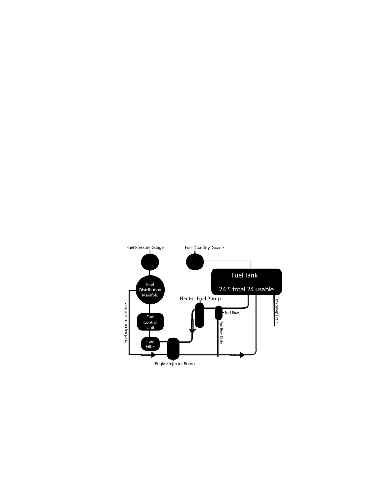
1.9 Fuel System
The aluminum tank is located behind the seats, below the baggage compartment. It holds a
total of 24.5 gallons of 100LL, 24 of which are usable. A grounding stud is located on the
underside of the fuselage near the trailing edge of the left hand wing The tank vent line runs

Copyright © 2019 by Midwest Air LLC
from the filler neck through the fuselage bottom skin to the exterior of the airplane. The vent
line is the translucent plastic hose adjacent to the left wing root. The tank has an integral
sump which must be drained prior to each flight, by pushing up on the brass tube which
protrudes through the underside of the fuselage.
Fuel is gravity fed from these outlets to a filter bowl (gascolator) and then to the electric fuel
pump. The filter bowl must be drained prior to each flight, by pushing up on the black rubber
tube that protrudes through the underside of the fuselage. An electric fuel pump primes the
engine for engine starting (Prime ON) and is used for low throttle operations (Fuel Pump
ON). When the pump is OFF, fuel flows through the pump internal bypass. From the electric
pump, fuel is delivered to the engine’s mechanical fuel pump by the fuel supply line. Fuel is
metered by the fuel control unit.
The DA20-C1 is equipped with a DUKES constant flow, vane type, two speed, and electric
fuel pump. This pump emits an audible whine when it is switched on. The pump’s high speed
setting is used for priming the engine prior to engine start. The prime setting is selected by
turning the FUEL PRIME switch ON. An amber annunciator indicates that FUEL PRIME ON
is selected. The pump’s low speed setting is required for maintaining positive fuel supply
system pressures at low throttle settings (approx. 1000RPM and less). Turning the priming
pump on while the engine is running, will enriches the mixture considerably. which may
cause rough engine operation or engine stoppage. It is therefore recommended that for
normal operations, the FUEL PRIME be turned OFF.
Instructor’s Note: Never dump sumped fuel back into the aircraft unless your strainer
has been cleaned prior to taking a fuel sample.
Figure 2: Diamond DA20-C1 fuel system diagram

Copyright © 2019 by Midwest Air LLC
1.10 Electrical System
A 12 V battery is connected to the master bus via the battery circuit breaker (50 amps). The
40 amp alternator is attached to the engine near the propeller hub. The alternator feeds the
main bus via the generator circuit breaker (50 Amps). Both circuit breakers can be triggered
manually. The GEN warning light is activated by an internal voltage regulator monitoring
circuit and illuminates when a generator fault occurs.
The voltmeter indicates the status of the electrical bus. It consists of a dial that is marked
numerically from 8-16 volts in divisions of 2. The scale is divided into three colored arcs to
indicate the seriousness of the bus condition. These arcs are:
Red for 8.0 - 11.0 volts
Yellow . . . . . . . for 11.0 - 12.5 volts
Green . . . . . . . . for 12.5 - 16.0
volts Redline at 16.1 volts
The ammeter indicates the charging (+) and discharging (-) of the battery. It consists of a
dial, which is marked numerically from -60 to 60 amps. The GEN warning light (red)
illuminates during alternator failure; with no output from the generator the only remaining
power source is the battery (20 amps for 30 minutes)
1.11 Ignition System
The engine is provided with two independent ignition systems. The two engine driven
magnetos are independent from the power supply system, and are in operation as soon as
the propeller is turning and the ignition switch is not off. This ensures safe engine operation
even in case of an electrical power failure.
1.12 Garmin G500 System
The G500 is comprised of six main components:
Primary Flight Display (PFD, left) and Multi-Function Display (MFD, right)
Attitude Heading Reference System (AHRS)
Air Data Computer
(ADC) Magnetometer
Temperature Probe
Garmin GNS 430 GPS
The PFD (left) shows primary flight information in place of traditional pitot-static and
gyroscopic instruments, and also provides an HSI for navigation.
The Attitude Heading Reference System (AHRS) contains tilt sensors, accelerometers, and
rate sensors similar to our modern cell phones to provide attitude and heading information
on the PFD.
The Air Data Computer (ADC) compiles information from the pitot-static system and an
outside air temperature sensor to provide pressure altitude, airspeed, vertical speed, and
outside air temperature on the PFD.
The magnetometer senses the earth’s magnetic field and sends data to the AHRS for

Copyright © 2019 by Midwest Air LLC
processing to determine the aircraft’s magnetic heading.
The temperature probe provides outside air temperature (OAT) data to the
ADC. The Garmin GNS 430 GPS provides input to the AHRS and PFD/MFD.
G500 equipped Diamonds do not have a conventional turn coordinator. A slip-skid indicator
is located at the top of the attitude indicator. Step on the “brick” instead of the “ball”. Use
the reference lines and the magenta line that appears above the heading indicator to identify
a standard rate or half-standard rate turn. Outside air temperature (OAT) displays on PFD
under the airspeed tape. Ground track can be identified on the heading indicator by a small
magenta diamond near the lubber line (only visible when ground track is different than
heading). The digital altitude and airspeed readouts are very sensitive and can cause some
pilots to continuously make corrections for insignificant deviations.
Figure 3: Garmin G500

Copyright © 2019 by Midwest Air LLC
2 Performance, Weight & Balance
2.1 Airspeed Limitations
Speed
KIAS
Remarks
VA
Maneuvering Speed
106
Do not make full or abrupt control movement
above this speed. Under certain conditions
the airplane may be overstressed by full
control movement.
VFE (Takeoff)
100
Do not exceed this speed with flaps in takeoff
position.
VFE (Landing)
78
Do not exceed this speed with flaps in
landing position.
VNO
Maximum Structural
Cruising Speed
118
Do not exceed this speed except in smooth
air, and then only with caution.
VNE
Never Exceed Speed
164
Do not exceed this speed in any operation.
VSO
Stall Speed (Landing
Configuration)
34
Minimum steady flight speed at which the
airplane is controllable in the landing
configuration.
VS
Stall Speed (Clean
Configuration)
42
Minimum steady flight speed at which the
airplane is controllable in the clean
configuration.
VG
Best Glide
73
Airspeed for best glide angle
Wing Flaps in CRUISE position.
VX
57
Best Angle of Climb.
VY
68
Best Rate of Climb.

Copyright © 2019 by Midwest Air LLC
2.2 Weight & Balance
Maximum Ramp Weight :1770 lbs (803 kg)
Maximum Takeoff Weight :1764 lbs (800 kg)
Maximum Landing Weight :1764 lbs (800 kg)
Maximum Weight in Baggage Compartment :44 lbs (20 kg)
Weight of 100LL Per Gallon :6 lbs
Weight of Oil Per Gallon :7.5 lbs
3 DA20 Procedures guide

Copyright © 2019 by Midwest Air LLC
3.1 Passenger Briefing
S Safety belt / harness usage
A Air vents –location and usage
F Fire extinguisher –location and usage
E Exits –canopy operation
T Talking –when to quiet and listen to radio
Y ”Your questions?” – anything they want to ask
Other notes:
•NO SMOKING
•Discuss pilot-in-command (PIC) authority, training/checkride
3.2 Flight Instrument Check
•Airspeed –reading zero
•Attitude indicator –blue over brown within 5 degrees in 5 minutes
•Altimeters –set & crosscheck (current baro setting) within 75 feet of field elevation
•VSI –reading zero (up to 100’ deviations are approved but must be taken into account
during flight)
•Turn coordinator –wings level ball in the center
•HSI/DG –aligned with the compass
•Compass –no cracks no leaks no bubbles, deviation card present
3.3 Flight instrument Check During Taxi
•Turn coordinator indicating a turn
•Inclinometer (Ball) indicating a skid
•Compass swinging freely
•HSI/DG turning freely
3.4 Pre-Takeoff Briefing
Engine failure or abnormality prior to rotation:
•Abort takeoff –throttle immediately closed Brake as required stop straight ahead

Copyright © 2019 by Midwest Air LLC
•If not enough runway to stop: Mixture to cutoff, fuel shut off, magnetos, and battery
master off avoid obstacles
Engine failure after rotation with sufficient runway remaining for a complete stop:
•Throttle immediately closed
•Land straight ahead, brake as required
Engine failure after rotation with no runway remaining:
•Maintain control/pitch for best glide
•Only shallow turns to avoid obstacles
•Flaps as necessary for safe touchdown
•Throttle closed
•Mixture to cutoff
•Fuel shut off, magnetos, and battery master off
•Touchdown at lowest speed possible

Copyright © 2019 by Midwest Air LLC
4 Takeoff Procedures
4.1 Normal Takeoff (Flaps T/O)
1. Select Flaps T/O◦
2. Line up on centerline positioning controls for wind
3. Smoothly apply full power
4. Check engine gauges
5. Right rudder as required for turning tendencies
6. “Airspeed Alive”
7. Start slow rotation at 44 KIAS
8. Accelerate to 68 KIAS (VY)
9. 400’ AGL – Flaps cruise.
10. 1,000’ AGL – “After Takeoff Checklist”

Copyright © 2019 by Midwest Air LLC
4.2 Short Field Takeoff (Flaps T/O)
1. Select Flaps T/O◦
2. Line up on centerline positioning controls for wind
3. Hold brakes
4. Smoothly apply full power
5. Check engine gauges
6. Release brakes
7. “Airspeed Alive”
8. Briskly rotate at 51 KIAS
9. Accelerate to 57 KIAS (VX)
10. When clear of obstacles, accelerate to 68 KIAS (VY)
11. 400’ AGL – Flaps cruise.
12. 1,000’ AGL – “After Takeoff Checklist”

Copyright © 2019 by Midwest Air LLC
4.3 Soft Field Takeoff (Flaps T/O)
1. Select Flaps T/O◦
2. Roll onto runway with full AFT stick –minimum braking –do not stop
3. Smoothly apply full power holding full AFT on the stick –check engine gauges
4. As nose lifts off, ease back pressure (keep nose wheel off the ground)
5. Lift off at the lowest possible airspeed –remain in ground effect
6. In ground effect, accelerate to 57 KIAS (VX), then begin climb
7. When clear of obstacles, accelerate to 68 KIAS (VY)
8. 400’ AGL – Flaps cruise.
9. 1,000’ AGL – “After Takeoff Checklist”

Copyright © 2019 by Midwest Air LLC
5 Landing Procedures
5.1 VFR Landing Briefing Procedure
Announce verbally:
1. Type of Approach & Landing Runway
2. Aiming & Touchdown Point
3. Wind Direction & Speed Pattern Altitude
4. Go-Around Criteria & Plan
Example: “This will be a normal flaps full landing on runway 13 with an intended touchdown
point of the one thousand foot markers, aiming point will be 3 stripes prior, we can expect
a left crosswind of 5 knots”.
Stabilized Approach
Definition: A stabilized approach is one in which the pilot establishes and maintains a
constant angle glide-path towards a predetermined point on the landing runway. It is based
on the pilot’s judgment of certain visual cues, and depends on a constant final descent
airspeed and configuration (FAA-H-8083-3A, p.8-7).
Approach Gust factors:
Slightly higher approach speeds should be used under turbulent or gusty wind conditions.
Add 1/2 the gust factor to the normal approach speed. For example, if the wind is reported 8
gusting to 18 knots, the gust factor is 10 knots. Add 1/2 the gust factor, 5 knots in this
example, to the normal approach speed.
5.2 Before Landing Checklist
This is a memory item that needs to get memorized.
Announce verbally:
1. Seat belts –fastened
2. Mixture set –RICH
3. Fuel pump –ON
4. Gen/Bat Master –ON
5. Magnetos –BOTH
6. Lights –as required
7. Flaps –as required

Copyright © 2019 by Midwest Air LLC
5.3 Normal Landing (Flaps LDG)
1. Complete the “Approach Checklist” before entering the airport; devote full attention to
aircraft control and traffic avoidance
2. Slow to 90 KIAS prior to entering downwind or traffic pattern and complete the before
landing checklist
3. Enter traffic pattern at published TPA (typically 1,000’ AGL)
4. Complete the “VFR Landing Brief” when established on the downwind
5. When abeam touchdown point, or on extended base, or on extended final (when
ready to descend out of pattern altitude) –Reduce power to 1500 RPM and select
Flaps T/O◦
6. Descend out of pattern altitude at 80 KIAS
7. Turn from downwind to base when touchdown point is approx. 45 degrees behind
(over the shoulder)
8. On base, select Flaps LDG◦and slow to 70 KIAS
9. Maintain 65 KIAS on final
10. Smoothly reduce power when approaching aiming point

Copyright © 2019 by Midwest Air LLC
5.4 Short Field Landing (Flaps LDG)
1. Complete the “Approach Checklist” before entering the airport; devote full attention to
aircraft control and traffic avoidance
2. Slow to 90 KIAS prior to entering downwind or traffic pattern and complete the before
landing checklist
3. Enter traffic pattern at published TPA (typically 1,000’ AGL)
4. Complete the “VFR Landing Checklist” when established on the downwind
5. When abeam touchdown point, or on extended base, or on extended final (when
ready to descend out of pattern altitude) –Reduce power to 1500 RPM and select
Flaps T/O◦
6. Descend out of pattern altitude at 80 KIAS
7. Turn from downwind to base when touchdown point is approx. 45 degrees behind
(over the shoulder)
8. On base, select Flaps LDG◦and slow to 70 KIAS
9. Maintain 60 KIAS on final
10. Smoothly reduce power when approaching aiming point
11. Touch down with minimal floating
12. Hold the stick full AFT, announce “simulate max braking and flaps up” (DO NOT SKID
THE TIRES)

Copyright © 2019 by Midwest Air LLC
5.5 Soft Field Landing (Flaps LDG)

Copyright © 2019 by Midwest Air LLC
1. Complete the “Approach Checklist” before entering the airport; devote full attention to
aircraft control and traffic avoidance
2. Slow to 90 KIAS prior to entering downwind or traffic pattern and complete the before
landing checklist
3. Enter traffic pattern at published TPA (typically 1,000’ AGL)
4. Complete the “VFR Landing Brief” when established on the downwind
5. When abeam touchdown point, or on extended base, or on extended final (when
ready to descend out of pattern altitude) –Reduce power to 1500 RPM and select
Flaps T/O◦
6. Descend out of pattern altitude at 80 KIAS
7. Turn from downwind to base when touchdown point is approx. 45 degrees behind
(over the shoulder)
8. On base, select Flaps LDG◦and slow to 70 KIAS
9. Maintain 60 KIAS on final
10. Smoothly reduce power when approaching aiming point
11. After touchdown –Gently apply full AFT stick to keep weight off the nose wheel

Copyright © 2019 by Midwest Air LLC
5.6 Power Off 180 Procedure
Table of contents