3
CONTENTS
CONTENTSCONTENTS
CONTENTS
INTRODUCTION .........................................................................................................................4
FEATURES ...............................................................................................................................4
FREEWAVE FULLY SUPERVISED WIRELESS ACCESSORIES .........................................................................5
USER MODE ............................................................................................................................5
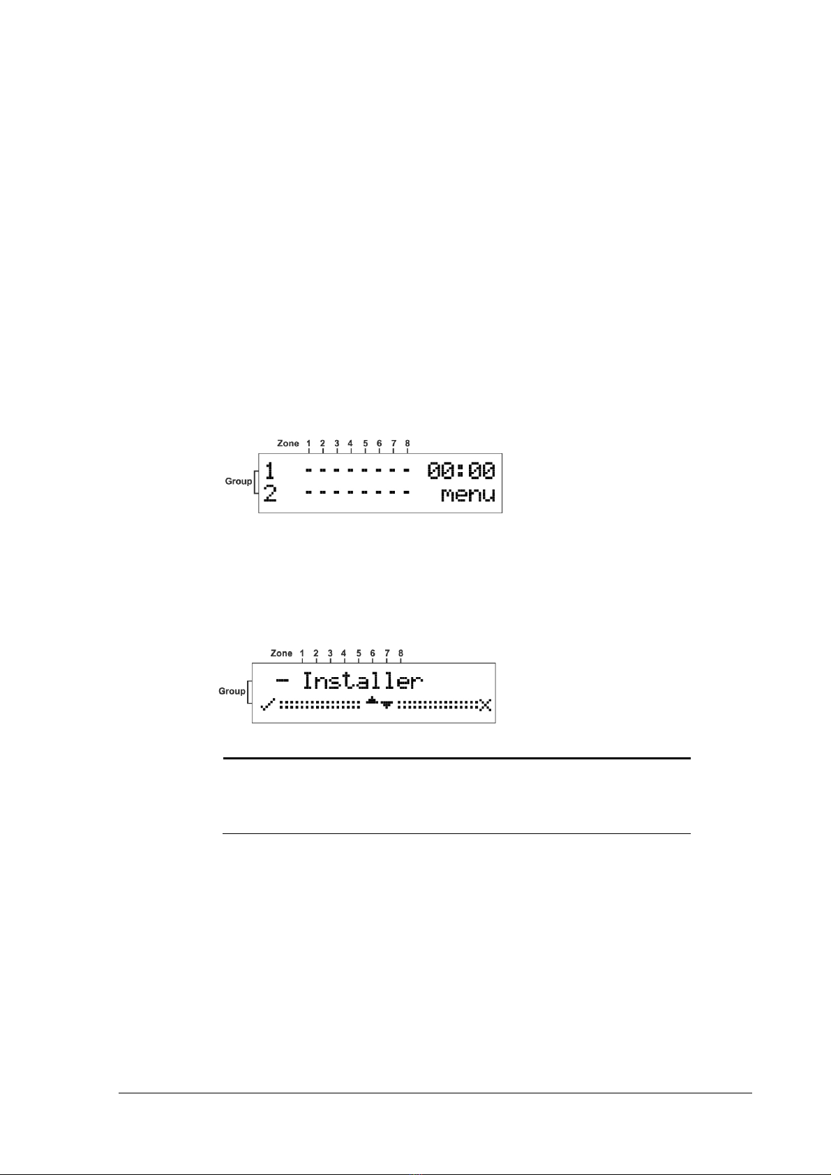
USING THE DISPLAY AND KEYPAD ...................................................................................................5
Navigating the Screens ........................................................................................................... 5
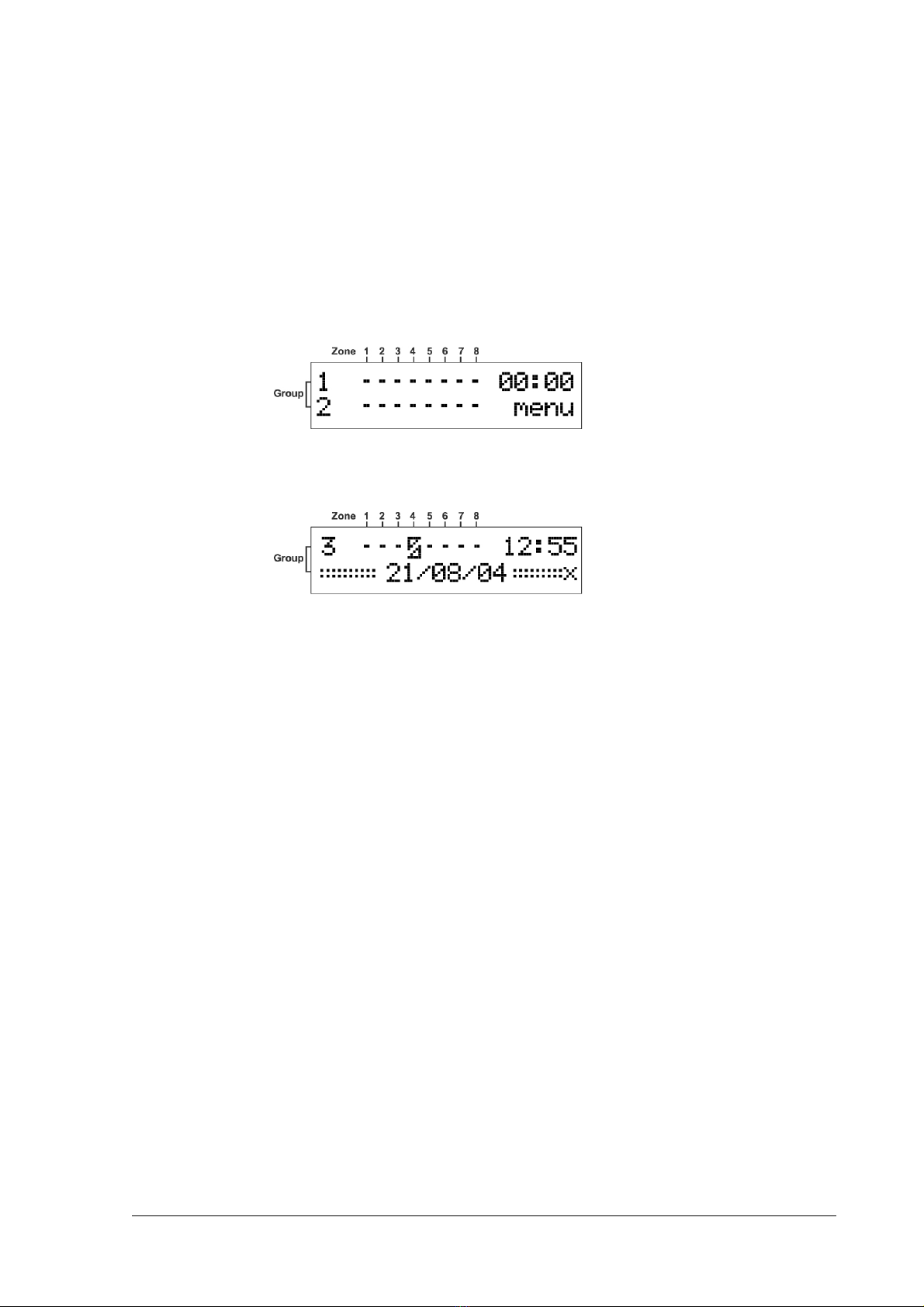
MEMORY (EVENT LOG)................................................................................................................6
Displaying the Event Log......................................................................................................... 6
Setting the Date and Time ......................................................................................................6
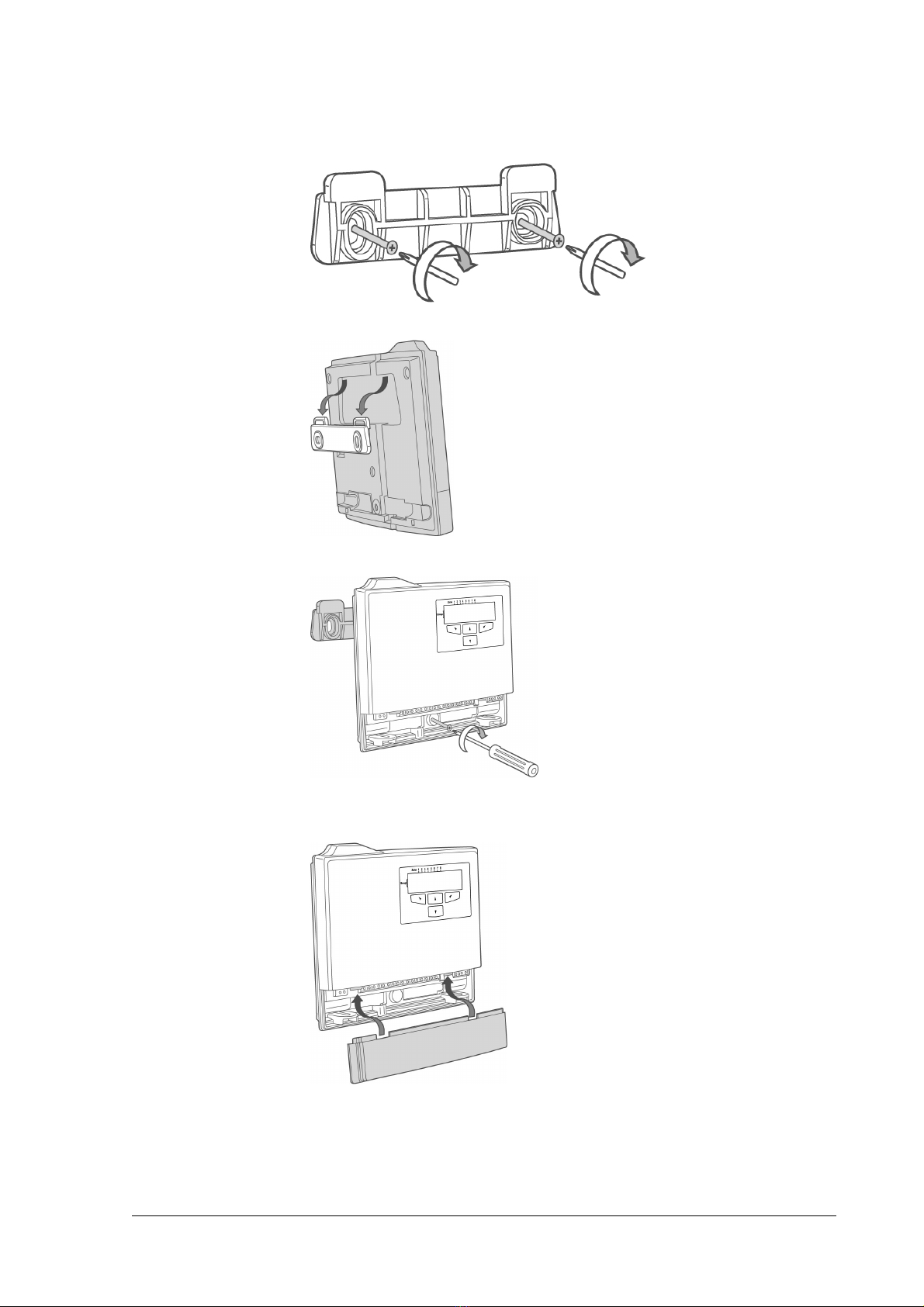
INSTALLING THE MERLI
INSTALLING THE MERLIINSTALLING THE MERLI
INSTALLING THE MERLIN PRO
N PRON PRO
N PRO ................................................................................................... 7
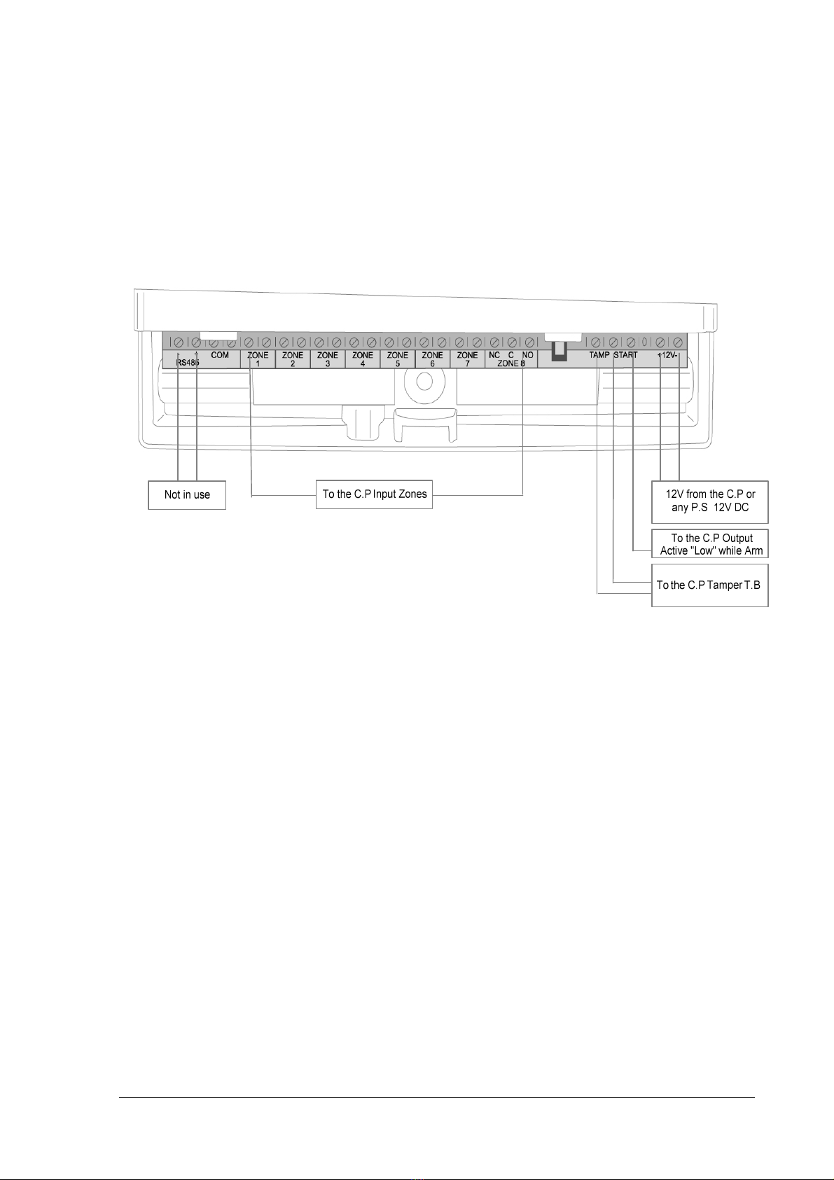
INSTALLATION DIAGRAMS.............................................................................................................8
PROGRAMME SEQUENCE LIST .......................................................................................................10
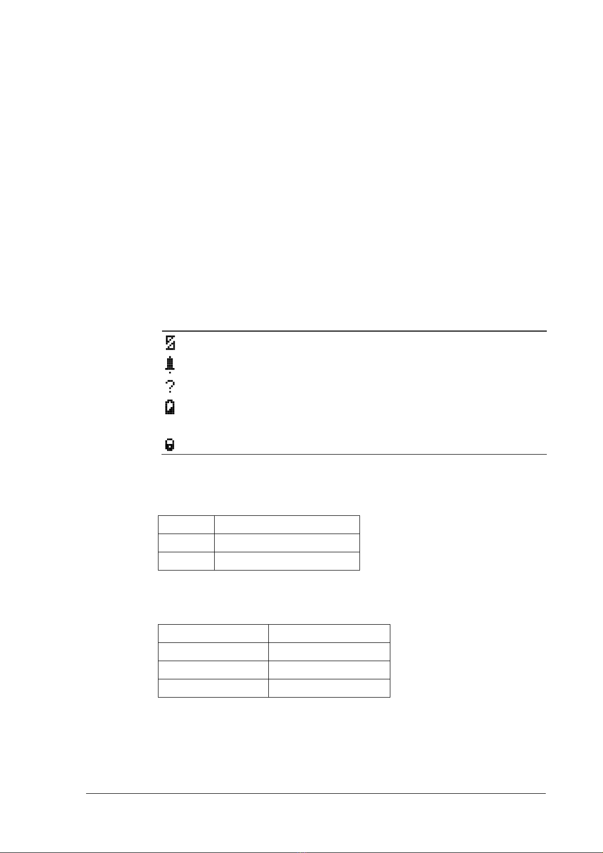
LCD Display Symbol Table......................................................................................................10
Entering Numbers ................................................................................................................. 10
SETTING THE CLOCK..................................................................................................................11
INSTALLER MODE ....................................................................................................................12
Accessing the Installer Mode................................................................................................. 12
Adding a Wireless Device (Add Zone) .................................................................................... 13
Adding a Remote Control key................................................................................................ 14
Clear Zone ............................................................................................................................ 16
Clear Remote........................................................................................................................ 17
Changing the Password......................................................................................................... 18
Checking the RSSI (Radio signal strength).............................................................................. 18
Clear History ......................................................................................................................... 19
Arm To Output ...................................................................................................................... 19
Buzzer Tie............................................................................................................................. 20
Remotes Log......................................................................................................................... 21
Version ................................................................................................................................. 21
Setting the Unit Defaults ....................................................................................................... 22
FUNCTIONS ...........................................................................................................................23
TECHNICAL
TECHNICALTECHNICAL
TECHNICAL SPECIFICATIONS
SPECIFICATIONSSPECIFICATIONS
SPECIFICATIONS .................................................................................................... 25
CROW ELECTRONIC ENGINEERING LTD. (CROW)WARRANTY POLICY CERTIFICATE .................................26