Crown 2/300 User manual

Product Registration: Register your new product at www.warranty.harmanpro.com.
Obtaining Other Language Versions: To obtain information in another language about the use of this product, please contact your local Crown
Distributor. If you need assistance locating your local distributor, please contact Crown at 574-294-8000 or visit www.crownaudio.com.
This manual does not include all of the details of design, production, or variations of the equipment. Nor does it cover every possible situation which may
arise during installation, operation, or maintenance.
The information provided in this manual was deemed accurate as of the publication date. However, updates to this information may have occurred. To
obtain the latest version of this manual, please visit the Crown website at www.crownaudio.com.
Trademark Notice: Com-Tech, BCA, Crown, Crown Audio, Amcron and Multi-Mode are registered trademarks of Crown International. DriveCore,
DriveCore Install, IQwic, PIP and PIP2 are trademarks of Crown International. Other trademarks are the property of their respective owners.
Some models may be exported under the name Amcron®
© 2016 by HARMAN International®, Inc. 1718 W. Mishawaka Rd., Elkhart, Indiana 46517-9439 U.S.A. Telephone: 574-294-8000
CDi DriveCore Series
Power Amplifiers
Operation Manual
5074176-A – 11/16
SERIAL NUMBERSERIAL NUMBER
BAR CODE
100-240V~50/60Hz 350W
1718 W. MISHAWAKA
RD.
CAUTION - TO REDUCE THE RISK OF ELECTRIC
SHOCK, GROUNDING OF T HE CENTER PIN
OF THIS P LUG MUST BE MAINTAIN ED
ATTENTION - POUR RÉDUIRE LE RISQUE DE CHOC
ÉLECTRIQUE LA FICHE CENTRALE LA PRISE DOIT Ê TRE
BRANCHÉE P OUR MAINT ENIR LA MISE À L A TERRE
WARNING
-
TO REDUCE THE RISK
OF FIRE OF ELECTRICAL SHOCK, DO
NOT EXPOSE THIS EQUIPMENT TO RAIN
OR MOISTURE.
AVERTISSEMENT
- ENERGIE
ELECTRIQUE DANGEREUSE` VOIR LE
CAHIER D’INSTRUCTIONS.
APPARATET MATILKOPLES JORDET
STIKKONTAKT.
APPARATEN SKALL ANSLUTAS TILL
JORDAT UTTAG.
LAITE ON LIITETTÄVÄ
SUOJAKOSKETTIMILLA VARUSTETTUUN
PISTORASIAAN.
RISK OF ELECTRIC
SHOCK
AVERTISSEMENT: RISQUE DE CHOC
ELECTRIQUE - NE PAS OUVRIR
CLASS 2 OUTPUT WIRING PERMITTED.
THIS DEVICE COMPLIES WITH PART 15 OFTHE FCC RULES.
OPERATION IS SUBJECT TOTHE FOLLOWING CONDITIONS.
1) THIS DEVICE MAY NOT CAUSE HARMFUL INTERFERENCE.
2) THIS DEVICE MUST ACCEPT ANY INTERFERENCE THAT
MAY CAUSE UNDESIRED OPERATION.
WARNING
OUTPUTOUTPUT INPUT
2 14 3
2 1
DUALDUAL
BRIDGE
OUTPUT
WIRING
ETHERNET
100Mb
ACT
GPIO/AUX
BLU linkIN OUT
OUT
12
IN
3
AMP STATUS
7
+3.3V
45
IN
6
SLEEP
8
SERIAL NUMBERSERIAL NUMBER
BAR CODE
100-240V~50/60Hz 350W
1718 W. MISHAWAKA RD.
ELKHART IN 46517 USA
CAUTION - TO REDUCE THE RISK OF ELECTRIC
SHOCK, GROUNDING OF T HE CENTER PIN
OF THIS P LUG MUST BE MAINTAIN ED
ATTENTION - POUR RÉDUIRE LE RISQUE DE CHOC
ÉLECTRIQUE LA FICHE CENTRALE LA PRISE DOIT Ê TRE
BRANCHÉE P OUR MAINT ENIR LA MISE À L A TERRE
WARNING
-
TO REDUCE THE RISK
OF FIRE OF ELECTRICAL SHOCK, DO
NOT EXPOSE THIS EQUIPMENT TO RAIN
OR MOISTURE.
AVERTISSEMENT
- ENERGIE
ELECTRIQUE DANGEREUSE` VOIR LE
CAHIER D’INSTRUCTIONS.
APPARATET MATILKOPLES JORDET
STIKKONTAKT.
APPARATEN SKALL ANSLUTAS TILL
JORDAT UTTAG.
LAITE ON LIITETTÄVÄ
SUOJAKOSKETTIMILLA VARUSTETTUUN
PISTORASIAAN.
RISK OF ELECTRIC
SHOCK
AVERTISSEMENT: RISQUE DE CHOC
ELECTRIQUE - NE PAS OUVRIR
CLASS 2 OUTPUT WIRING PERMITTED.
THIS DEVICE COMPLIES WITH PART 15 OFTHE FCC RULES.
OPERATION IS SUBJECT TOTHE FOLLOWING CONDITIONS.
1) THIS DEVICE MAY NOT CAUSE HARMFUL INTERFERENCE.
2) THIS DEVICE MUST ACCEPT ANY INTERFERENCE THAT
MAY CAUSE UNDESIRED OPERATION.
WARNING
OUTPUTOUTPUT INPUT
2 14 3
2 1
DUALDUAL
BRIDGE
OUTPUT
WIRING
ETHERNET
100Mb
ACT
GPIO/AUX
BLU linkIN OUT
OUT
12
IN
3
AMP STATUS
7
+3.3V
45
IN
6
SLEEP
8
• 2|300
• 2|300BL
• 2|600
• 2|600BL
• 4|300
• 4|300BL

CDi DriveCore Series Operation Manual
Welcome ���������������������������������������������� 1
Features ................................................................................ 1
How to Use this Manual......................................................... 1
Installing the Amp ����������������������������������� 2
Unpacking............................................................................. 2
Additional Materials .............................................................. 2
Installing the Amplifier .......................................................... 2
Proper Cooling...................................................................... 2
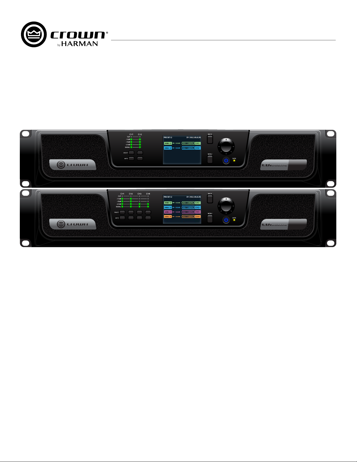
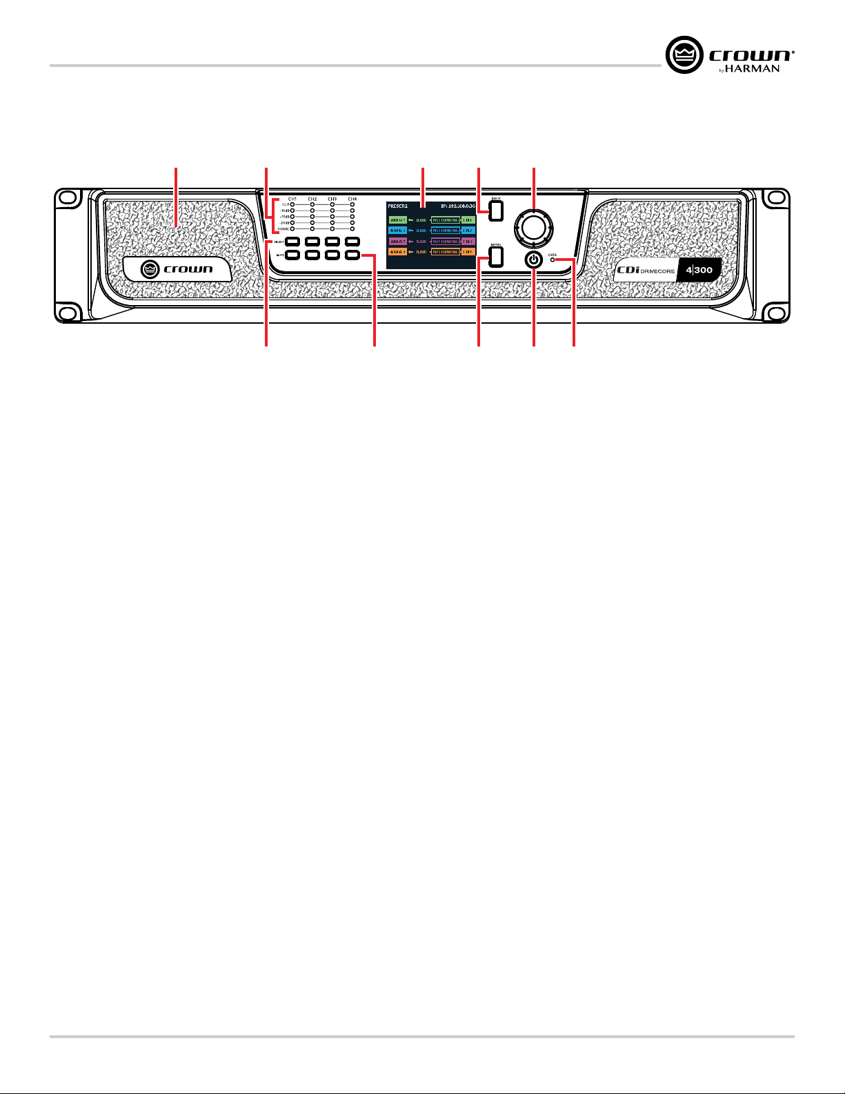
Front Panel Overview�������������������������������� 3
Rear Panel Overview �������������������������������� 4
Hardware Setup �������������������������������������� 5
Connecting the AC Power Cord ............................................. 5
Power Up Procedure.............................................................. 5
Precautions........................................................................... 6
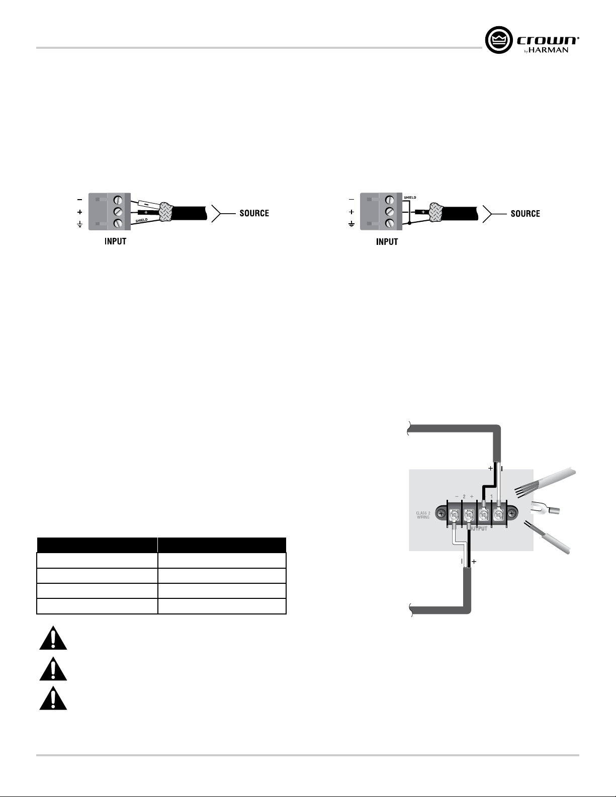
Wiring Input Connectors ....................................................... 7
Wiring Output Connectors..................................................... 7
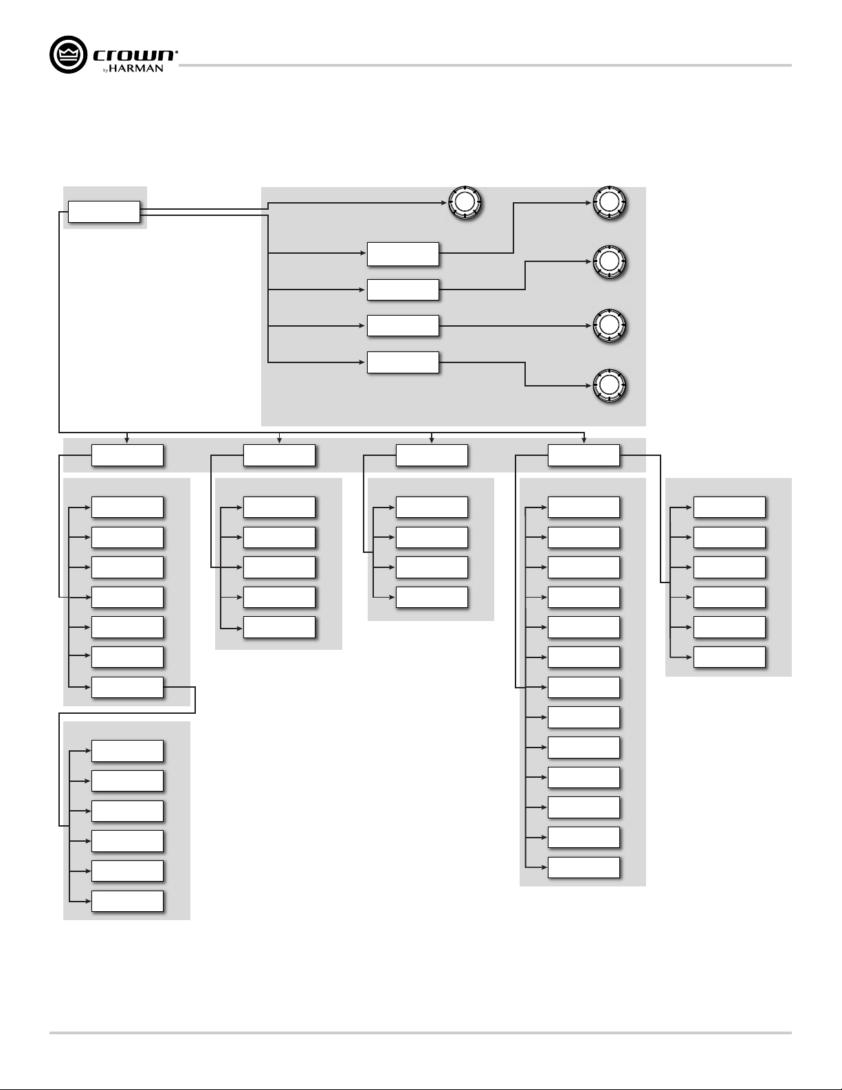
Front Panel Menus & Navigation Overview ������ 8
Menu Structure ..................................................................... 8
The Home Screen.................................................................. 9
Adjusting Channel Volume�������������������������10
Configuring the Amp ��������������������������������11
Using the Guided Setup....................................................... 11
Configuring Inputs & Outputs.............................................. 12
Configuring Amp Wiring & Bridge Mode........................ 13
Assigning Input Sources ................................................ 14
Configuring BLU link Settings........................................ 15
Configuring Output Modes............................................. 16
Configuring DSP................................................................. 16
Delay.............................................................................. 17
Crossover ...................................................................... 18
PEQ (Parametric EQ) ...................................................... 19
Limiter ........................................................................... 20
Installing Audio Architect & Configuring the
Network ���������������������������������������������21
Introduction to HiQnet Audio Architect................................. 21
Configuring Amplifier Network Settings............................... 22
Configuring the Network from the Front Panel ................ 22
Configuring the Network using NetSetter........................ 23
The NetSetter Grid..................................................... 25
Using HiQnet Audio Architect����������������������29
Offline & Online Operation Explained................................... 29
Going Online....................................................................... 30
Matching Devices........................................................... 30
Main CDi DriveCore Control Panel...................................... 31
Amplifier Information .......................................................... 32
Configuring Inputs & Outputs in Audio Architect ................. 33
Assigning Input Sources in Audio Architect.................... 33
Configuring Inputs......................................................... 34
Configuring BLU link Clock ........................................... 35
Configuring BLU link Outputs......................................... 35
Configuring Amp Wiring & Output Modes in Audio
Architect......................................................................... 36
Cascading Inputs ........................................................... 36
Configuring Outputs for Bridge Mono Operation ............ 37
Configuring Outputs for Low Z/High Z Operation............ 37
Crossover Panel.................................................................. 38
FIR Filters....................................................................... 38
Input/Output EQ Panels....................................................... 39
Input/Output Delay Panels................................................... 40
LevelMAX Panel.................................................................. 41
About the Transducer Thermal Limiter ............................ 41
Signal Generator Panel........................................................ 42
Managing Device & Preset Files.......................................... 43
Application Examples ������������������������������45
Dual Mode, Low Z (8Ω, 4Ω, or 2Ω)....................................... 45
Bridge Mono Mode, Low Z (16Ω, 8Ω, or 4Ω)........................ 46
Dual Mode, High Z (70Vrms/100Vrms) ............................... 47
Bridge Mono Mode, High Z (140Vrms/200Vrms) ................ 48
Using BLU link���������������������������������������49
BLU link Specifications ....................................................... 49
BLU link Latency ................................................................. 49
Making BLU link Connections............................................. 49
BLU link Port LED Indicators ............................................... 50
Mastership.......................................................................... 51
Fault Tolerance.................................................................... 51
BLU link Status.................................................................... 52
Device Presets ��������������������������������������53
Saving Device Presets......................................................... 53
Loading Device Presets....................................................... 54
System Settings�������������������������������������55
Lighting/Display Options .................................................... 55
Security/Front Panel Lockout .............................................. 56
Amplifier Diagnostics.......................................................... 57
Amp Gain Mode .................................................................. 57
Using the GPIO Control Port �����������������������58
GPIO Pinout, Specification, Use, & Configuration .............58
Using the AUX Port����������������������������������59
Sleep................................................................................... 59
Amp Status.......................................................................... 59
System Protection ����������������������������������60
Faults.................................................................................. 60
Thermal Limit...................................................................... 60
Auto-Insertion High-Pass Filters......................................... 60
AC Under/Over-Voltage Protection...................................... 60
Fan-Cooled Chassis............................................................ 60
Universal Switching Power Supply...................................... 61
Troubleshooting �������������������������������������62
Signal Path Block Diagram ������������������������64
Factory Reset ����������������������������������������65
Specifications ���������������������������������������66
Output Power: Dual Mode – All Channels Driven................. 66
Output Power: Bridge Mono Mode – All Channels Driven.... 66
Input Sensitivity .................................................................. 66
Performance Specifications................................................. 67
Dimensions......................................................................... 68
Warranty (United States Only) ��������������������69
Service �����������������������������������������������70
Worldwide Service .............................................................. 70
US and Canada Service ....................................................... 70
Service at a US or Canada Service Center............................ 70
Factory Service.................................................................... 70
Factory Service Shipping Instructions................................. 71
Packing Instructions............................................................ 71
Estimate Approval ............................................................... 71
Payment of Non-Warranty Repairs....................................... 71
Service Return Authorization Request �����������72
Open Source Disclaimer for HARMAN Products 73
GNU General Public License Version 2 ����������76
GNU General Public License Version 3 ����������81
Table of Contents
Table of Contents

Page 1
CDi DriveCore Series Operation Manual
Welcome
Welcome
SERIAL NUMBERSERIAL NUMBER
BAR CODE
100-240V~50/60Hz 350W
1718 W. MISHAWAKA
RD.
CAUTION - TO RE DUCE THE RISK O F ELECTRIC
SHOCK, GROUN DING OF THE CENTER PIN
OF THIS P LUG MUST BE MAINTAIN ED
ATTENTION - POUR RÉDUIRE LE RISQUE DE CHO C
ÉLEC TRIQUE LA FICHE CEN TRALE L A PRISE DOIT Ê TRE
BRANCHÉE P OUR MAINT ENIR LA MISE À L A TERRE
WARNING
-
TO REDUCE THE RISK
OF FIRE OF ELECTRICAL SHOCK, DO
NOT EXPOSE THIS EQUIPMENT TO
RAIN OR MOISTURE.
AVERTISSEMENT
- ENERGIE
ELECTRIQUE DANGEREUSE` VOIR LE
CAHIER D’INSTRUCTIONS.
APPARATET MA TILKOPLES JORDET
STIKKONTAKT.
APPARATEN SKALL ANSLUTAS TILL
JORDAT UTTAG.
LAITE ON LIITETTÄVÄ
SUOJAKOSKETTIMILLA
VARUSTETTUUN PISTORASIAAN.
RISK OF ELECTRIC
SHOCK
AVERTISSEMENT: RISQUE DE CHOC
ELECTRIQUE - NE PAS OUVRIR
CLASS 2 OUTPUT WIRING PERMITTED.
THIS DEVICE COMPLIES WITH PART 15 OF THE FCC RULES.
OPERATION IS SUBJECT TO THE FOLLOWING CONDITIONS.
1) THIS DEVICE MAY NOT CAUSE HARMFUL
INTERFERENCE.
2) THIS DEVICE MUST ACCEPT ANY INTERFERENCE
WARNING
OUTPUTOUTPUT INPUT
2 14 3
2 1
DUALDUAL
BRIDGE
OUTPUT
WIRING
ETHERNET
100Mb
ACT
GPIO/AUX
BLU linkIN OUT
OUT
12
IN
3
AMP STATUS
7
+3.3V
45
IN
6
SLEEP
8
Thank you for purchasing a Crown CDi DriveCore installation amplifier, one in a complete line of high-performance amplifiers based on exclusive
DriveCore technology. The CDi DriveCore Series amplifiers are designed, engineered, and manufactured to the industry’s highest quality standards and
offer system integrators with the advanced features and flexibility required for challenging 21st-century installed-sound applications. Versatile, compact,
and highly energy-efficient, CDi DriveCore Series amplifiers continue the unbroken Crown tradition of leadership in professional and commercial power
amplifier technology.
Features
• Exclusive multi-patented DriveCore™ Technology – The patented DriveCore integrated circuit combines hundreds of discrete circuits into one chip for
better performance, lower power consumption, and improved reliability
• BLU link digital audio transport – Up to 256 Channels of digital audio over Category 5e cabling (available on BLU link CDi DriveCore models)
• Supports configuration and control using HiQnet®Audio Architect™
• Monitoring and control over TCP/IP
• Color LCD and front panel user interface for amplifier configuration, control, and monitoring
• Programmable GPIO (general purpose input/output) control port
• Digital signal processing (Input/output EQ filters, crossover, input/output delay, LevelMAXTM limiters)
• Support for importing of FIR filter coefficients
• 20 device presets – 1 factory and 19 user
• 96kHz/32-bit floating-point signal processing
• Universal power supply with PFC for reduced current draw and industry-leading efficiency
• Remote power off – Sleep mode activated via AUX port
• 70Vrms/100Vrms direct drive
• Each channel individually selectable for Low Z or High Z operation
• Advanced protection circuits – Amplifier and loads are protected against shorted outputs, DC, mismatched loads, overheating, over/under-voltage,
and high-frequency overload
• Three year, no-fault transferable warranty – Your investment is fully protected
• Complies with GreenEdge™ by HARMAN – Environmentally friendly practices in design, manufacturing, and packaging complement energy-efficient
operation
How to Use this Manual
This manual provides the necessary information to safely and correctly setup and operate your Crown product. It does not cover every aspect of installation,
setup, or operation that might occur under every condition. For additional information, please contact technical support, your system installer, or retailer.
We strongly recommend you read all instructions, warnings, and cautions contained in this manual. Also, for your protection, please register your product
at www.warranty.harmanpro.com. And save your bill of sale — it’s your official proof of purchase.
If viewing this manual from a computer or mobile device which supports interactive PDFs, the Table of Contents, page references, figure references, and
URLs are all interactive and can be clicked on or pressed to navigate to the corresponding page or web URL.

Page 2 CDi DriveCore Series Operation Manual
Installing the Amp
Installing the Amp
Unpacking
Unpack your amplifier and inspect for any damage that may have occurred during transit. If damage is found, notify the shipping company immediately.
Only you can initiate a claim for shipping damage, though Crown will be happy to help as needed. If the product arrived showing signs of damage, save the
shipping carton for the shipper’s inspection.
We also recommend that you save all packing materials for use if you ever need to transport the unit. Never ship the unit without the factory carton and
packing materials.
Additional Materials
For installation, you will need the following (not supplied):
• Input wiring cables
• Output wiring cables
• Flathead screwdriver
• Phillips screwdriver
• Rack for mounting amplifier (or a stable surface for stacking)
• Category 5e or higher cabling
WARNING: Before you start to set up your amplier, read and observe the Important Safety
Instructions included in the box. These instructions can also be downloaded from the product
page at www.crownaudio.com.
Installing the Amplifier
CAUTION: Before you begin, make sure your amplifier is disconnected from the power source.
Mount the unit in a standard 19-inch (48.3 cm) equipment rack (EIA RS-310B). You can also place a single amp on a solid, stable surface or stack multiple
amps.
NOTE: Amplifiers should be supported at both the front and rear of the rack.
See "Dimensions" on page 68 for information on amplifier dimensions.
Proper Cooling
When using an equipment rack, mount units directly on top of each other. Close any open
spaces in the rack with blank panels. (Open spaces will reduce cooling efficiency.) DO NOT
block front or rear air vents.
The rack should be a minimum of 2 inches (5.1 cm) away from the amplifier, and the back of
the rack should be a minimum of 4 inches (10.2 cm) from the amplifier back panel.
Air flow is front to back as illustrated in Figure 1.
SERIALNUMBERSERIALNUMBER
BARCODE
100-240V
~
50/60Hz 350W
1718W.M ISHAWAKA
RD.
CAUTION-TO REDUCE THE RISK OF ELEC TRIC
SHOCK,GROUNDINGOF THE CENTER PIN
OFTHISPLUG MUST BE MAINTAINED
ATTENTION-POUR RÉDUIRE LE RISQU E DE CHOC
ÉLECTRIQUELAFICHE CENTR ALE LA PRISE DOIT ÊTRE
BRANCHÉEPOURMAINTENIR L A MISE À LA TERRE
WARNING
TOREDUCETHE RISK
OFFIREOF ELECTRICAL SHOCK, DO
NOTEXPOSETHIS EQUIPMENT TO
RAINORMOISTURE.
AVERTISSEMENT
CAHIERD’INSTRUCTIONS.
APPARATETMATILKOPLESJORDET
STIKKONTAKT.
APPARATENSKALLANSLUTASTILL
JORDATUTTAG.
LAITEONLIITETTÄVÄ
SUOJAKOSKETTIMILLA
VARUSTETTUUNPISTORASIAAN.
RISKOFELECTRIC
SHOCK
AVERTISSEMENT:RISQUEDE CHOC
CLASS2 OUTPUT WIRING PERMITTED.
THISDEVICECOMPLIES WITH PART 15 OFTHE FCC RULES.
OPERATIONISSUBJECT TOTHE FOLLOWING CONDITIONS.
INTERFERENCE.
WARNING
OUTPUTOUTPUT INPUT
214 3
2 1
DUALDUAL
BRIDGE
OUTPUT
WIRING
ETHERNET
100Mb
ACT
GPIO/AUX
BLUlinkIN OUT
OUT
12
IN
3
AMPSTATUS
7
+3.3V
45
IN
6
SLEEP
8
SERIALNUMBERSERIALNUMBER
BARCODE
100-240V
~
50/60Hz 350W
1718W.M ISHAWAKA
RD.
CAUTION-TO REDUCE THE RISK OF ELEC TRIC
SHOCK,GROUNDINGOF THE CENTER PIN
OFTHISPLUG MUST BE MAINTAINED
ATTENTION-POUR RÉDUIRE LE RISQU E DE CHOC
ÉLECTRIQUELAFICHE CENTR ALE LA PRISE DOIT ÊTRE
BRANCHÉEPOURMAINTENIR L A MISE À LA TERRE
WARNING
TOREDUCETHE RISK
OFFIREOF ELECTRICAL SHOCK, DO
NOTEXPOSETHIS EQUIPMENT TO
RAINORMOISTURE.
AVERTISSEMENT
CAHIERD’INSTRUCTIONS.
APPARATETMATILKOPLESJORDET
STIKKONTAKT.
APPARATENSKALLANSLUTASTILL
JORDATUTTAG.
LAITEONLIITETTÄVÄ
SUOJAKOSKETTIMILLA
VARUSTETTUUNPISTORASIAAN.
RISKOFELECTRIC
SHOCK
AVERTISSEMENT:RISQUEDE CHOC
CLASS2 OUTPUT WIRING PERMITTED.
THISDEVICECOMPLIES WITH PART 15 OFTHE FCC RULES.
OPERATIONISSUBJECT TOTHE FOLLOWING CONDITIONS.
INTERFERENCE.
WARNING
OUTPUTOUTPUT INPUT
214 3
2 1
DUALDUAL
BRIDGE
OUTPUT
WIRING
OUT
2
IN
3
AMPSTATUS
7
+3.3V
45
IN
6
SLEEP
8
100-240V
~
50/60Hz 350W
CAUTION-TO REDUCE THE RISK OF ELEC TRIC
SHOCK,GROUNDINGOF THE CENTER PIN
OFTHISPLUG MUST BE MAINTAINED
ATTENTION-POUR RÉDUIRE LE RISQU E DE CHOC
ÉLECTRIQUELAFICHE CENTR ALE LA PRISE DOIT ÊTRE
BRANCHÉEPOURMAINTENIR L A MISE À LA TERRE
Figure 1: Proper rack venting

Page 3
CDi DriveCore Series Operation Manual
Front Panel Overview
678
4
9 10
5
5
3
1 2
Figure 2: 4|300 front panel shown
1� Cooling Vents/Air Filters
Provides cooling air flow. Do not block or cover these vents. Air
filters are removable.
2� Signal Level LED Indicators
These LEDs indicate channel signal level as follows:
• Clip LED – Lights yellow if the input clips or red if the output
clips. Note that an output clip will always take priority over an
input clip.
• -10dB LED – Lights green when the output signal reaches a
level that is 10dB below full scale output of the amp.
• -15dB LED – Lights green when the output signal reaches a
level that is 15dB below full scale output of the amp.
• -20dB LED – Lights green when the output signal reaches a
level that is 20dB below full scale output of the amp.
• Signal LED –Lights green when signal is sensed at the input.
The threshold for lighting this LED is -40dBu.
NOTE: The full scale output of the amplifier may change depending
on the Low Z/High Z setting, as well as the amplifier model. See
"Conguring Outputs for Low Z/High Z Operation" on
page 37 for more information.
3� LCD (Display)
This color LCD provides product information and visual feedback for
operating the CDi DriveCore amplifier from the front panel.
4� Back Button
Press this button to navigate back one level when navigating menus.
5� Encoder
This encoder supports rotary and pushbutton operation. It is used to
navigate the CDi DriveCore's menus and select on-screen options. It
is also used to adjust individual channel or overall system volume.
6� Channel Select Buttons
Pressing one of these buttons will select the corresponding channel;
turning the ENCODER will then control the volume of the selected
channel.
Pressing and holding a CHANNEL SELECT button for 2 seconds
from the Home screen will display a Channel Details screen for
that channel. The Channel Details screen shows additional details
for the selected channel, including configured input source, output
mode, status, channel temperature, and channel volume. Note that
channel volume can also be controlled from this screen by turning
the Encoder.
7� Channel Mute Buttons
Pressing each of these buttons will mute/unmute the corresponding
amplifier output channel. Note that when a channel is muted, the
front panel SIGNAL LEDs will still light to indicate input signal level
presence, the CLIP LEDs will still light to indicate input clipping, and
the LCD will flash "Mute".
8� Menu Button
Pressing this button will enter the Main menu, where amplifier
settings can be edited.
9� Power Button
Turns the amplifier power on or off. The Power button has an
integrated power symbol that illuminates blue when the power is on
and green when the power is off. To prevent the unit from accidentally
being powered off, the Power button must be pressed and held for 2
seconds when powering off.
NOTE: The Power button is disabled when using the AUX port
Sleep circuit. See "Using the AUX Port" on page 59 for
more information.
10� Data LED
This LED will illuminate yellow when there is valid HiQnet data being
transmitted to/from the amplifier.
NOTE: 4-channel model shown. Indications per channel pair are identical for 2-channel models.

Page 4 CDi DriveCore Series Operation Manual
Rear Panel Overview
Rear Panel Overview
SERIAL NUMBERSERIAL NUMBER
BAR CODE
100-240V~50/60Hz 350W
1718 W. MISHAWAKA RD.
ELKHART IN 46517 USA
CAUTION - TO REDUCE THE RISK OF EL ECTRIC
SHOCK, GROUNDING OF THE CEN TER PIN
OF THIS PLUG MUST BE MAINTAINED
ATTENTION - POUR R ÉDUIRE LE RISQUE DE CHOC
ÉLECTRIQUE L A FICHE CENTRALE LA PRISE DOIT Ê TRE
BRANCHÉE POUR M AINTENIR LA MISE À LA TERRE
WARNING
TO REDUCE THE RISK
OF FIRE OF ELECTRICAL SHOCK, DO
NOT EXPOSE THIS EQUIPMENTTO
RAIN OR MOISTURE.
AVERTISSEMENT
CAHIER D’INSTRUCTIONS.
APPARATET MA TILKOPLES JORDET
STIKKONTAKT.
APPARATEN SKALL ANSLUTAS TILL
JORDAT UTTAG.
LAITE ON LIITETTÄVÄ
SUOJAKOSKETTIMILLA
VARUSTETTUUN PISTORASIAAN.
RISK OF ELECTRIC SHOCK
DO NOT OPEN
AVERTISSEMENT: RISQUE DE CHOC
CLASS 2 OUTPUT WIRING PERMITTED.
THIS DEVICE COMPLIES WITH PART 15 OF THE FCC RULES.
OPERATION IS SUBJECT TO THE FOLLOWING CONDITIONS.
INTERFERENCE.
WARNING
OUTPUTOUTPUT INPUT
2 14 3
2 1
DUALDUAL
BRIDGE
OUTPUT
WIRING
ETHERNET
100MbACT
GPIO/AUX
BLU linkIN OUT
OUT
12
IN
3
AMP STATUS
7
+3.3V
45
IN
6
SLEEP
8
5 6 7
1 2 3 4
Figure 3: 4|300BL rear panel shown
1� Cooling Fan Outlet
Outlet for cooling air flow. Do not block or cover this outlet.
2� BLU link Input/Output Ports*
These two RJ45 connectors are used for BLU link audio transport
and are available only on the BLU link CDi DriveCore amplifier
models. BLU link provides up to 256 channels of digital audio over
Category 5e wiring. For information on the port LED indicators, see
"BLU link Port LED Indicators" on page 50.
NOTE: BLU link audio will not pass through an Ethernet switch or
router. BLU link connections must be made directly between BLU link
devices.
3� General Purpose Input/Output (GPIO)
This 8-pin block connector combines the 2-in, 2-out GPIO with the
SLEEP and AMP STATUS pins from the AUX circuit. See "Using
the GPIO Control Port" on page 58 and "Using the AUX
Port" on page 59 for further information on configuring and
using these ports.
4� Ethernet (Network Control) Port*
Connect this RJ45 port to a computer or network for monitoring
and controlling the amplifier over Category 5e wiring via the Audio
Architect software. The integrated LEDs in this Ethernet port will light
as follows:
• Yellow LED
This LED lights when a network connection is established with
the computer or network, and will flash to indicate network
activity.
• Green LED
This LED indicates network speed and will light when
connected to a 100 Mb network or not light when connected to
a 10 Mb network.
NOTE: The Ethernet port is for network control only and will not
transmit or receive BLU link audio.
AC Power Inlet
Connect the included AC power cord to this standard 15A, IEC type
320 inlet. Supported mains voltage range is 100-240V~.
5� Output Terminal (Barrier Block) Connectors
One four-pole, touch-proof terminal strip per channel pair. Accepts
up to 10 AWG wire or terminal forks. See "Wiring Output
Connectors" on page 7 for information on wiring these
connectors.
6� Audio Input (Terminal Block) Connectors
Connect your audio source outputs to these inputs using the
provided plug-in connectors. One 6-pin plug-in connector can be
used per input pair. These inputs are high impedance, balanced
connections. See "Wiring Input Connectors" on page 7
for information on wiring these connectors.
*WARNING: Only connect to networks that remain inside the building.

Page 5
CDi DriveCore Series Operation Manual
Hardware Setup
Hardware Setup
Connecting the AC Power Cord
IMPORTANT: The amplifier output mode must be properly configured for the application before connecting the speakers and powering on the amplifier.
By default, all outputs are configured for Low Z operation. See "Conguring the Amp" on page 11 for more information.
Connect your amplifier to the AC mains power outlet using the supplied AC power cord. First, connect the IEC end of the cord to the IEC connector on the
amplifier. Then plug the other end of the cord to the AC mains.
WARNING: The third prong of the power connector (ground) is an important safety feature. Do not attempt to disable this ground connection
by using an adapter or other methods.
Make certain the AC mains voltage and current ratings are sufficient to deliver full power to all amplifiers. CDi DriveCore Series amplifiers use a universal
power supply. The AC voltage requirements are 100V-240V~, 50/60Hz (±10%). If the AC line voltage varies outside of this acceptable range, the amplifier’s
power supply will turn off and the blue Power LED will flash. The amplifier will turn back on when the AC line voltage returns to safe operating levels.
Power Up Procedure
When turning on the amplifier for the first time:
1� Ensure all connections are disconnected with the exception of the power cord.
2� Press the amplifier's POWER button. The Power indicator will light blue and the amplifier will boot as long as sufficient mains power is provided.
3� Once boot up is complete, turn the ENCODER counter-clockwise until all amp levels are set to -80dB in the front panel LCD.
4� Configure the amplifier as described in "Conguring the Amp" on page 11.
NOTE: The amplifier output mode must be properly configured for the application before connecting the speakers and powering on the amplifier. By
default, all outputs are configured for Low Z operation.
5� Once the amplifier has been properly configured for the application, turn off the power — by pressing and holding the Power button for 2 seconds —
then disconnect the power cord.
6� Turn down the level of your audio source.
7� Make all connections as described in "Wiring Input Connectors" and "Wiring Output Connectors" on page 7.
8� Once all connections have been made, reconnect the power cord and turn on the amplifier power.
9� Turn your audio source up to an optimum level. Refer to all device meters and ensure that at no point in the signal chain is the signal being clipped in
any way. If any of the amplifier's Clip indicators light yellow, reduce the source level until the Clip LEDs no longer light.
10� Turn the amplifier's ENCODER clockwise until the desired loudness or power level is achieved, while making sure the amplifier's clip LEDs do not
light.
IMPORTANT: Always turn off the amplifier — by pressing and holding the Power button for 2 seconds — and disconnect the power cord before making
any wiring or installation changes.
IMPORTANT: When powering a fully configured PA system, always turn the amplifiers on last and off first.
For help with determining your system’s optimum gain structure (signal levels) please refer to the Crown Amplifier Application Guide, available online at
www.crownaudio.com.

Page 6 CDi DriveCore Series Operation Manual
Hardware Setup
Precautions
Your amplifier is protected from internal and external faults, but you should still take the following precautions for optimum performance and safety:
1� Configure the amplifier for proper operation, including input and output wiring hookup. Improper wiring can result in serious operating difficulties.
For information on wiring and configuration, please consult "Wiring Input Connectors" and "Wiring Output Connectors" on page 7.
For advanced setup techniques, consult Crown’s Amplifier Application Guide available online at www.crownaudio.com.
2� Use care when making connections, selecting signal sources, and controlling the output level. The load you save may be your own!
3� Do not short the ground lead of an output cable to the input signal ground. This may form a ground loop and cause oscillations.
4� Never connect the output to a power supply, battery, or power main� Electrical shock may result�
5� Tampering with the circuitry or making unauthorized circuit changes may be hazardous and invalidate all agency listings.
6� Do not operate the amplifier with the Clip LEDs constantly flashing.
7� Do not overdrive the mixer, which will cause clipped signal to be sent to the amplifier. Such signals will be reproduced with extreme accuracy, and
loudspeaker damage may result.
8� Do not operate the amplifier with less than the rated load impedance. Due to the amplifier’s output protection, such a configuration may result in
premature clipping and speaker damage.
REMEMBER: Crown is not liable for damage that results from overdriving other system components.

Page 7
CDi DriveCore Series Operation Manual
Hardware Setup
Wiring Input Connectors
Crown recommends using pre-built or professionally wired balanced cables (two-conductor plus shield). Balanced wiring provides better rejection of
unwanted noise and hum, however, unbalanced line may also be used.
Use 6-pin plug-in cable ends at the amp input connectors. A male connector is supplied for each input of your model of amplifier. Additional connectors
are available from Crown (P/N 5024623).
Figure 4 shows connector pin assignments for balanced wiring and Figure 5 shows connector pin assignments for unbalanced wiring. Note that for
bridge mono operation, only the odd-numbered input channels (1,3) should be wired for each bridged pair.
Figure 4: Balanced wiring Figure 5: Unbalanced wiring
Wiring Output Connectors
IMPORTANT: The amplifier output mode (Low Z, 70V, 100V) must be properly configured for the application before connecting the speakers. By default,
all outputs are configured for Low Z operation. See "Conguring the Amp" on page 11 for more information.
Before making any output connections, ensure the power cord is disconnected from the amplifier and carefully review the total impedance for loudspeakers
connected to each amplifier output. If multiple loudspeakers are connected to an output in Low Z mode (i.e., in series, parallel, or series-parallel), be certain
the total system impedance is within allowed specification for the output. When multiple loudspeakers are connected to one output in High Z mode, be
certain total tapped power is below the rated power output for the channel. See "Specications" on page 66 for supported load specifications.
NOTE: The Crown-designed output cover does not need to be removed to connect the output wiring.
Crown recommends using the included terminal fork connectors and two-conductor or four-
conductor, heavy gauge speaker wire. You may use terminal forks up to 10 AWG or bare wire
for your output connectors (see Figure 6). For best results, Crown recommends Panduit part
#PV10-6LF-L or equivalent terminal fork. For bare wire, it is highly recommended that output
wiring is tinned. To reduce strain on input and output wiring, Crown recommends the use of
horizontal lacer bars. For best results, Crown recommends Middle Atlantic®part# LBP-4R90
or equivalent horizontal lacer bar.
For low-impedance loads, refer to the table below and select the appropriate size of wire based
on the distance from amplifier to speaker.
Distance Wire Size
Up to 25 ft. (7.6m) 16 AWG
26-40 ft. (7.9-12.2m) 14 AWG
41-60 ft. (12.5-18.3m) 12 AWG
> 60 ft (18.3m) 10 AWG
CAUTION: Never use shielded cable for output wiring.
CAUTION: Never connect the speaker return to the chassis of the amplifier, or damage to the amplifier may result.
NOTE: Custom wiring should only be performed by qualified personnel. Class 2 output wiring is required.
For application-specific output connection diagrams, including how to wire outputs for bridge mono operation, see "Application Examples" on page
45.
Figure 6: Wiring output connectors

Page 8 CDi DriveCore Series Operation Manual
Front Panel Menus & Navigation Overview
Menu Structure
The below diagram shows the CDi DriveCore's front panel menu structure, as well as how to navigate and control channel volume.
EDIT DSP MENU
SYSTEM MENU
Network
Load Preset
Guided Setup
Input Source
Amp Wiring
(Y, Bridge)
Save Preset
Cong (DHCP)
IP Address
Input Delay
Input PEQ
Output PEQ
Output Delay
Limiter
Crossover
Press MENU ButtonSelect from list using ENCODER*Select from list using ENCODER*
Select from list using ENCODER*
*Turn then press the ENCODER to make selections.
Note: BLU link options available in BLU link CDi DriveCore models only.
Note: Channels 3 and 4 available in 4-channel CDi DriveCore models only.
BLU LINK STATUS MENU
BLU link
Input Port
Status
Current Sample
Rate
Input Corrected
Count
Input Error Count
Input Error Reset
Output Error Reset
Output Corrected
Count
Output Error Count
Master Mac
Address
Mac Address
Version
Output Port
Status
Master Priority
BLU LINK SETTINGS MENU
BLU Link Out 1
Channel / Source
Sample Rate
BLU Link Out 4
Channel / Source
BLU Link Out 3
Channel / Source
BLU Link Out 2
Channel / Source
Priority
Select from list using ENCODER*
Press CH1 SELECT Button
(hold button for CH1 info)
Turn ENCODER
Press CH2 SELECT Button
(hold button for CH2 info)
Press CH3 SELECT Button
(hold button for CH3 info)
Press CH4 SELECT Button
(hold button for CH4 info)
HOME VOLUME Turn ENCODER
Turn ENCODER
Turn ENCODER
Turn ENCODER
Ch. 2 Selected
Ch. 3 Selected
Ch. 4 Selected
Ch. 1 Selected
Adjusts system volume
(aects all channels)
Adjusts Channel 1
Volume
Adjusts Channel 2
Volume
Adjusts Channel 3
Volume
Adjusts Channel 4
Volume
Home Screen
System Settings
Select from list using ENCODER*
SYSTEM SETTINGS MENU
Security
Lighting / Display
Options
Diagnostics
Amp Gain Mode
Edit DSP
Output Mode
(70V / 100V)
Subnet Mask
HiQnet Address
Gateway
NETWORK MENUCONFIGURE AMPLIFIER MENU
Congure Amplier
Figure 7: Menu structure diagram

Page 9
CDi DriveCore Series Operation Manual
Front Panel Menus & Navigation Overview
The Home Screen
The Home screen (shown in Figure 8) is the first screen displayed in the CDi DriveCore's
front panel display once the amplifier has completed the boot sequence.
From the Home screen, the ENCODER can be turned to adjust system volume, the
CHANNEL SELECT buttons can be pressed to adjust individual channel volume using the
ENCODER, or the MENU button can be pressed to enter the Main menu to configure and
view information about the amplifier.
The Home screen shows at-a-glance amplifier configuration information, as shown in
Figure 9. Here you can see the currently loaded device preset, device IP address, CDi
DriveCore configuration, channel volume settings, and more.
NOTE: Throughout sections of this manual, some illustrations and text will refer to
channel pair 1-2 only. Note that connections and settings for channels 3-4 (available on
4-channel CDi DriveCore models) are identical. Each channel can be configured
independently in all models.
Figure 8: Home screen
Current Device Preset Device IP Address
Channel Volume Settings
Error Messages Are Displayed Here
Configuration
Figure 9: Home screen layout

Page 10 CDi DriveCore Series Operation Manual
Adjusting Channel Volume
Channel volume can either be controlled globally or independently per channel. The volume range is from -80dB to 0dB. For gain structure purposes, it is
important to note that volume adjustment occurs at the end of the DSP signal chain and before output limiting.
To adjust system (global) volume:
1� From the Home screen, turn the ENCODER. The volumes for all channels will be adjusted respectively.
SERIAL NUMBERSERIAL NUMBER
BAR CODE
100-240V~50/60Hz 350W
1718 W. MISHAWAKA
RD.
CAUTION - TO REDUCE THE RISK OF ELECTRIC
SHOCK, GROUNDING OF THE CENTER PIN
OF THIS PLUG MUST BE MAINTAINED
ATTENTION - POUR RÉDUIRE LE RISQUE DE CHOC
ÉLECTRIQUE LA FICHE CENTRALE LA PRISE DOIT ÊTRE
BRANCHÉE POUR MAINTENIR LA MISE À LA TERRE
WARNING
-
TO REDUCE THE RISK
OF FIRE OF ELECTRICAL SHOCK, DO
NOT EXPOSE THIS EQUIPMENT TO
RAIN OR MOISTURE.
AVERTISSEMENT
- ENERGIE
ELECTRIQUE DANGEREUSE` VOIR LE
CAHIER D’INSTRUCTIONS.
APPARATET MA TILKOPLES JORDET
STIKKONTAKT.
APPARATEN SKALL ANSLUTAS TILL
JORDAT UTTAG.
LAITE ON LIITETTÄVÄ
SUOJAKOSKETTIMILLA
VARUSTETTUUN PISTORASIAAN.
RISK OF ELECTRIC
SHOCK
AVERTISSEMENT: RISQUE DE CHOC
ELECTRIQUE - NE PAS OUVRIR
CLASS 2 OUTPUT WIRING PERMITTED.
THIS DEVICE COMPLIES WITH PART 15 OF THE FCC RULES.
OPERATION IS SUBJECT TO THE FOLLOWING CONDITIONS.
1) THIS DEVICE MAY NOT CAUSE HARMFUL
INTERFERENCE.
2) THIS DEVICE MUST ACCEPT ANY INTERFERENCE
WARNING
OUTPUTOUTPUT INPUT
2 14 3
2 1
DUALDUAL
BRIDGE
OUTPUT
WIRING
ETHERNET
100Mb
ACT
GPIO/AUX
BLU linkIN OUT
OUT
12
IN
3
AMP STATUS
7
+3.3V
45
IN
6
SLEEP
8
NOTE: When adjusting system volume, all independent channel volume settings are adjusted relative to each other. This means that the minimum/
maximum global volume limits are governed by the channel with the highest or lowest volume setting.
To adjust the volume of a particular channel:
1� Select one of the channels using the corresponding SELECT button — the selected channel will now be highlighted in the display.
SERIAL NUMBERSERIAL NUMBER
BAR CODE
100-240V~50/60Hz 350W
1718 W. MISHAWAKA
RD.
CAUTION - TO REDUCE THE RISK OF ELECTRIC
SHOCK, GROUNDING OF THE CENTER PIN
OF THIS PLUG MUST BE MAINTAINED
ATTENTION - POUR RÉDUIRE LE RISQUE DE CHOC
ÉLECTRIQUE LA FICHE CENTRALE LA PRISE DOIT ÊTRE
BRANCHÉE POUR MAINTENIR LA MISE À LA TERRE
WARNING
-
TO REDUCE THE RISK
OF FIRE OF ELECTRICAL SHOCK, DO
NOT EXPOSE THIS EQUIPMENT TO
RAIN OR MOISTURE.
AVERTISSEMENT
- ENERGIE
ELECTRIQUE DANGEREUSE` VOIR LE
CAHIER D’INSTRUCTIONS.
APPARATET MA TILKOPLES JORDET
STIKKONTAKT.
APPARATEN SKALL ANSLUTAS TILL
JORDAT UTTAG.
LAITE ON LIITETTÄVÄ
SUOJAKOSKETTIMILLA
VARUSTETTUUN PISTORASIAAN.
RISK OF ELECTRIC
SHOCK
AVERTISSEMENT: RISQUE DE CHOC
ELECTRIQUE - NE PAS OUVRIR
CLASS 2 OUTPUT WIRING PERMITTED.
THIS DEVICE COMPLIES WITH PART 15 OF THE FCC RULES.
OPERATION IS SUBJECT TO THE FOLLOWING CONDITIONS.
1) THIS DEVICE MAY NOT CAUSE HARMFUL
INTERFERENCE.
2) THIS DEVICE MUST ACCEPT ANY INTERFERENCE
WARNING
OUTPUTOUTPUT INPUT
2 14 3
2 1
DUALDUAL
BRIDGE
OUTPUT
WIRING
ETHERNET
100Mb
ACT
GPIO/AUX
BLU linkIN OUT
OUT
12
IN
3
AMP STATUS
7
+3.3V
45
IN
6
SLEEP
8
TIP: An alternative method for adjusting channel volume is to press and hold one of the channel SELECT buttons to bring up the Channel screen.
2� Turn the ENCODER to adjust the selected channel's volume.
SERIAL NUMBERSERIAL NUMBER
BAR CODE
100-240V~50/60Hz 350W
1718 W. MISHAWAKA
RD.
CAUTION - TO REDUCE THE RISK OF ELECTRIC
SHOCK, GROUNDING OF THE CENTER PIN
OF THIS PLUG MUST BE MAINTAINED
ATTENTION - POUR RÉDUIRE LE RISQUE DE CHOC
ÉLECTRIQUE LA FICHE CENTRALE LA PRISE DOIT ÊTRE
BRANCHÉE POUR MAINTENIR LA MISE À LA TERRE
WARNING
-
TO REDUCE THE RISK
OF FIRE OF ELECTRICAL SHOCK, DO
NOT EXPOSE THIS EQUIPMENT TO
RAIN OR MOISTURE.
AVERTISSEMENT
- ENERGIE
ELECTRIQUE DANGEREUSE` VOIR LE
CAHIER D’INSTRUCTIONS.
APPARATET MA TILKOPLES JORDET
STIKKONTAKT.
APPARATEN SKALL ANSLUTAS TILL
JORDAT UTTAG.
LAITE ON LIITETTÄVÄ
SUOJAKOSKETTIMILLA
VARUSTETTUUN PISTORASIAAN.
RISK OF ELECTRIC
SHOCK
AVERTISSEMENT: RISQUE DE CHOC
ELECTRIQUE - NE PAS OUVRIR
CLASS 2 OUTPUT WIRING PERMITTED.
THIS DEVICE COMPLIES WITH PART 15 OF THE FCC RULES.
OPERATION IS SUBJECT TO THE FOLLOWING CONDITIONS.
1) THIS DEVICE MAY NOT CAUSE HARMFUL
INTERFERENCE.
2) THIS DEVICE MUST ACCEPT ANY INTERFERENCE
WARNING
OUTPUTOUTPUT INPUT
2 14 3
2 1
DUALDUAL
BRIDGE
OUTPUT
WIRING
ETHERNET
100Mb
ACT
GPIO/AUX
BLU linkIN OUT
OUT
12
IN
3
AMP STATUS
7
+3.3V
45
IN
6
SLEEP
8
3� When done, press the BACK button to deselect the channel.

Page 11
CDi DriveCore Series Operation Manual
Conguring the Amp
Conguring the Amp
This section of the manual describes how to configure the CDi DriveCore amplifier for your application using the front panel user interface. This includes
assigning input channels, editing internal routing and DSP settings, and configuring output mode settings. CDi DriveCore Series amplifiers can be
configured using the built-in Guided Setup or manually using the individual menu options in the Configure Amplifier menu (see Figure 10). Configuration
can also be performed from a PC using HiQnet Audio Architect. For information on configuring the CDi DriveCore amplifiers using Audio Architect, see
"Installing Audio Architect & Conguring the Network" on page 21.
Using the Guided Setup
The Guided Setup walks you through all the steps to configure the amplifier. This includes
assigning input channels, configuring internal DSP wiring and settings, and configuring
output operation.
To congure the amplier using the Guided Setup:
1� From the Home screen, press the MENU button.
2� Select the “Configure Amplifier” option from the menu using the ENCODER.
3� Select the "Guided Setup" option from the menu.
4� Follow the on-screen steps, making selections with the ENCODER. If you wish to exit
the Guided Setup at any time, press the MENU button.
NOTE: After completing the Guided Setup, configuration settings will be retained after power cycling the amp. However, it's a good idea to save the
configuration. The configuration must be saved before loading another device preset or the settings will be lost. See "Saving Device Presets" on
page 53 for information on saving device presets.
The following sections of this manual will discuss the menus used for configuring the CDi DriveCore amplifier manually.
Figure 10: Configure Amplifier menu

Page 12 CDi DriveCore Series Operation Manual
Conguring the Amp
Configuring Inputs & Outputs
The CDi DriveCore amplifiers ship from the
factory with each output channel sourced
from its respective analog input (e.g., analog
input 1 goes to output 1, etc.), as shown in
Figure 11.
When viewing the Home screen, signal flow
is represented by lines that travel from the
input source (leftmost box) to the channel
output (rightmost box).
Additional amplifier configuration information
can be seen at-a-glance on the Home screen,
as shown in Figure 12.
Analog 1 Source Input
Channel Assignment
Signal Routing
Output Channel 1
Figure 11: Default CDi DriveCore configuration
Current Device Preset
Input Channel
Assignment
Signal Wiring
("Y'ed" inputs shown)
Lightning Bolt Indicates
Output Configured for
High Z Operation
Ganged Block Indicates
Output is Configured for
Bridge Mono Operation
IP Address
No Speaker
Tuning/DSP Used
Figure 12: CDi DriveCore configuration example viewed from the front panel Home screen

Page 13
CDi DriveCore Series Operation Manual
Conguring the Amp
Configuring Amp Wiring & Bridge Mode
From the Amp Wiring Setup screen (see Figure 13), input wiring can be configured. Here
you can configure an input to feed multiple outputs (referred to as "Y'ing" the signal).
Bridge mono operation can also be configured from this screen. Bridging a pair of amplifier
outputs will increase the power and voltage available at the output.
To congure input wiring and/or bridge mode:
1� From the Home screen, press the MENU button.
2� Select the “Configure Amplifier” option from the menu using the ENCODER.
3� Select the "Amp Wiring" option from the menu.
4� Select the desired options for your application, making selections with the ENCODER.
5� When done, select "Done" at the bottom of the screen.
Available input options:
• Y 1+2
• Y 2+3*
• Y 3+4*
Available output options:
• Bridge 1+2
• Bridge 3+4*
For information on configuring signal routing and bridge mode settings in Audio Architect, see "Conguring Amp Wiring & Output Modes in
Audio Architect" on page 36.
*Channel 3 and 4 options available in 4-channel CDi DriveCore models only.
Figure 13: Amp Wiring Setup screen

Page 14 CDi DriveCore Series Operation Manual
Conguring the Amp
Assigning Input Sources
Input sources can be assigned from the Input Source screen (see Figure 14). The default
preset (Preset 1) is configured with all analog inputs feeding their respective output
channels.
To assign input sources:
1� From the Home screen, press the MENU button.
2� Select the "Configure Amplifier" option from the menu using the ENCODER.
3� Select the "Input Source" option.
4� Use the ENCODER to select each input channel block and edit the input channel
source assignment.
TIP: When assigning a BLU link input channel, the "BLU" option must first be
selected from the list, then the ENCODER must be pressed. Turning the ENCODER
will then select the desired BLU link channel from the list.
5� When done, select "Done" at the bottom of the screen.
Available options:
• Analog 1
• Analog 2
• Analog 1+2 (mono summed)
• Analog 3*
• Analog 4*
• Analog 3+4* (mono summed)
• Any available BLU link channel**
• None
For information on assigning input sources in Audio Architect, see "Assigning Input Sources in Audio Architect" on page 33.
*Channel 3 and 4 options available in 4-channel CDi DriveCore models only.
**BLU link options available in BLU link CDi DriveCore models only. BLU link channels 129-256 not available when operating a 96kHz BLU link bus.
Figure 14: Input Source screen

Page 15
CDi DriveCore Series Operation Manual
Conguring the Amp
Configuring BLU link Settings
The BLU link Settings menu is only available in BLU link CDi DriveCore models. From the
BLU link Settings menu (Figure 15), BLU link sample rate, clock priority, and outputs can
be configured.
To congure BLU link settings:
1� From the Home screen, press the MENU button.
2� Select the "BLU link" option from the menu using the ENCODER.
3� Select the "BLU link Settings" option from the menu.
4� Select the desired options for your application, making selections with the ENCODER.
5� When done, select "Done" at the bottom of the screen.
Available options:
• Sample Rate (48kHz, 96kHz)
Sets the BLU link sample rate in the amplifier. Sample rate can be set to 48kHz (default) or 96kHz. When set to 48kHz, the amplifier can access BLU
link channels 1-256. When set to 96kHz, the amplifier can access BLU link channels 1-128.
NOTE: The sample rate must be set to match all other devices on the BLU link bus in order to pass BLU link audio.
NOTE: The CDi DriveCore amplifiers process audio using a fixed 96kHz internal sampling rate. When using a BLU link sample rate of 48kHz, the
audio signal from the BLU link bus will be sample rate converted from 48kHz up to 96kHz when entering the amp, and any audio signals sent from the
amp back to the BLU link bus will be converted from 96kHz down to 48kHz.
NOTE: If the amp is configured to use any BLU link channels between 129-256 and the sample rate is then changed from 48kHz to 96kHz, all BLU
link assignments above 128 will default back to an "unassigned" state since they will no longer be applicable at 96kHz.
• Priority (0-254)
Determines which device on the BLU link bus will provide audio clock for the entire bus. The higher the value, the higher the priority. Under
certain conditions, such as when two devices have the same Priority settings, other factors may be used to determine BLU link clock priority
(see"Mastership" on page 51 for more information).
• BLU link Output Channel 1-4* (Off, 1-254 @ 48kHz / 1-128 @ 96kHz)
The CDi DriveCore amplifiers are capable of outputting up to 2 channels (2-channel models) or 4 channels (4-channel models) of audio onto the BLU
link bus. These options allow you to assign the desired BLU link output channels. Channels 1-256 are available when using a 48kHz BLU link sample
rate and channels 1-128 are available when using a 96kHz BLU link sample rate.
• BLU link Output Source 1-4*
These options allow you to select the source to route to each BLU link output channel, with the following options available:
• Analog Input 1-4*(routes the pre-processed audio signal from the input)
• Amp Output 1-4* (routes the same audio signal present at the amplifier outputs)
For information on routing BLU link channels to the amplifier's inputs, see "Assigning Input Sources" on page 14.
For information on configuring BLU link output settings in Audio Architect, see "Conguring BLU link Outputs" on page 35.
*Channel 3 and 4 options available in 4-channel CDi DriveCore models only.
Figure 15: BLU link Settings menu

Page 16 CDi DriveCore Series Operation Manual
Conguring the Amp
Configuring Output Modes
From the Output Mode Setup screen (see Figure 16), outputs can be configured for Low
Z or High Z operation. By default, the CDi DriveCore amplifiers are configured for Low Z
operation on all outputs.
To congure output mode settings:
1� From the Home screen, press the MENU button.
2� Select the "Configure Amplifier" option from the menu using the ENCODER.
3� Select the "Output Mode (70V/100V)" option from the menu.
4� Use the ENCODER to navigate, make selections, and edit settings.
5� When done, select "Done" at the bottom of the screen.
Available options:
• LoZ, 70V, 100V
Configures the output for the application type. Select the "LoZ" option for conventional low-impedance (2/4/8Ω) passive speakers, or choose the
appropriate voltage setting if configuring the output for a high-impedance (contsant-voltage) install application.
NOTE: If a pair of outputs are configured for bridge mono operation, selecting the 70V option will provide 140V and selecting the 100V option will
provide 200V.
For additional information on output modes and configuring output mode settings in Audio Architect, see "Conguring Amp Wiring & Output
Modes in Audio Architect" on page 36.
Configuring DSP
From the Edit DSP menu (see Figure 17) you can manually edit crossover, delay, and
limiter settings to optimize the loudspeakers. Note that this screen shows the status of each
DSP module (block). When a module is darkened, it is bypassed. When a module is bright,
it is turned on.
To manually edit DSP settings:
1� From the Home screen, press the MENU button.
2� Select the "Configure Amplifier" option from the menu using the ENCODER.
3� Select the "Edit DSP" option from the menu.
4� Use the ENCODER to select the module you wish to edit.
5� Use the ENCODER to navigate, make selections, and edit settings.
6� When done, select "Done" at the bottom of the screen.
Figure 16: Output Mode Setup screen
Figure 17: Edit DSP screen

Page 17
CDi DriveCore Series Operation Manual
Conguring the Amp
Delay
The CDi DriveCore amplifiers have an Input Delay (pre-crossover) and Output Delay (post-
crossover) DSP module for each channel. Each is selectable when navigating the Edit DSP
screen (see Figure 17). Once an Input or Output Delay module has been selected, delay
settings can be edited from the Delay screen (see Figure 18).
The Output Delay can be used to time-align the various drivers in a multi-way speaker
system. A total of up to 100ms of delay time is available in each Output Delay. The Input
Delay can be used for delaying the system to the stage backline, delay fills, or whenever
more delay time is required than the Output Delay has to offer. The Input Delay provide an
additional 1 second of delay time for each channel. Delay can be adjusted in milliseconds,
feet, or meters.
To edit delay settings:
1� From the Home screen, press the MENU button.
2� Select the "Configure Amplifier" option from the menu using the ENCODER.
3� Select the "Edit DSP" option from the menu.
4� Select the "Input Delay" or "Output Delay" icon for the channel you wish to edit.
5� Use the ENCODER to navigate, make selections, and edit settings.
6� When done, select "Done" at the bottom of the screen.
Available options/parameters:
• Enable (Off, On)
Turns the Delay on or off.
• Seconds (Input Delay: 0 – 1sec, Output Delay: 0 – 100ms)
Adjusts the delay time in milliseconds.
• Feet (Input Delay: 0 – 1127ft, Output Delay: 0 – 112�7ft)
Adjusts the delay time in feet.
• Meters (Input Delay: 0 – 343m, Output Delay: 0 – 34�3m)
Adjusts the delay time in meters.
For information on editing these settings in Audio Architect, see "Input/Output Delay Panels" on page 40.
Figure 18: Delay screen

Page 18 CDi DriveCore Series Operation Manual
Conguring the Amp
Crossover
Crossover filter settings can be edited from the Crossover screen (see Figure 19).
Crossover filters are used to restrict the range of frequencies sent to a loudspeaker or driver
for protection and sound optimization.
To edit crossover settings:
1� From the Home screen, press the MENU button.
2� Select the "Configure Amplifier" option from the menu using the ENCODER.
3� Select the "Edit DSP" option from the menu.
4� Select the "XOVER" icon for the channel you wish to edit.
5� Use the ENCODER to navigate, make selections, and edit settings.
6� When done, select "Done" at the bottom of the screen.
Available options/parameters:
• HP Enable (Off, On)
Enables or disables the high-pass filter.
• HP Type (Bessel 12 – 48dB/octave, Butterworth 6 – 48dB/octave, Linkwitz-Riley 12 – 48dB/octave)
Selects the high-pass filter's type and slope rate in dB/octave.
• HP Freq (16Hz – 20kHz)
Sets the high-pass filter's corner frequency.
• LP Enable (Off, On)
Enables or disables the low-pass filter.
• LP Type (Bessel 12 – 48dB/octave, Butterworth 6 – 48dB/octave, Linkwitz-Riley 12 – 48dB/octave)
Selects the low-pass filter's type and slope rate in dB/octave.
• LP Freq (16Hz – 20kHz)
Sets the low-pass filter's corner frequency.
• Gain (-60 to 24dB)
Adjusts the crossover output gain, pre limiter.
• Polarity (Normal, Inverted)
Selects between normal or inverted polarity for the selected output.
See "Crossover Panel" on page 38 for information on editing the Crossover in Audio Architect.
Figure 19: Crossover screen
This manual suits for next models
5
Table of contents
Other Crown Amplifier manuals

Crown
Crown Class-I User manual

Crown
Crown 140MPA User manual

Crown
Crown CTs 1200 User manual

Crown
Crown 133472-1A User guide

Crown
Crown XLi 800 User manual

Crown
Crown I-Tech 8000 User manual

Crown
Crown Belchfire Series BF-6000 SUX User manual

Crown
Crown Macro-Tech 3600 VZ User manual

Crown
Crown K0862-1 User manual

Crown
Crown MA-12000i User manual

Crown
Crown 1400 CSL User manual

Crown
Crown SL-1 Quick start guide

Crown
Crown XLS 202 User manual

Crown
Crown Pulse 4X300 User manual

Crown
Crown I-Tech I-T4000 User manual

Crown
Crown PSA-2 User manual

Crown
Crown XS500 User manual

Crown
Crown 660A User manual

Crown
Crown D-150 User manual

Crown
Crown CROWN K Series User manual