Sunfire Cinema Grand Power Supply Energy Load Invariant High Fidelity Super Definition Power... User manual

0
1
0
0
2
0
0
3
0
0
4
0
0
5
0
0
JOULES
Power Supply Energy
LoadInvariant HighFidelity SuperDefinitionPowerAmplifier
Sunfire
Cinema Grand
Four Hundred Wattsper Channel by Seven Channels
Signature400~seven
Cinema Grand
Signature 400 ~ seven
and 200 ~ seven
seven

User's Manual
2
Safety
Instructions
1. Read Instructions -– All the safety
and operation instructions should be
read before the SunÞre Component is
operated.
2. Retain Instructions — The safety
and operating instructions should be
kept for future reference.
3. Heed Warnings — All warnings on
the Component and in these operating
instructions should be followed.
4. Follow Instructions — All operat-
ing and other instructions should be
followed.
5. Water and Moisture — The
Component should not be used near
water - for example, near a bathtub,
washbowl, kitchen sink, laundry tub, in
a wet basement, or near a swimming
pool, etc.
6. Ventilation — The Component
should be situated so that its location
or position does not interfere with its
proper ventilation. For example, the
Component should not be situated on
a bed, sofa, rug, or similar surface that
may block any ventilation openings; or
placed in a built-in installation such as
a bookcase, cabinet, or closed equip-
ment rack that may impede the ßow of
air through ventilation openings.
7. Heat — The Component should be
situated away from heat sources such
as radiators, or other devices which
produce heat.
8. Power Sources — The Component
should be connected to a power sup-
ply only of the type described in these
operation instructions or as marked on
the Component.
9. Power Cord Protection — Power-
supply cords should be routed so that
they are not likely to be walked upon
or pinched by items placed upon or
against them, paying particular at-
tention to cords at plugs, convenience
receptacles, and the point where they
exit the Component.
10. Cleaning — The Compo-
nent should be cleaned only as
recommended in this manual.
11. Non-use Periods—The power
cord of the Component should be un-
plugged from the outlet when unused
for a long period of time.
12. Object and Liquid Entry — Care
should be taken so that objects do not
fall into and liquids are not spilled into
the inside of the Component.
13. Damage Requiring Service
— The Component should be serviced
only by qualiÞed service personnel
when:
A. The power-supply cord or the plug
has been damaged; or
B. Objects have fallen, or liquid has
spilled into the Component; or
C. The Component has been exposed
to rain; or
D. The Component does not appear to
operate normally
or exhibits a marked change in perfor-
mance; or
E. The Component has been dropped,
or its cabinet damaged.
14. Servicing — The user should not
attempt to service the Component
beyond those means described in this
operating manual. All other servicing
should be referred to qualiÞed service
personnel.
SAFETY

User's Manual 3
15. To prevent electric shock, do not
use this polarized plug with an exten-
sion cord, receptacle or other outlet
unless the blades can be fully inserted
to prevent blade exposure.
Pour préevenir les chocs électriques
ne pas utiliser cette Þche polariseé
avec un prolongateur, un prise de
courant ou une autre sortie de cou-
rant, sauf si les lames peuvent être
insérées à fond sans laisser aucune
parIIIe à découvert.
16. Grounding or Polarization —
Precautions should be taken so that
the grounding or polarization means
of the Component is not defeated.
This apparatus does not exceed the
Class A/Class B (whichever is ap-
plicable) limits for radio noise emissions
from digital apparatus as set out in the
radio interference regulations of the Ca-
nadian Department of Communications.
WARNING – TO REDUCE THE RISK OF FIRE OR ELECTRIC SHOCK,
DO NOT EXPOSE THIS APPLIANCE TO RAIN OR MOISTURE.
CAUTION: TO PREVENT ELECTRIC SHOCK, MATCH WIDE BLADE
OF PLUG TO WIDE SLOT, FULLY INSERT.
ATTENTION: POUR ÉVITER LES CHOCS ÉLECTRIQUES, INTRO-
DUIRE LA LAME LA PLUS LARGE DE LA FICHE DANS LA BORNE
CORRESPONDANTE DE LA PRISE ET POUSSER JUSQU’AU FOND.
ATTENTION — Le présent appar-
eil numérique n'émet pas de bruits
radioélectriques dépassant las limites
applicables aux appareils numériques
de class A/de class B (selon le cas)
prescrites dans le règlement sur le
brouillage radioélectrique édicté par
les ministere des communications du
Canada.
SAFETY
Safety Instructions................................... 2-3
Chapter 1: Introduction ...............................4
Cinema Grand Editions ..............................5
Unpacking and Installation .........................6
Front Panel Features..................................7
Rear Panel Features ..................................8
Chapter 2: System ConÞgurations ...........10
Appendix:
Series and Parallel ...................................15
Troubleshooting Guide .............................16
SpeciÞcations ...........................................18
Limited Warranty ......................................19
Service Assistance ...................................19
Please read the Safety Instructions
carefully before connecting and
using your SunÞre AmpliÞer.
Chapter 1 is a general introduction
to the features, details and installa-
tion of your ampliÞer.
Chapter 2 shows some typical con-
nections to a preampliÞer and
speakers.
The Appendix shows some addition-
al information, including a trouble-
shooting guide, the Warranty, and
service assistance details.
To Þnd out more about this and other
SunÞre products, please visit our
website: www.sunÞre.com
Contents

User's Manual
4
CHAPTER 1
Dear Friend,
Thank you for purchasing my SunÞre Cinema Grand seven channel power ampliÞer. I hope you en-
joy it and the music it makes as much as I have enjoyed creating it for you.
This magniÞcent ampliÞer represents my very latest thinking - and my best ampliÞer design ever.
I’ve spent over twenty years developing it, and cannot imagine how I could make it any better, or
reÞne it any further. No matter what, its performance is, at Þrst, somewhat difÞcult to believe.
The Signature 400~seven can produce 400 watts rms per channel into 8 ohms and 800 watts
rms into 4 ohms.
The 200~seven can produce 200 watts rms per channel into 8 ohms, and 400 watts rms into 4
ohms.
The big breakthrough feature of the Cinema Grand is its uncanny tracking downconverter, which
uses 18 Herculean Mosfets in the Signature 400~seven and 12 in the 200~seven. This allows the
Cinema Grand to produce phenominal power output, without the heat generated by conventional
designs.
The circuit boards are heavy glass epoxy, double sided, with a Faraday shield on the back side.
All resistors in the signal path are 1% tolerance, metal-Þlm. Critical capacitors are Þlm devices with
high dielectric strength and ultra low absorption characteristics. An enormous Cinema Grand power
source built around a massive power transformer provides the ultimate muscle for limitless dynamics.
I could go on and on, but here’s the best part: I’ve included two kinds of outputs on the front left
and front right channels:
(1) a standard voltage-source (i.e., near zero impedance) output for all typical applications and:
(2) a higher-impedance current-source output, which many prefer for electrostatic, planar
magnetic, or ribbon speakers. Or you can biwire your system with the voltage source driving
the woofer(s) and the current source driving the upper part of the system. In many cases this
provides by far the best possible interface between the ampliÞer and the speaker system.
Whichever way you decide to hook up the SunÞre Cinema Grand, it will create a multilayered
soundstage that is deep, wide, three-dimensional, and utterly believable. The optional current-source
output can coax forth a sensuous, delicately detailed musical voice long associated with low-powered
classic tube ampliÞers. (The current-source characteristic of vacuum tubes is the dominant factor in
the soundstage delivery of classic tube ampliÞers).
Bob Carver, AmpliÞer Designer, Physicist
Introduction

User's Manual 5
CHAPTER 1
Cinema Grand Editions
The Cinema Grand seven chan-
nel power ampliÞer is available in two
editions:
• Signature 400~seven
• 200~seven
The Signature 400~seven has twice
the power output, and uses heavier
output terminals compared to the
200~seven. Each Signature 400~sev-
en is personally signed on the front
panel by Bob Carver.
This manual uses illustrations of the
Signature 400~seven. The operational
details, features, and connections to
loudspeakers and preampliÞers are
the same for both models. 200~seven
200 Watts per channel into 8 Ω
400 Watts per channel into 4 Ω
Signature 400~seven
400 Watts per channel into 8 Ω
800 Watts per channel into 4 Ω
0
1
0
0
2
0
0
3
0
0
4
0
0
5
0
0
JOULES
Power Supply Energy
Load Invariant High Fidelity Super Definition Power Amplifier
Sunfire
Cinema Grand
Four Hundred Watts per Channel by Seven Channels
200 ~ seven
0
1
0
0
2
0
0
3
0
0
4
0
0
5
0
0
JOULES
Power Supply Energy
Load Invariant High Fidelity Super Definition Power Amplifier
Sunfire
Cinema Grand
Four Hundred Watts per Channel by Seven Channels
Signature 400 ~ seven

User's Manual
6
Installation
Read and follow all safety instruc-
tions shown on pages 2 and 3.
Observe the following precautions
when choosing a location for your
Cinema Grand AmpliÞer:
• Protect it from prolonged
exposure to direct sunlight and
other direct sources of heat,
such as heating vents and
radiators.
• Do not expose the unit to rain
or moisture. If ßuid or a for-
eign object should enter the
unit, immediately turn off the
power and contact your SunÞre
Dealer.
• Avoid excessive exposure to
extreme cold or dust.
• Do not place heavy objects on
top of the unit.
• Allow adequate ventilation
around the ampliÞer; do not
cover the ventilation slots.
AC Power Considerations
Ensure that the unit is plugged into
an outlet capable of supplying the cor-
rect voltage speciÞed for your model.
The outlet should be capable of sup-
plying 15 amps for the 120 V model,
8 amps for the 230 V model.
Care
If you need to clean the front sur-
face, Þrst turn off the power and then
use a dry soft cloth, rubbing with the
grain. Be careful not to scratch the
display window.
Connection Tips
Before setting up your new system,
please consider the following :
Always make sure that your
components are all turned
OFF before making or
changing connections.
• Make sure that the power
cords of all your components
are attached to the same outlet
or at least to the same circuit.
This will reduce the possibility
of a ground loop in the system.
Make sure that the total cur-
rent draw does not exceed
the current rating of your AC
outlet or power strip.
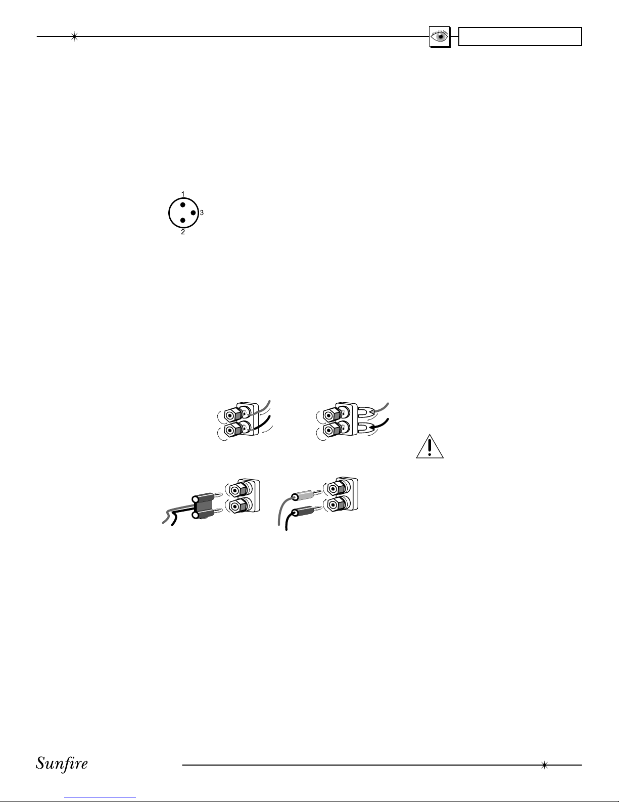
• Use the XLR inputs if your
preampliÞer has XLR outputs.
These balanced connections
provide superior noise rejec-
tion.
• Whenever possible, keep the
power cords away from the
signal cables or speaker wires
to prevent any hum or audio
interference being heard in the
speakers.
• Choose reliable hookup cables,
also called patch cords or RCA
cables. They should be fully
shielded and as short as pos-
sible for the job.
• Some patch cords can be a
very tight Þt and there is usu-
ally a preferred method of get-
ting them off. Some have to be
removed with a twisting action.
Be gentle or you may damage
the jacks of the ampliÞer or
your other components.
• Some special patch cords
can only be hooked up in one
direction, these are usually
marked with arrows.
• It is usual for the right patch
cord plugs to be red and the
left connections to be white,
grey or black. Video connec-
tions are usually yellow.
Unpacking
Your SunÞre AmpliÞer should reach
you in perfect condition. If you do
notice any shipping damage, please
contact your SunÞre Dealer immedi-
ately.
Gently lift out the unit and remove
all the packing material and acces-
sories. It is important to save all the
packing materials and the box in case
your ampliÞer ever needs to be moved
or shipped for repair.
Make sure that you keep your sales
receipt. It is the only way to establish
the duration of your Limited Warranty
and it may come in useful for insur-
ance purposes.
Please take a moment to Þll out and
mail the SunÞre Customer Response
card. Also read the serial number
located on the rear panel or the under-
side of the chassis,and record it here:
Serial #:
___________________________
Purchased at:
___________________________
___________________________
___________________________
___________________________
Date: _______________________
CHAPTER 1

User's Manual 7
Front Panel Features
Overview
Your Cinema Grand AmpliÞer has
seven channels of power ampliÞca-
tion combined in one chassis for the
purpose of reproducing music or video
soundtracks. It accepts line level
signals from a controlling preampliÞer
and ampliÞes them to a higher level,
suitable for driving powerful stereo
and Home Theater speakers.
Meter
The front panel meter indicates the
total energy available from the track-
ing downconverter power supply. It is
calibrated in Joules and will normally
indicate approximately 480 Joules
for the Signature 400~seven, and
400 Joules for the 200~seven. Note
that the needle does not move under
normal use.
Crystal Base
The glass base is intended to en-
sure proper airßow under the ampli-
Þer. It prevents any carpeting from
restricting the airßow.
If you choose to place the unit on a
shelf or other hard surface, the base
will isolate the amp from vibration and
will help make an attractive installa-
tion.
Illumination
The meter is illuminated by an
incandescent lamp operating at a
very warm color temperature. I have
been inßuenced by the scale lighting
of classic electronic equipment from
the 1950’s, with their warm dim glow,
usually with a “headlight effect” from
the lamp. I incorporated that historical
look and feel into this meter lighting. It
is decidedly not “evenly back-lit,” nor
with a cool to cold color temperature. I
hope you like my unusual meter light-
ing treatment.
A switch has been provided on the
underside of the unit toward the front.
This switch gives you the ability to
dim the meter lamp to reduce distrac-
tions in a Home Theater environment.
I like the brighter of the two settings,
as it illuminates the meter nicely and
matches my other SunÞre equipment.
Feel free to choose the setting that
suits you.
CHAPTER 1
0
1
0
0
2
0
0
3
0
0
4
0
0
5
0
0
JOULES
Power Supply Energy
Load Invariant High Fidelity Super Definition Power Amplifier
Sunfire
Cinema Grand
Four Hundred Watts per Channel by Seven Channels
Signature 400 ~ seven

User's Manual
8
Rear Panel Features
1. AUTO/ON/OFF Switch
Your Cinema Grand AmpliÞer is
designed with an automatic on/off
circuit.
• In the AUTO-ON position, the
ampliÞer will automatically turn
on if an audio signal is pres-
ent at any of the inputs, or if it
receives a 12 VDC input volt-
age at the trigger inputs. The
ampliÞer will automatically turn
off after a few seconds if the
trigger voltage is removed, or
after approximately 30 minutes
in the absence of an audio
signal.
• In the ON position, the ampli-
Þer is always on, regardless of
input signals or 12 VDC trigger.
• In the OFF position, the ampli-
Þer is always off, regardless of
input signals or 12 VDC trigger.
2. 12 VDC Trigger Input
Although the AUTO-ON signal
sensing turn-on is adequate for most
installations, the 12 VDC trigger inputs
are offered as an optional way to turn
on the ampliÞer.
The SunÞre Theater Grand II, III
and IV Processors have a compatible
12 VDC trigger output (see page 11).
This can be used to automatically turn
on the Cinema Grand when the The-
ater Grand Processor is turned on.
1/8" mono mini jacks are provided
for ease of installation, along with a
terminal strip to allow more ßexibility
for custom-wired installations. The
terminal strip and both mini jacks are
internally connected in parallel, allow-
ing 'daisy chaining' to turn on multiple
ampliÞers.
Any 1/8" miniplug mono or stereo
interconnect cable will sufÞce to con-
nect the trigger output of the Theater
Grand preamplifer to the ampliÞer.
Do not exceed 18 VDC on
this input. (CAUTION: Do
not connect AC line voltage
to this input!)
The voltage range for the trigger
input is from 5 to 18 VDC. The input
impedance is approximately 600 Ω
(20 mA @ 12V).
3. RCA Inputs
Your Cinema Grand AmpliÞer has
three sets of inputs for each of the
seven channels. Two are unbalanced
RCA inputs and one is a balanced
XLR type.
The two RCA inputs for each chan-
nel are joined together internally, and
either one can be connected to the
corresponding output of your pream-
pliÞer.
The second RCA input can be used
as a daisy-chaining output, sending
the preampliÞer output signal to an-
other channel or to another ampliÞer.
CHAPTER 1
5
8
6
9
1234
7
665
66667

User's Manual 9
4. XLR Inputs
If your preampliÞer has XLR
outputs, connect them to these XLR
inputs. These balanced connections
offer superior noise rejection com-
pared to the unbalanced RCA inputs.
The female XLR inputs are wired
as follows:
Pin 1 is ground
Pin 2 is positive (hot)
Pin 3 is negative (cold)
Balanced connections pass the
input signal along two conductors. If
there is any external noise and inter-
ference passing into the audio lines,
both conductors will receive the same
amount of noise. This noise is then
rejected in the balanced input stage of
the Cinema Grand AmpliÞer.
+ -
+ -
+
-
+
-
Banana
SpadeBare Wire
Dual-Banana
5. Current Source Outputs
and:
6. Voltage Source Outputs
The front left and front right chan-
nels each have a Voltage Source
output and a Current Source output.
The remaining channels have Voltage
Source outputs only.
The Voltage Source outputs have
a source impedance of approximately
zero ohms. The Current Source
outputs have a source impedance of
approximately one ohm.
The top post of each binding post
pair is the positive output, and con-
nects to the positive (red) post of your
speaker. The bottom post of each pair
is the negative, and connects to the
negative (black) post of your speaker.
The posts can accept bare wire,
spade terminals, and dual or single
banana connectors.
According to your musical taste,
you may select the Current Source for
driving electrostatic, planar magnetic
or ribbon speakers. Select the Volt-
age Source for driving subwoofers.
For cone based systems, use either.
For a biwired system, use the Current
Source for midrange and treble driv-
ers, and use the Voltage Source for
the subwoofer(s). These are sugges-
tions only. By all means, please feel
free to experiment with other wiring
options. (See page 14.)
NOTE: The Current Source output
is a Voltage Source modiÞed to yield
an impedance of one ohm. This cor-
responds approximately to a vacuum
tube ampliÞer's output impedance and
constitutes the dominant factor in the
soundstage delivery of classic vacuum
tube power ampliÞers.
7. Current Source Fuses
Each Current Source output has an
in-line fuse to protect your speakers. If
one ever opens, there will be no out-
put to that speaker. Turn off the power
if you ever have to change a fuse.
8. IEC connector
The ampliÞer comes with a detach-
able Linecord which attaches here.
Make sure it is Þrmly pushed in place.
Connect the other end to an AC outlet
which is properly conÞgured for the
type of plug and has the correct volt-
age for your model.
9. AC Line fuse
If this fuse fails, replace it with the
exact same type and current rating.
Note: Always unplug the
power cord from your AC
outlet before removing the
fuse.
With a ßat ended screwdriver, push
the fuse carrier in slightly and turn it
counter-clockwise to release.
CHAPTER 1

User's Manual
10
CHAPTER 2
System ConÞgurations
Unbalanced Connections
If your preampliÞer has RCA out-
puts, it can be connected to the ampli-
Þer inputs as shown. The ampliÞer will
boost the preampliÞer's output, up to a
level suitable for driving speakers.
This diagram also shows how the
Voltage Source outputs connect to
the input posts of your speakers. (The
Current Source can be used instead,
as shown on the next page).
The following pages show some typical connections that you might make in your installation. They show how the inputs
and outputs of the Cinema Grand AmpliÞer are connected to your preampliÞer and speakers.
R = Right Channel
C = Center Channel
L = Left Channel
RS = Right Surround (rear) Channel
LS = Left Surround (rear) Channel
RB = Right Surround Back Channel
LB = Left Surround Back Channel
RS LS
C
UNBALANCED
PREAMP OUTPUTS
R
RB LB
L
+
+
+
+
+++
LOUDSPEAKERS
RB RS CLS LBL
R
Make sure that the posi-
tive speaker wires do not
touch the negative speaker
wires, or any chassis metal.
This will cause a short circuit and may
damage your ampliÞer or speakers.
Speaker-level audio outputs
From: AmpliÞer outputs
To: Speaker input posts
Line-level audio signals
From: PreampliÞer main RCA outputs
To: AmpliÞer line-level inputs

User's Manual 11
Speaker-level audio outputs
From: AmpliÞer outputs
To: Speaker input posts
Balanced line-level audio signals
From: PreampliÞer XLR outputs
To: AmpliÞer XLR inputs
SunÞre Theater Grand IV Processor
12 VDC Trigger signal
From: PreampliÞer trigger
outputs
To: AmpliÞer trigger
inputs
CHAPTER 2
Balanced Connections
If your preampliÞer has XLR outputs, it can be connected to the XLR inputs as shown. This example shows the connec-
tions to the SunÞre Theater Grand IV processor. This also shows the Current Source output connections to the front left
and right speaker inputs. (The Voltage Source outputs can be used instead, as shown on the previous page.)
The 12 VDC trigger connection
shown can be used to turn the ampli-
Þer on when the preampliÞer turns on.
Alternatively, you could use the ampli-
Þer's AUTO-ON switch. The ampliÞer
will then automatically turn on when a
preamp audio signal is received.
AM
GND
FM
75Ω
LEFT CENTER
RIGHT
LEFT SUR
RIGHT SUR
LB SUR
RB SUR
SUB
DVD SAT VID1 VID2 VCRCD
PHONODAT
R
L
R
L
R
L
C
r
Y
b
R
L
COMP
VIDEO
S
VIDEO
TAPE DATTAPE LEFT L SURCEN LB SURFIXED MAINZONE2
PHONOD
ATTAPE DATTAPE FIXED MAINZONE2
LEFT
DVD DVD
CD
SAT
DAT
VID1
VID2
SATVID1CD
LEFT SURC
ENTERSUB2LB SURL SIDE AXIS
RIGHTRIGHT SURSUB1SUB3RBSURRSIDE AXIS
RIGHTR
SURS
UBRBSUR
MAIN VCRVID2/MON2
DVD SAT VID1 VID2 VCRCD MAIN VCRVID2/MON2
DVD SAT VID1 MAIN MAIN
ZONE2
ZONE2
12VDC
12VDC
MAIN ZONE
MON2
BALANCED AUDIO OUTPUTS
TRIGGERS
I R
I R
COMPONENT OUT
AUDIO/VIDEO OUTPUTS
AUDIO/VIDEO INPUTS COMPONENT VIDEO IN
RS-232
AUDIO INPUTS
AUDIO OUTPUTS
8-CHANNEL INPUTS
STEREO OUTPUTS
MAIN AUDIO OUTPUTS
DIGITAL AUDIO INPUTS
SIDES
DIGITALOUTIEEE
1394
ACINPUT
Made in
Snohomish Washington
U.S.A.
Sunfire Corporation
Theater Grand IV
120 VAC
60Hz
12VDC
C
CC
r
Y
b
R
L
MANUFACTUREDUNDERLICENSEFROM
DIGITAL THEATERSYSTEMS,INC.
USPAT. NO. 5,451,942,5,956,674,5,974,380,
5,978,762ANDOTHER WORLD-WIDE
PATENTS ISSUED ANDPENDING.
"DTS","DTS-ESEXTENDEDSURROUND"
AND"NEO:6"ARE TRADEMARKSOF
DIGITAL THEATERSYSTEMS,INC.
COPYRIGHT 1996,2000,DIGITAL THEATER
MANUFACTURED UNDERLICENSEFROM
DOLBYLABORATORIES."DOLBY", "PRO-
LOGIC"AND THE DOUBLE-DSYMBOL ARE
TRADEMARKS OF DOLBY LABORATORIES.
+
+
+
+
+++
LOUDSPEAKERS
RRS CLS LLB
RB
LB
LB
RS
LS
RS
LS
RB
RB
SW
R
R
C
C
L
L

User's Manual
12
CHAPTER 2
If your speakers can be biamped,
the Cinema Grand AmpliÞer can be
conÞgured to provide a very powerful
system.
A speaker which can be biamped or
biwired will have two sets of binding
posts. Sometimes these posts are
joined with shorting links for normal
operation.
Make sure that any links are
removed when you want to
biamp or biwire the speak-
ers. If not, this may cause
damage to the ampliÞer.
Each speaker can be driven by two
ampliÞer channels; one to drive the
woofer and one for the upper range.
You will need to use four ampliÞer
channels to biamp two speakers.
If you use the Cinema Grand Ampli-
Þer for biamping, then a total of Þve
speakers can be connected. You will
need an extra two channel ampliÞer
if you want to run the surround back
speakers in a Home Theater system.
Biamping
Inputs
Tweeter
Woofer
The following connections are
shown in the diagram on the top half
of the next page.
Output connections
• Connect the ampliÞer’s right
rear output to the right speak-
er’s woofer input terminals.
Connect the ampliÞer’s right
front current source output to
the right speaker’s upper range
input terminals. If you prefer,
you could use the right front
voltage source instead.
• Connect the ampliÞer’s left
rear output to the left speaker’s
woofer input terminals.
Connect the ampliÞer’s left
front current source output to
the left speaker’s upper range
input terminals. If you prefer,
you could use the left front
voltage source instead.
Input connections
Each ampliÞer channel has two
RCA inputs which are connected
together internally.
• Connect the preamp stereo
output to the front channel
RCA jacks. Then install short
interconnects from the other
unused front RCA jacks across
to the rear channel RCA jacks.
In this way, the front and rear
ampliÞer channels are fed with
the same signal from your
preamp.
• Note: you cannot use XLR
cables in, with RCA out, or
RCA in with XLR out. There is
no direct internal connection
between the RCA and XLR
inputs.

User's Manual 13
CHAPTER 2
+ -
RIGHT
TWEETER
(CURRENT
SOURCE)
+ -
RIGHT
WOOFER
+ -
LEFT
WOOFER
+ -
LEFT
TWEETER
(CURRENT
SOURCE)
RL
UNBALANCED
PREAMPOUTPUTS
LOUDSPEAKERS
Note: The remaining channels can
be used to drive other speakers,
or left unconnected.
Biamping Connections
Speaker-level audio outputs
From: AmpliÞer outputs
To: Speaker input posts
Line-level audio signals
From: AmpliÞer Front L/R RCA
To: AmpliÞer Rear L/R RCA inputs
+ -
RIGHT
TWEETER
(CURRENT
SOURCE)
+ -
RIGHT
WOOFER
+ -
LEFT
WOOFER
+ -
LEFT
TWEETER
(CURRENT
SOURCE)
RL
LRLRL
R
INPUT
HIGH OUT
FULLFREQ
RANGE
LOW FREQ
RANGE
HIGH FREQ
RANGE
LOW OUT
UNBALANCED
PREAMP OUTPUTS
ACTIVE EXTERNAL CROSSOVER
LOUDSPEAKERS
Line-level audio signals
From: PreampliÞer main RCA outputs
To: AmpliÞer RCA inputs
Biamping with an external
crossover
If you have an external active
crossover, you can greatly increase
the efÞciency of your system. The
crossover will split the preampliÞer
output signals into two frequency
ranges.
You can connect the crossover's
low frequency outputs to the ampli-
Þer's rear channel inputs, and the
crossover's higher frequency outputs
to the ampliÞer's front channel inputs.
This is an efÞcient system because
the channels only amplify signals with-
in the frequency range of the speaker
element they are driving. Little power
is wasted.
Make sure that the crossover point
of your active crossover is adjusted
to match the crossover point of your
speakers. Consult your speaker and
crossover owner's manuals.

User's Manual
14
CHAPTER 2
RL
UNBALANCED
PREAMP OUTPUTS
+ -
RIGHT
TWEETER
(CURRENT
SOURCE)
+ -
LEFT
WOOFER
(VOLTAGE
SOURCE)
+ -
LEFT
TWEETER
(CURRENT
SOURCE)
LOUDSPEAKERS
+ -
RIGHT
WOOFER
(VOLTAGE
SOURCE)
If your speakers can be biwired or
biamped, they will have completely
separate input terminals for the woofer
section and the upper range. See the
speaker diagram and discussion on
page 12.
Make sure that any links be-
tween the woofer and upper
range posts are removed
from the speakers when
you want to biamp or biwire them.
Consult your speaker owner’s
manual for details.
The front channels of the Cinema
Grand AmpliÞer each have two pairs
of outputs which can be used to biwire
your speakers. The idea is to use the
voltage source to drive the woofer,
and the current source to drive the
upper range. This will offer improved
performance and still allow you to con-
nect seven speakers for your Home
Theater system.
This page shows the input and out-
put connections for Biwiring a left front
speaker and a right front speaker.
The remaining speaker connections
have been omitted from this drawing
for clarity. They can be connected as
shown on pages 10 and 11.
Output connections
• Connect the ampliÞer’s right
front voltage source output
to the right speaker’s woofer
input terminals. Connect the
ampliÞer’s right front current
source output to the right
speaker’s upper range input
terminals.
• Connect the ampliÞer’s left
front voltage source output to
the left speaker’s woofer input
terminals. Connect the ampli-
Þer’s left front current source
output to the left speaker’s
upper range input terminals.
Biwiring Connections
Input connections
Connect your preampliÞer’s outputs
to the corresponding input jacks on
the Cinema Grand.
Speaker-level audio outputs
From: AmpliÞer outputs
To: Speaker input posts
Line-level audio signals
From: PreampliÞer main RCA outputs
To: AmpliÞer line-level inputs

User's Manual 15
APPENDIX
Series and Parallel speaker connections
Amplifier
Outputs
Amplifier
Outputs
The connection of more than one
speaker per channel will tend to
degrade the speaker’s frequency
response, and may make the ampliÞer
run hot. For the best results use one
speaker per channel.
If you do want to connect more than
one speaker per channel, there are
two main ways: Series or Parallel.
Series
For example, if you want to
series-connect two speakers to the
front right channel of the ampliÞer:
• The positive output terminal of
the right channel connects to
the positive input post of the
Þrst speaker.
• The negative input post of the
Þrst speaker connects to the
positive input post of the sec-
ond speaker.
• The negative input post of the
second speaker connects to
the negative output terminal of
the right channel.
• The total impedance of speak-
ers in series is found by adding
their impedances together. For
example, two four ohm speak-
ers in series is an eight ohm
load.
• Series connections are easier
on the ampliÞer than parallel
connections as the total imped-
ance is higher than driving a
single speaker.
Parallel
For example, if you want to parallel-
connect two speakers to the front right
channel of the ampliÞer:
• The positive output terminal of
the right channel connects to
the positive input post of the
Þrst speaker and to the positive
post of the second speaker.
• The negative output terminal
of the right channel connects
to the negative input post of
the Þrst speaker and to the
negative post of the second
speaker.
• The total impedance of equal
speakers in parallel is found
by dividing the impedance of
one speaker by the number of
speakers. For example, two
eight ohm speakers in parallel
is a four ohm load (eight ohms
divided by two), four eight ohm
speakers in parallel is a two
ohm load (eight ohms divided
by four).
• Parallel connections are harder
on the ampliÞer than series
connections, as the total im-
pedance is lower compared to
driving a single speaker, and
the ampliÞer must produce
more current to drive them.
• Ideally, the total average
impedance should be no less
than 2 ohms per channel.
• You must make sure that the
lower impedance does not
cause the ampliÞer to over-
heat, shut down, blow the line
fuse, or pop your circuit break-
er. If this happens, you should
reduce the number of speakers
wired in parallel, rewire them in
series, or use more than one
power ampliÞer.

User's Manual
16
APPENDIX
The SunÞre AmpliÞer is expertly
designed and built to provide years of
trouble-free performance. Most prob-
lems that occur can usually be solved
by checking your setup or making
sure that the audio and video com-
ponents connected to your processor
are on and fully operational.
The following information will help
you deal with common setup problems
you may experience during normal
use of your unit. If the problems still
persist, please contact your SunÞre
Dealer for assistance.
No sound from one or
more speakers
• Speaker cables may have come
undone. Turn off your system and
check the cables, and tighten the
ampliÞer and speaker binding
posts.
• Broken audio cable.
• The preampliÞer volume level is
low for the channels concerned.
Recheck the preampliÞer calibra-
tion procedure.
• A preampliÞer Mute switch may be
on, or an external processor loop
or a tape monitor loop is engaged.
• Check that your preampliÞer or
source is running the correct sur-
round sound mode. Maybe it is set
for stereo when you were expect-
ing 5.1 surround sound.
• Check in case any missing chan-
nels have been turned off in a
preampliÞer setup menu. For
example, the center ampliÞer
channel will not receive a signal
if the preampliÞer has been set to
"Phantom."
• The Auto/on/off switch might be in
the off position.
• One of the fuses for the current
source outputs may have blown.
The ampliÞer shuts down
often or the line fuse blows
often
• Check that the positive and nega-
tive speaker wires are not shorted
together.
• Make sure that no speakers are
shorted internally. If you have an
ohm-meter, disconnect the speaker
wires and measure the resistance
between the speaker’s positive
and negative terminals. If the read-
ing is less than 2 ohms, the speak-
ers may have an internal short.
Measure all speakers and check
their impedance speciÞcations.
• If you have connected speakers
in Parallel, the overall impedance
may be too low. It is recommended
that you rearrange the speakers
in Series to increase the overall
impedance, thus taking some of
the load off the ampliÞer.
• Make sure that the ampliÞer has
good ventilation and is not over-
heating. Use the crystal base to al-
low good airßow underneath. If the
ampliÞer is in a closed rack, open
up the rear panel or use a quiet fan
for improved ventilation.
A hum is heard in your
speakers
This problem is more than likely
caused by a “ground loop” in your sys-
tem, rather than a fault in the ampliÞer.
Follow these steps to isolate the main
cause of the hum; there may even be
more than one.
• If your preampliÞer has XLR bal-
anced outputs, use them because
they offer greater immunity to
noise Þelds.
• Remember to turn off all compo-
nents in your system, including
the ampliÞer, before disconnecting
or connecting any cables during
troubleshooting.
Troubleshooting Guide
• Try to have all of your equipment
on the same electrical outlet or
circuit. Group all the low power
components (preamp, CD player,
DVD etc.) on a single outlet or
power strip. This is provided that
the overall current draw from your
equipment does not exceed the
rating of the outlet or breaker.
• Disconnect all cables which come
from outside the room, and check
if the hum goes away. This in-
cludes such connections as cable
TV, satellite TV, or roof top an-
tennas. Make sure that they are
disconnected where they Þrst enter
the room, so they are making no
connection to the preampliÞer or
the TV, or any other component. If
the hum is caused by the cable TV
line, then you will need a “ground
loop isolator.” This is an inexpen-
sive device Þtted in line with the
coaxial cable feed. Contact your
cable company or your SunÞre
Dealer for assistance.
• Disconnect all connections from
the preampliÞer to your TV, VCR or
DVD.
• As a test, disconnect any other
component which has a grounded
power cord.
NOTE: Never remove the ground pin
from any power cords. This is very
dangerous.
• If the hum persists, disconnect all
the source components one at a
time from the back of the preampli-
Þer, until you identify the problem.
• Ground loop isolators are available
for audio lines and video. You can
ask your SunÞre Dealer for assis-
tance.
• Try moving the speaker cables
away from any power cords. Try
just one speaker, connecting it to
each ampliÞer channel and see if
one channel is bad.

User's Manual 17
APPENDIX
• Check that the interconnect cables
to the ampliÞer do not have any
broken connections.
Other causes of noise
• Speaker noise may also be caused
by interference or noise on your
AC line. Make sure there are no
large appliances sharing the line,
or halogen lamps or lamps with
dimmer controls.
• Try connecting your system to an-
other AC socket on a separate line.
• Keep power cords away from au-
dio cables.
• Do not place the preampliÞer di-
rectly on top of the ampliÞer.
• If the hum is heard from within
the ampliÞer and not through the
speakers, this may also be caused
by interference on the AC or DC
lines. The power transformer
may turn this interference into an
audible noise. Internal hum can be
made worse by a shelf or cabinet
resonating, so try moving the am-
pliÞer to another shelf.
• Try moving your preampliÞer
further away from your ampliÞer.
Sensitive preamp circuits may pick
up hum from the ampliÞer trans-
former’s magnetic Þeld.
• Try moving your components further
away from the TV, especially if
you ever notice the screen has
changed color in the area closest
to the component.
• If you have very high efÞciency
speakers, these may show up
noise which other speakers may
not.
• If you are still having a problem,
remember that SunÞre’s dealers
and technical support staff will as-
sist you. Make a list of the things
you have tried.
Poor bass performance
• Make sure that your preamp does
not have the bass level turned
down.
• Many surround preampliÞers have
controls which can direct all the
bass to subwoofers, or let your
main speakers play the full range.
Make sure that the preampliÞer
has been correctly set. If you are
not using a subwoofer, set the
speaker options to “Large.”
• Check that the speaker wires have
been connected correctly: Make
sure that the positive of each
speaker connects to a positive out-
put of the ampliÞer, and the neg-
ative of each speaker connects to
a negative output. If one speaker is
wired incorrectly, than it will be “out
of phase” with the others, resulting
in poor bass performance.
• If you have connected the ampliÞer
using the XLR inputs, make sure
that the XLR cables are wired cor-
rectly. If one has the hot and cold
reversed, then this will also cause
a speaker to be out of phase.
Turn-on and turn-off
thumps
• Plug the ampliÞer into an
unswitched AC outlet, and use the
AUTO-ON feature. This will allow
the ampliÞer to turn on and off
silently.
Current source outputs not
working
• If you are biamping or biwiring,
make sure that the current source
fuses have not blown.
• If these fuses blow often, it is
acceptable to replace with a slo-blo
7 ampere fuse.

User's Manual
18
APPENDIX
© 2004 SunÞre Corporation.
All rights reserved. SunÞre Corpora-
tion reserves the right to improve
its products at any time. Therefore,
speciÞcations are subject to change
without notice.
Manual part # : 913-115-00 Rev A
Signature 400~seven
Power output
400 watts continuous, per chan-
nel, into eight ohms, from
20 Hz to 20 kHz with no more
than 0.5% T.H.D.
Power at clipping, min
800 watts per channel into four
ohms.
1600 watts per channel into two
ohms (time limited basis).
Hum and Noise
-118 dB, A-Weighted
Maximum output current
120 amps peak to peak per ch.
Maximum output voltage
56.6 Vrms
Output impedance Front
Left and Right channels
Voltage source: Approx. zero ohms
Current source: Approx. one ohm
RCA Input impedance:
24 kΩ
Input sensitivity for rated
output
Unbalanced: 1.9 Vrms
Balanced: 0.95 Vrms
XLR Input impedance:
10 kΩ, each leg balanced to
ground
Female XLR
Pin 1 is ground
Pin 2 is positive (hot)
Pin 3 is negative (cold)
12 VDC Trigger Inputs
Input voltage range 5 -18 VDC
Impedance: approx 600 Ω
(20 mA @ 12 V)
Removable terminal block, and
dual 1/8" minijacks for daisy-chain-
ing.
Power Consumption
45 W At idle
580 W Typical (1/8th power)
1800 W Absolute Max (Fuse
Limit)
Dimensions and Weight
17.0 inches wide
5.9 inches high (including feet)
16.7 inches deep (to tips of con-
nectors)
Weight 40 lbs
Finish
Brushed aluminum with black
anodize
200~seven
Power output
200 watts continuous, per chan-
nel, into eight ohms, from
20 Hz to 20 kHz with no more
than 0.5% T.H.D.
Power at clipping, min:
400 watts per channel into four
ohms.
800 watts per channel into two
ohms (time limited basis).
Hum and Noise
-115 dB, A-Weighted
Maximum output current
80 amperes peak to peak per
channel
Maximum output voltage
40 Vrms
Output impedance Front
Left and Right channels
Voltage source: Approx. zero ohms
Current source: Approx. one ohm
RCA Input impedance
24 kΩ
Input sensitivity for rated
output
Unbalanced: 1.34 Vrms
Balanced: 0.67 Vrms
XLR Input impedance
10 kΩ, each leg balanced to
ground
Female XLR
Pin 1 is ground
Pin 2 is positive (hot)
Pin 3 is negative (cold)
12 VDC Trigger Inputs
Input voltage range 5 -18 VDC
Impedance: approx 600 Ω
(20 mA @ 12 V)
Removable terminal block, and
dual 1/8" minijacks for daisy-chain-
ing.
Power Consumption
45W At idle
280W Typical (1/8th power)
1800W Absolute Max (Fuse
Limit)
Dimensions and Weight
17.0 inches wide
5.9 inches high (including feet)
16.7 inches deep (to tips of con-
nectors)
Weight 34 lbs
Finish
Brushed aluminum with black
anodizing
SpeciÞcations

User's Manual 19
APPENDIX
Limited Warranty
SunÞre Corporation is proud of its
products which have been built with
care using advanced technology and
premium component parts. Your unit
has been crafted to perform properly
for many years. SunÞre Corporation
offers the following Warranty to you,
the owner of a new SunÞre product:
The SunÞre Corporation Warranty
for the Cinema Grand AmpliÞer is in
effect for FIVE years from the date of
original retail purchase. The SunÞre
Corporation Warranty covers defects
in materials and workmanship. The
following, however, are excluded:
a) Damage caused during ship-
ment.
b) Damage caused by accident,
misuse, abuse of operation
contrary to the instructions
speciÞed in the SunÞre Corpo-
ration user’s manual.
c) Units where the serial number
has been defaced, modiÞed or
removed.
d) Damage resulting from modi-
Þcation or attempted repair by
any person not authorized in
writing by SunÞre Corporation.
e) Units purchased from unau-
thorized dealers.
The SunÞre Corporation War-
ranty extends to the original owner
or subsequent owner(s) during the
Þve year warranty period, so long as
the original dated purchase receipt is
presented whenever warranty service
is required.
All implied warranties, including
warranties or merchantability and
Þtness for particular purposes, are lim-
ited in duration to the Þve year length
of this Warranty, unless otherwise
provided by state law.
SunÞre Corporation’s liability is
limited to the repair or replacement,
at our option, of any defective prod-
uct and shall not in any event include
property or any other incidental or
consequential damages which may
result from the failure of this product.
Some states do not allow limitations
on how long an implied warranty lasts
and/or do not allow the exclusion or
limitation of incidental or consequential
damages, so the above limitations or
exclusions may not apply to you.
This Warranty gives you speciÞc
legal rights, and you may also have
other rights which vary from state to
state. We suggest that you attach your
purchase receipt to this Warranty and
keep these in a safe place. Thank you
for your choice of a SunÞre Corpo-
ration product.
We suggest that you read the Limited
Warranty completely to fully under-
stand your Warranty/Service cover-
age.
If your SunÞre Corporation product
ever requires service, write to us or
call:
SunÞre Corporation
Technical Services Department
P.O. Box 1589
Snohomish, WA 98291
Tel (425) 335-4748
Fax (425) 335-4746
You will be directed to an autho-
rized SunÞre Corporation Service
Station or receive instructions to ship
the unit to the factory. Please save the
original shipping carton and packing
materials in case shipping is required.
Please do not ship Parcel Post.
NOTE: Before sending in your unit for
repair, you must call SunÞre for return
authorization.
Include a complete description of
the problem, indicating how you have
it connected, the associated equip-
ment in your system and a copy of
your purchase receipt. Initial shipping
costs are not paid by SunÞre Corpora-
tion; return ground shipping costs will
be prepaid if repairs were covered by
the scope of this Warranty.
Service Assistance

Manual part number : 913-115-00 Rev A
Cinema Grand
Signature 400 ~ seven
and 200 ~ seven
seven
This manual suits for next models
4
Table of contents
Other Sunfire Amplifier manuals

Sunfire
Sunfire TGA-7200 User manual

Sunfire
Sunfire Theater Grand Processor III User manual

Sunfire
Sunfire TGA-5200 User manual

Sunfire
Sunfire TGA-7201-230 User manual

Sunfire
Sunfire Symphonic Reference High Fidelity Control Center and... User manual

Sunfire
Sunfire Cinema Grand Signature 200-five User manual

Sunfire
Sunfire Signature User manual

Sunfire
Sunfire cinema grand Series II User manual

Sunfire
Sunfire Cinema Grand 200-seven User manual

Sunfire
Sunfire cinema grand Series II User manual