manuals.online logo
Brands
  1. Home
  2. •
  3. Brands
  4. •
  5. Crown
  6. •
  7. Amplifier
  8. •
  9. Crown ce 4000 User manual

Crown ce 4000 User manual

CE 4000
CE SERIES
Engineered from the bottom up for top-
notch performance and unmatched reli-
ability, the Crown®CE 4000 amplifier
represents the wave of the future for power
amplifiers. Designed using Crown’s patented,
award-winning Class I (BCA®Balanced Current
Amplifier) engineering, the CE 4000 provides
superior power output, increased efficiency,
legendary Crown sound and extraordinary reli-
ability.
The CE 4000 not only handles but excels at
2-ohm loads. In repeated stress tests, the CE
4000 continued to perform at levels 12 dB into
clip, long after the competition had shut down.
Designed for the utmost in flexibility, the CE
4000 features selectable on-board high-and
low-pass filter sets, so you can easily add
a sub-bass system. Additional signal control
is available via Crown’s optional SST (System
Solution Topologies) modules, which offer a
wide variety of active crossover configurations.
Your choice of dual output connectors is also
available: Neutrik®Speakon®plus 5-way bar-
rier block, 5-way barrier block plus binding
strip, or dual Neutrik Speakon.
Weighing in at a mere 34 pounds, the CE 4000
is easy to transport and set up. What’s more,
Crown’s enhanced, switch-mode power supply
(featuring power factor correction) results in a
universal power supply, so you can plug it in
anywhere. And with the lowest cost per watt of
any amp in its class, the CE 4000 is the obvi-
ous choice for serious musicians everywhere.
For more details about the Crown CE 4000
amplifier, contact the Crown Technical Support
Group at 800-342-6939 or 574-294-8200.
Also, visit the Crown Audio website at
www.crownaudio.com.
Specifications
Note: All measurements are in Stereo mode with 8-ohm loads
and an input sensitivity of 26-dB gain at 1-kHz rated power
unless otherwise specified.
Power
Load Impedance: Safe with all types of loads.
Rated for 2, 4 and 8 ohms in Stereo mode, 4
and 8 ohms in Bridge-Mono mode.
Voltage Gain at 1 kHz, 8 ohm rated output:
39.0 dB gain at 0.775V sensitivity.
33.8 dB gain at 1.4V sensitivity.
26 dB gain at 3.46V sensitivity.
Required AC Mains: 50/60 Hz , 100-240VAC
(±10%).
AC Line Current:
100 Volts: 8.5A
120 Volts: 7.1A
230-240 Volts: 3.7A
At Idle: Amp draws no more than 140
watts.
AC Line Connector: 15A IEC Connector with
Country-Specific Cord and Plug.
Output Power:
Performance
Frequency Response: ±0.25 dB from 20 Hz to
20 kHz at 1 watt.
Phase Response: ±15 degrees deviation from
linear phase from 20 Hz to 20 kHz at 1 watt.
Signal to Noise Ratio, A-Weighted: Better
than 100 dB below rated 1 kHz power.
Total Harmonic Distortion (THD): ≤0.5% at
1 kHz rated power, band-limited 20 Hz to
20 kHz.
Intermodulation Distortion (IMD): (60 Hz and
7 kHz at 4:1) Less than 0.5% at rated power to
30 dB below rated power at 8 ohms.
Damping Factor: Greater than 700 from
10 Hz to 400 Hz (measured using binding-post
output connectors).
Crosstalk: Better than 50 dB below rated
power, 20 Hz to 10 kHz.
Common Mode Rejection (CMR): Better than
70 dB from 20 Hz to 1 kHz.
DC Output Offset (Shorted Input): ±10 mV.
Controls & Connectors
Level: A 31-step detented rotary level control
for each channel located on the front panel.
Power: An on/off rocker switch located on the
front panel.
Mode: Turn power off before switching. A two-
position switch located on the back panel below
the input connectors which, when turned to
stereo, operates the amplifier as two indepen-
dent channels. When “Bridge-Mono” mode is
selected, the amplifier bridges the two output
channels for twice the output voltage.
Sensitivity: A three-position switch located on
the back panel next to the Mode switch. Switch-
able among 0.775 volts or 1.4 volts for full
output into an 8-ohm load (default setting), or
3.46 volts for a fixed voltage gain of 26 dB.
Fault Jack: A back-panel RJ-11 jack that may
be remotely monitored to signal amplifier Fault
condition. An LED or other signalling device
(not supplied) may be used.*
Filter Switches:
Low Pass: A three-position switch for each
channel located on the back panel below
the input and output modules. Switchable
among settings for Flat, 80 Hz and 100 Hz.
Filter rolloff is 24 dB per octave.
High Pass: A four-position switch for each
channel located on the back panel below
the input and output modules. Switchable
among settings for Flat, 30 Hz, 40 Hz and 50
Hz. Filter rolloff is 18 dB per octave.
Features
• Patented, award-winning Class I (BCA) tech-
nology delivers high efficiency and superb
sound
• Extremely reliable; keeps running under the
harshest of conditions
• Switch-mode power supply with PFC (power-
factor correction) allows world-wide use
• Sub-bass output via integral 4-position high-
pass and 3-position low-pass filter sets for
each channel
• Compatible with Crown SST (system solution
topologies) input modules
• Choice of dual output connectors: 5-way bind-
ing post plus Neutrik®Speakon®, 5-way binding
post plus barrier strip, or dual Neutrik Speakon
• 3-speed Fan On Demand
• Weighs just 34 pounds
• Three-Year, No-Fault Fully Transferable war-
ranty completely protects your investment and
guarantees its specifications
1400W**
1200W
600W
2800W**
2400W
2 ohm Dual
8 ohm Bridge-Mono
4 ohm Bridge-Mono
8 ohm Dual
4 ohm Dual
CE 4000
**≥200V line voltage provides 1800W (2 ohm dual)
and 3600W (4 ohm bridge-mono)
1 kHz
Power
*
*1 kHz Power: refers to maximum average power in watts
at 1 kHz with 0.5% THD.
*For more information, please consult the operation manual found at www.crownaudio.com.
Crown Audio, Inc.
1718 W. Mishawaka Rd.
Elkhart, IN 46517-9439
TEL: 574-294-8200
FAX: 574-294-8FAX
www.crownaudio.com
3/06 131791-4C
Crown’s Three-Year, No-Fault, Fully Transferable Warranty
Crown offers a Three-Year, No-Fault, Fully Transferable Warranty for every new Crown ampli-
fier—an unsurpassed industry standard. With this unprecedented No-Fault protection, your new
Crown amplifier is warranted to meet or exceed original specifications for the first three years of
ownership. During this time, if your amplifier fails, or does not perform to original specifications,
it will be repaired or replaced at our expense. About the only things not covered by this warranty
are those losses normally covered by insurance and those caused by intentional abuse. And the
coverage is transferable, should you sell your amplifier.
See your authorized Crown dealer for full warranty disclosure and details. For customers outside
of the USA, please contact your authorized Crown distributor for warranty information or call
574-294-8200.
CE 4000
Indicators
Signal: A green LED for each channel which
flashes when a very low-level signal (> –40
dBm) is present at input. May be used for
troubleshooting cable runs.
Clip: A red LED for each channel which turns
on when distortion becomes audible in the
amplifier output.
Fault: Normally off, this red indicator will blink
under five different conditions:
1. When the amplifier is first powered up,
until the unit is ready for operation.
2. If the heatsinks reach a temperature
above normal working limits.
3. If the transformer thermal protection cir-
cuit is activated.
4. If amplifier output wires develop a short-
circuit.
5. Should the amplifier output stage become
non-operational.
This circuit may be monitored remotely by
plugging a simple switching circuit using an
LED or other signaling device into the back-
panel RJ-11 (Fault) jack. Under some condi-
tions, the output of the amplifier will be muted.
Power: A green LED that turns on when the
amplifier has been turned on and has power.
Input/Output
Input Connector (standard module): One Neu-
trik Combo connector for each channel which
features a balanced ¼-inch (6.35-mm) phone
jack and a 3-pin female XLR connector, in paral-
lel with a barrier strip termination.
Input Stage: Input is electronically balanced
and employs precision 1% resistors.
Input Impedance: Nominally 20 k ohms, bal-
anced. Nominally 10 k ohms, unbalanced.
Input Sensitivity: 0.775 volts or 1.4 volts for
standard 1 kHz power, or fixed 26-dB gain.
Output Connectors (three options available):
CE4D Module: Two 5-way binding posts
in parallel with two Speakon®connectors
(standard domestic configuration).
CE4E Module: Four Neutrik Speakon®
NL4MP (mates with NL4FC) output connec-
tors (standard export configuration).
CE4C Module: Barrier strip outputs in paral-
lel with two 5-way binding posts.
Speakon®Wiring Configuration:
Output Signal:
Stereo: Unbalanced, two-channel.
Bridge-Mono: Balanced, single-channel.
Channel 1 controls are active; Channel 2
should be turned down.
Protection
CE 4000 amplifiers are protected against
shorted, open or mismatched loads; overloaded
power supplies; excessive temperature, chain
destruction phenomena, input overload damage
and high-frequency blowups. They also protect
loudspeakers from input/output DC, large or
dangerous DC offsets and turn-on/turn-off tran-
sients.
Construction
Rugged steel chassis is formed into a durable
package. Coated with environmentally friendly
powder for long life and ease of maintenance.
Cooling: Three-speed Fan On Demand.
Dimensions: EIA Standard 19-inch rack mount
width (EIA RS-310-B), 5.25 inches (13.34 cm)
high and 16.25 inches (36.56 cm) deep with
additional 1-inch rear rack ears.
Weight:
Net weight: 33.3 lb (15.1 kg).
Shipping weight: 39.3 lb (17.8 kg).
Options
SST Modules
Crown’s optional SST (System Solution Topolo-
gies) modules can improve the fidelity and ver-
satility of your audio system. They feature a
variety of professional signal routing and filter-
ing capabilities. Your amplifier may have come
with an SST module already factory-installed,
or your choice of SST modules can be easily
added to the amplifier by any authorized Crown
Service Center. For more information, visit the
Crown website at www.crownaudio.com.
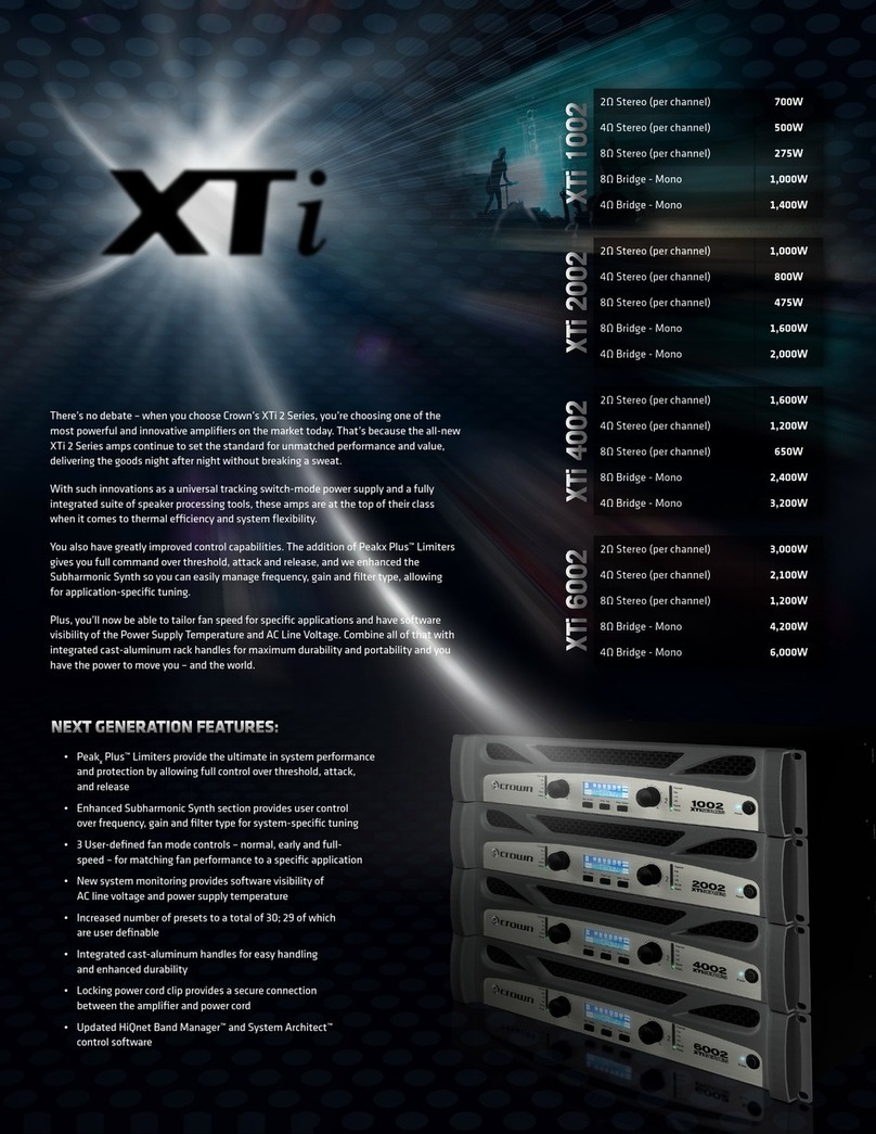
Output Connector Options
See these options under Output Connectors.
Specifications subject to change without prior notice. Latest
information available at www.crownaudio.com.
BCA, Crown and Crown Audio are registered trademarks of
Crown International. Other trademarks are the property of
their respective owners. Printed in U.S.A.
© 2006 Crown Audio®, Inc.
TNEMNGISSANIPTUTUO
HCNIPHCNIP
2+11+1
2–11–1
+22+2
–22–2
2-HC1-HC

Other manuals for ce 4000

5

Other Crown Amplifier manuals

Crown Micro-Tech MT-1200 User manual

Crown

Crown Micro-Tech MT-1200 User manual

Crown IC-150 User manual

Crown

Crown IC-150 User manual

Crown OC-150A Quick start guide

Crown

Crown OC-150A Quick start guide

Crown Macro-Tech MA-5000VZ User manual

Crown

Crown Macro-Tech MA-5000VZ User manual

Crown 1160MA User manual

Crown

Crown 1160MA User manual

Crown 1160A User manual

Crown

Crown 1160A User manual

Crown Studio Reference I User manual

Crown

Crown Studio Reference I User manual

Crown Com-Tech 210 User manual

Crown

Crown Com-Tech 210 User manual

Crown DCi 8|300 User manual

Crown

Crown DCi 8|300 User manual

Crown 1400 CSL User manual

Crown

Crown 1400 CSL User manual

Crown SL-2 Quick start guide

Crown

Crown SL-2 Quick start guide

Crown Micro-Tech MT-600 Manual

Crown

Crown Micro-Tech MT-600 Manual

Crown CE 2000 Manual

Crown

Crown CE 2000 Manual

Crown CE-1000 User manual

Crown

Crown CE-1000 User manual

Crown DC-300A II User manual

Crown

Crown DC-300A II User manual

Crown XTI2 SERIES XTI 4002 User manual

Crown

Crown XTI2 SERIES XTI 4002 User manual

Crown CROWN K Series User manual

Crown

Crown CROWN K Series User manual

Crown 135MA User manual

Crown

Crown 135MA User manual

Crown CTs 8200 USP/CN User manual

Crown

Crown CTs 8200 USP/CN User manual

Crown I-Tech I-T4000 User manual

Crown

Crown I-Tech I-T4000 User manual

Crown Macro-Tech MA-5002VZ User manual

Crown

Crown Macro-Tech MA-5002VZ User manual

Crown Vrack 4x3500 User manual

Crown

Crown Vrack 4x3500 User manual

Crown MRX-24 User manual

Crown

Crown MRX-24 User manual

Crown Macro-Tech 5000i User manual

Crown

Crown Macro-Tech 5000i User manual

Popular Amplifier manuals by other brands

Dynacord H 2500 owner's manual

Dynacord

Dynacord H 2500 owner's manual

Clarion XC1140 Owners manual and installation manual

Clarion

Clarion XC1140 Owners manual and installation manual

HumanTechnik PRO LOOP LOS Operation instructions

HumanTechnik

HumanTechnik PRO LOOP LOS Operation instructions

Phoenix Gold QX500.5 manual

Phoenix Gold

Phoenix Gold QX500.5 manual

Steren AMP-210SD instruction manual

Steren

Steren AMP-210SD instruction manual

McIntosh C26 owner's manual

McIntosh

McIntosh C26 owner's manual

Arylic Up2Stream Mini v2 user manual

Arylic

Arylic Up2Stream Mini v2 user manual

Goldmund MIMESIS 16 user manual

Goldmund

Goldmund MIMESIS 16 user manual

Yamaha MX-800 owner's manual

Yamaha

Yamaha MX-800 owner's manual

Altec Lansing 9444B POWER AMPLIFIER SERVICE Specifications

Altec Lansing

Altec Lansing 9444B POWER AMPLIFIER SERVICE Specifications

Toa VP-1061 operating instructions

Toa

Toa VP-1061 operating instructions

Denon AVP-8000 operating instructions

Denon

Denon AVP-8000 operating instructions

Roland GP-100 Service notes

Roland

Roland GP-100 Service notes

SoundDigital SD600.1D owner's manual

SoundDigital

SoundDigital SD600.1D owner's manual

LEGRAND ON-Q F7630 Instruction/installation sheet

LEGRAND

LEGRAND ON-Q F7630 Instruction/installation sheet

Seventh Circle Audio A12B quick start guide

Seventh Circle Audio

Seventh Circle Audio A12B quick start guide

Rotel RA-1570 Preliminary data sheet

Rotel

Rotel RA-1570 Preliminary data sheet

TRACE ELLIOT Elf owner's manual

TRACE ELLIOT

TRACE ELLIOT Elf owner's manual

manuals.online logo
manuals.online logoBrands
  • About & Mission
  • Contact us
  • Privacy Policy
  • Terms and Conditions

Copyright 2025 Manuals.Online. All Rights Reserved.