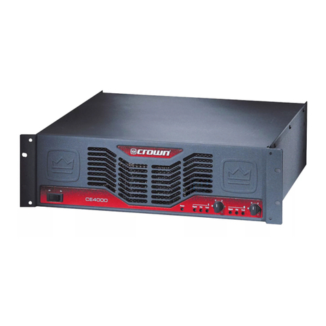
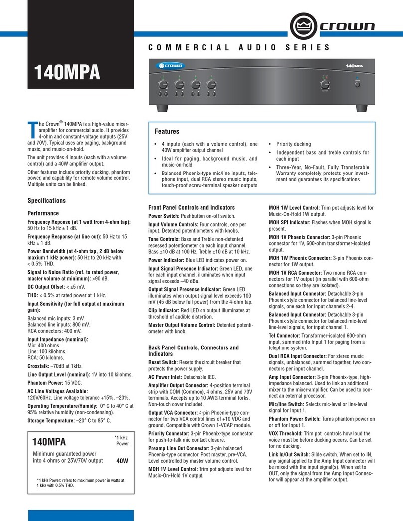
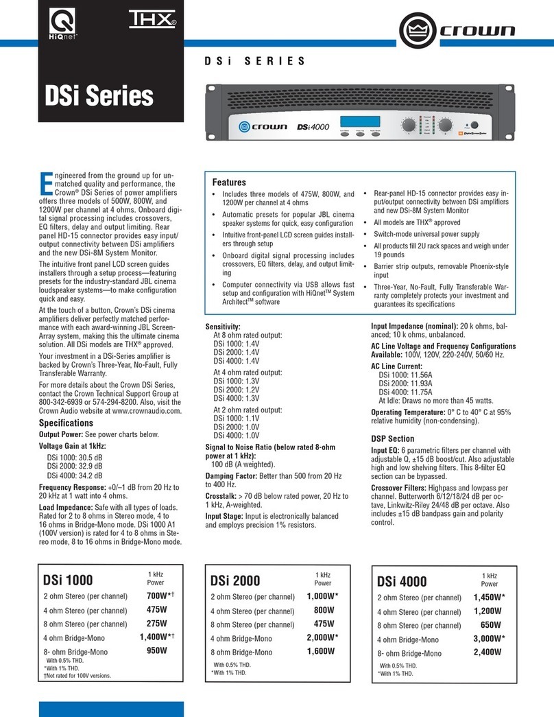
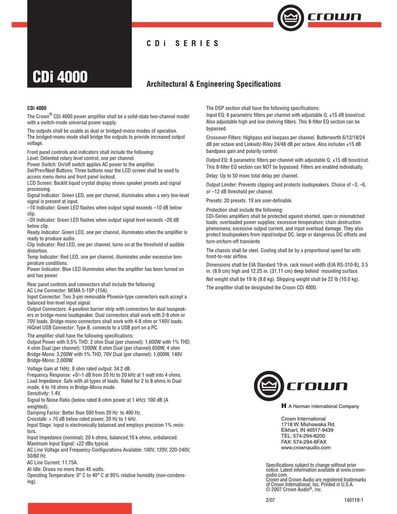
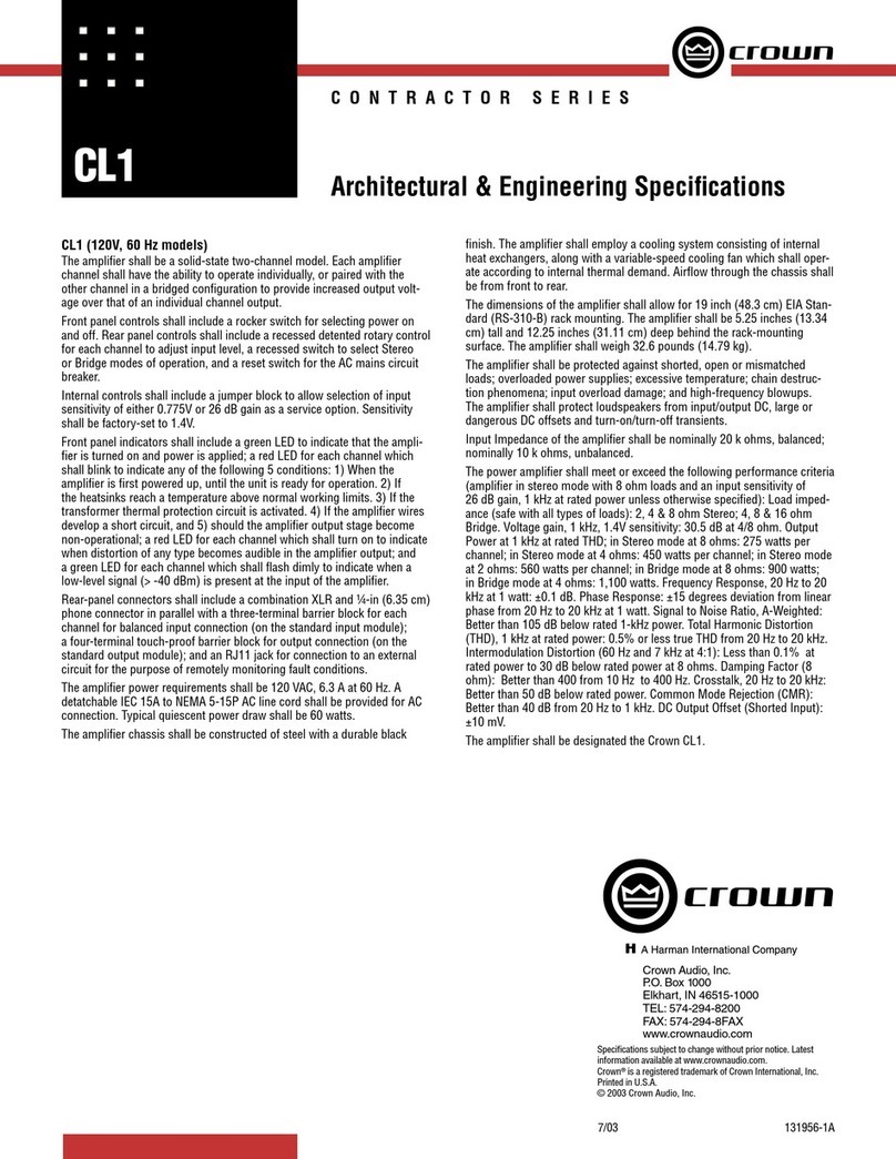
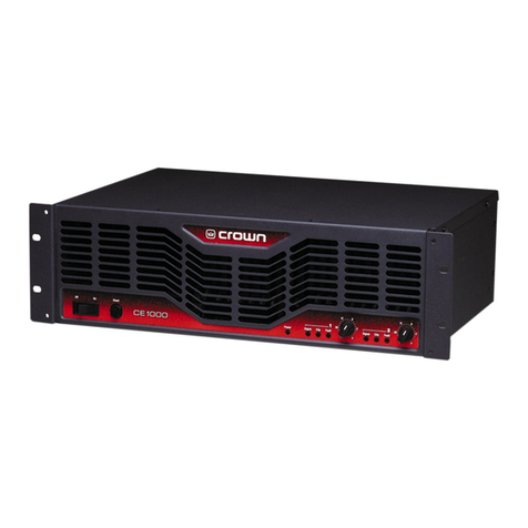
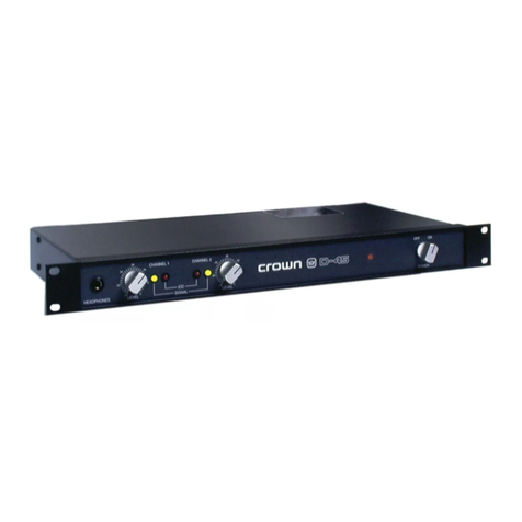
Crown CE Series User manual

125645-1
12/97
CE-Series
© 1997 by Crown International, Inc., P.O. Box 1000, Elkhart, IN 46515-1000
U.S.A. Telephone: 219-294-8000. Fax: 219-294-8329. Trademark Notice:
Crown
®is a registered trademark of Crown International, Inc. Other
trademarks are the property of their respective owners.

Page 2
CE-Series
Amps with an Attitude!
Da Rules
Da Rules
Hey! I'm Eric
Let me fill you
in about your
new CE-Series
Amp!!
3. WARNING: Shock
hazard. To reduce the
risk of fire or electric
shock, do not expose this
unit to rain or moisture.
Do not immerse your
CE-
Series
amplifier in any
liquid. Do not operate
your amplifier near a
pool, bathtub or other
standing water (even on
a dare).
4. Do not bypass or defeat
the grounding or
polarization means used
on the
CE-Series
amplifiers. Make sure all
blades on the polarized
power plug can be fully
inserted into the exten-
sion cord, receptacle or
other outlet that will be
used with the unit.
5. Your
CE-Series
amp
should be cleaned only
with a damp cloth
6. Take care of the power
cord attached to your
CE-
Series
amplifier. Avoid
situations where your
cord might be stretched,
pinched, or otherwise
abused. Route it to avoid
foot traffic. Pay special
attention to the cord
connector and attachment
points.
1. Read all safety and operating instructions
before operating the
CE-Series
amplifier.
Follow all instructions carefully and heed any
warnings given.
2. Do not drop or spill any foreign object or
liquid into the
CE-Series
amplifier.

Page 3
CE-Series
Amps with an Attitude!
7. Do not attempt to service
this unit beyond instructions
contained in this manual.
Refer all servicing to the
Crown Service Department.
8. Keep your
CE-Series
amplifier away from sources
of heat, such as a radiator or
oven. Do not cover or
surround your amp with
material which may retain
heat, such as a blanket or
curtain.
9. Obtain assistance
from qualified service
personnel if any of the
following occurs:
• The power cord or plug
has been damaged in
any way.
• Foreign objects or
liquid have fallen into
the amplifier enclosure.
• The amplifier has been
exposed to rain or has
been partially or totally
immersed in any liquid.
• The amplifier has been
dropped or the chassis
has been damaged.
• You notice a marked
change in performance,
or your
CE-Series
amp
does not appear to
operate normally.
Lightning Bolt Symbol:
This symbol is used to alert the
user to the presence of dangerous
voltages and the possible risk of
electric shock.
Exclamation Mark Symbol:
This symbol is used to alert the
user to make special note of
important operating or maintenance
instructions found in the reference
manual.
Watch for these symbols:
Keep these
instructions
where you can
look at em
later!
10. CAUTION: Do not locate
sensitive, high-gain
equipment such as
preamplifiers or tape
decks directly above or
below the unit. If an
equipment rack is used,
we recommend locating
the amplifier(s) in the
bottom of the rack and
the preamplifier or other
sensitive equipment at
the top.

Page 4
CE-Series
Amps with an Attitude!
Unpacking Your
CE-Series Amp
Please unpack and inspect your amplifier for any damage that
may have occurred during transit. If damage is found, notify
the transportation company immediately. Only you can initiate
a claim for shipping damage. Crown will be happy to help as
needed. Save the shipping carton as evidence of damage for
the shipper’s inspection.
We also recommend that you save all packing materials so
you will have them if you ever need to transport the unit.
NEVER SHIPTHE UNITWITHOUTTHE FACTORY PACK.

Page 5
CE-Series
Amps with an Attitude!

Page 6
CE-Series
Amps with an Attitude!
Quick Start!
You’ve waited a long time for this! We know you just can’t wait
to crank up your new Crown®
CE-Series
amplifier. And you
suredon’twant to flipthroughpages of tech-talk just to findout
where the “ON” switch is. So that’s why we provided you with
this quick and simple page to get you up and running right
away. Just take a few minutes to read through this—no more
than five or ten, max—you’ll be glad you did.
1. Make sure the
CE-Series
amp and all other equipment is
turned OFF before you begin wiring. By the way, the amp
power switch is located on the far left side of the front
panel. It is OFF when depressed on the left.
2. Mount your
CE-Series
amp securely in the rack, or posi-
tion it on a solid surface.
3. Connect the left and right inputs coming from your mixer,
preamp, or processor. You can use either balanced 1/4-inch
phone, 3-pin XLR or barrier block connectors. You can also
choose to run in MONO mode. (See Figures 2.6 and 2.8.)
4. Connect the output wiring (left and right speakers). You
will need two (2) Neutrik Speakon®NL4FC mating con-
nectors.
5. Connect your
CE-Series
amp and other equipment to the
appropriate power source.
6. Turn on your mixer, preamp, signal processor, or any
other equipment in your system EXCEPT your
CE-Series
amplifier. (Remember: the best is worth waiting for.)
7. Make sure the Channel 1 and Channel 2 level (volume)
controls on your
CE-Series
amplifier are turned all the way
down (counter-clockwise), then flip the power switch ON.
Note: The Fault light blinks a few times, and the “Power”
light will glow a bright green to indicate power is on.
8. (Now comes the fun!) Supply input, adjust amp levels
and enjoy.
9. You can check the green signal light to verify input, if nec-
essary.
Did You Remember To
Page 7
CE-Series
Amps with an Attitude!
CAUTION: Excessive outputlevels maytoast yourspeak-
ers. Crown’s
CE-Series
amplifiers have such low distor-
tion, you may not realize the actual level being reached
until it’s too late. Please exercise caution and drive your
speakers responsibly (or at least warn your neighbors!).
oGet Your Speakons®?
Typical Stereo
Hookup

Page 8
CE-Series
Amps with an Attitude!
Contents
Da Rules ............................................................... 2
Unpacking Your
CE-Series
Amplifier ..................... 4
Features................................................................ 5
Quick Start ............................................................ 6
1 Welcome............................................................. 10
2 Detailed Install .................................................... 14
3 Operation............................................................ 27
4 Other Issues:
Balancing the Line .............................................. 31
The Dastardly Duo: Hum and Buzz ..................... 32
5 Advanced Features and Options:
Crown SST Modules............................................ 35
Fault Monitoring .................................................. 38
Handle Kit ........................................................... 38
Tamper-Resistant Hole Plugs............................... 39
6 Principles of Operation........................................ 40
7 Specifications ..................................................... 44
8 Service................................................................ 48

Page 9
CE-Series
Amps with an Attitude!
Illustrations
Typical Stereo Hookup .......................................... 7
1.1 The
CE-Series
Amplifier ................................. 10-11
1.2 The Big Picture: Controls, Indicators and
Connectors ................................................... 12-13
2.1 Mounting Dimensions.......................................... 14
2.2 Mode Switch ....................................................... 15
2.3 Input Sensitivity Switch........................................ 15
2.4 Typical Input Wiring............................................. 16
2.5 Neutrik Speakon®NL4FC Assembly Order.......... 17
2.6 Neutrik Speakon®NL4FC Wiring ......................... 18
2.7 Stereo Output Wiring ........................................... 18
2.8 Bridge-Mono Output Wiring................................. 19
2.9 Neutrik NL4FC Insert into Housing ...................... 19
2.10 Stereo Hookup ............................................... 20-21
2.11 Bridge-Mono Hookup..................................... 22-23
2.12 Neutrik NL4FC Chuck into Housing ..................... 24
2.13 Neutrik NL4FC Bushing onto Housing ................. 25
3.1 Front Panel Indicators & Controls ........................ 28
3.2 Back Panel Controls............................................ 29
4.1 Balanced & Unbalanced Input Wiring ................. 31
4.2 Polarity Conversions............................................ 31
4.3 Balanced Input Wiring......................................... 33
4.4 Unbalanced Input Wiring .................................... 34
5.1 Block Diagram for Crown’s Crossover SST ..... 36-37
5.2 Fault Status LED Circuitry.................................... 38
5.3 RJ Jack Wiring and Pin Assignments .................. 38
5.4 Tamper-Resistant Hole Plugs............................... 39
6.1
CE-Series
Amplifier Block Diagram ................ 40-41
7.1 Output Pin Assignments...................................... 46
7.2 Awesome Frequency (Amplitude) Response....... 47

Page 10
CE-Series
Amps with an Attitude!
Thanks for buying this
CE-Series
amplifier. Here at Crown, we
appreciate your support, and we think you’ll find that you’ve
also done yourself a favor by choosing Crown. That’s because
the
CE-Series
amps are REAL Crown amplifiers, designed by
dedicated Crown engineers to fit your needs AND your wallet.
Yes, these Crown engineering dudes, cool guys that they are,
thoughtthat no-oneshouldbewithoutthat greatCrownsound.
So what if you’re not running a pro tour (yet)? You deserve the
best in amplified sound. And the best, of course, is still Crown.
(My dad always said, it ain’t braggin’ if it’s true.)
TheengineersatCrowngot together and thumbed their noses
at those high-ranking corporate types who always want big
stickers and huge markups. What they came up with is the
CE-Series
of amplifiers. We think you’ll really like it.
So what else is special about the
CE-Series
?
First off, your
CE-Series
amplifier features all front-panel con-
trols for ease of use. But—so you don’t have to sacrifice secu-
rity for comfort—the front panel level controls can be set, then
removed entirely from the panel. Whether for long-term control
in a fixed installation or short-term protection against unautho-
rized adjustments, this feature allows you to just set-and-for-
get your level controls.
Welcome

Page 11
CE-Series
Amps with an Attitude!
Fig. 1.1
The CE-Series
Amplifier
Your
CE-Series
amp also comes with a standard SST module
(System Solution Topologies) that gives you the choice of bar-
rier strip, 1/4-inch phone, or 3-pin XLR connectors and works
great in most situations. However, if you’re using your CE amp
for theater applications, or if you have other special input
needs, you can pull the standard SST module and simply plug
in one of our advanced SST modules, (such as our electronic
crossover).
Don’t forget the impressive output. The CE 1000 produces an
awesome 1,100 watts, while the CE 2000 pumps out 1,975
watts of power.* For output connectors, the
CE-Series
features
genuine Neutrik Speakon®4-pole connectors for quick, se-
cure and safe connections.
And, of course, there’s no mistaking a
CE-Series
amp. Its rugged
lookwillimpressyourfriends almostasmuchasthe Crownname.
This manual will help you correctly set up and use your new
amplifier—we strongly recommend you read all instructions,
warnings and cautions. Also, for your protection, please send
in your warranty registration card today. And save your bill of
sale—it’s your ofof
ofof
official prficial pr
ficial prficial pr
ficial proof of puroof of pur
oof of puroof of pur
oof of purchase.chase.
chase.chase.
chase.
* 1,100 watts and 1,950 watts total in bridge-mono at 4 ohms (for the CE
1000 and CE 2000 respectively), 560 watts and 975 watts per channel at 2
ohms. See the Specifications Section for details.

Page 12
CE-Series
Amps with an Attitude!
Fig. 1.2
The Big
Picture:
Controls,
Indicators &
Connectors

Page 13
CE-Series
Amps with an Attitude!

Page 14
CE-Series
Amps with an Attitude!
2 Detailed Install
Follow these instructions for a detailed explanation of
CE-Se-
ries
installation procedures and options. If you just want to get
up and running as quickly as possible, see the Quick Start
section on page 6.
2.1—Begin with the amplifier turned off and disconnected
from the power receptacle. The
CE-Series
power switch
is located on the left side of the front panel; it is OFF when
depressed on the left. Equipment that will be connected
to the inputs of the amplifier (such as mixers,equalizers or
signal processors) should also be turned off.
2.2—Mount the amplifier. Your
CE-Series
amp can be
mounted in a standard, 19-inch (48.3-cm) equipment
rack, or it can be simply stacked with other equipment.
And since your
CE-Series
amp is not as deep as many
amplifiers (only 12.25 inches (31.11 cm) behind the front
panel), you can also mount it in the shallow, wall-mount
racks.
Fig. 2.1
Mounting
Dimensions
If you choose to mount your amp in a rack, you should
secure the back of the rack as well as the front. Securing
the amp at both front and rear will assure that the amp
stays in place, even when the rack is transported or acci-
dentally dropped (which we know never happens).

Page 15
CE-Series
Amps with an Attitude!
2.3—Set the mode switch. Turn off the amplifier before mov-
ing this switch. The Mode switch should be in the “Stereo”
position when you’re running in Stereo Mode. Stereo
Mode allows independent inputs on the left and right
channels to feed separate speakers at the output. It’s the
configuration typically chosen (by 90% of left-handed
musicians) for everyday audio applications.
Fig. 2.2
Mode Switch
Fig. 2.3
Input
Sensitivity
Switch
Turn the Mode switch to “Bridge-Mono” to have a single
input that feeds to a single output with twice the voltage
of Stereo Mode.Usethisconfigurationifyouwantto giveup
stereo capabilities in order to drive your speakers
louder.
(note that the wiring will also need to be changed for this
configuration—see step 6 later in this section).
2.4—Set the Input Sensitivity switch to the desired setting.
Two choices are available: 1.4 V for full rated (8-ohm) out-
put, or a fixed voltage gain of 26 dB. (The
CE-Series
ship
from the factory with default settings of 1.4 V, which trans-
lates to approximately 33 dB of gain.) Refer to the infor-
mation on “Input Sensitivity” in the Operation section
(section 3) for detailed information.

Page 16
CE-Series
Amps with an Attitude!
2.5—Connect the inputs of the
CE-Series
amp to your mixer,
equalizers, or signal processors ahead of the amp. Three
types of balanced input connectors are provided, allow-
ing you to choose barrier strip, 1/4-inch phone or 3-pin
XLR connectors. You can also choose to use either bal-
anced or unbalanced wiring. (See the information on
“Balancing the Line” in the Other Issues section for an
explanation of balanced vs. unbalanced wiring.)
If the Mode switch is in “Bridge-Mono” position, only the
Channel 1 input connectors should be used.
Fig. 2.4
Typical Input
Wiring
Input Wiring Tips
1. For all input connectivity, use shielded wire only. Cables with a foil
wrap shield or a high-density braid are superior. Cables with a
stranded spiral shield, although very flexible, will break down over
time and cause noise problems.
2. Try to avoid using unbalanced lines with professional equipment. If
you have no choice, keep the cables as short as possible. (Refer to
the information on “Balancing the Line” in the Other Issues section.)
3. To minimize hum and crosstalk, avoid running low-level input, high-level output and AC
power feeds in the same path. Try to run differing signal paths at 90° to one another. If you
must use a common path for all cables, use a star-quad cable for the low-level signals.
4. When changing input connectors or wiring, turn the amplifier level controls all the way
down (counter-clockwise) before connecting or disconnecting input plugs.
5. When changing output connections, a professional dude will turn the amplifier level down
and the AC power off to minimize the chance of short-circuiting the output.

Page 17
CE-Series
Amps with an Attitude!
2.6——
——
—Connect the outputs
of the
CE-Series
amp to your
loudspeakers. You will need two (2) Neutrik Speakon®
NL4FC connectors to interface with this amplifier.* You will
also need high-quality two- or four-conductor speaker
cable with the appropriate end-connectors to fit the in-
puts on your speakers, a pair of needle-nosed pliers and a
1.5-mm hex key to assemble the Speakon connectors.
To assemble the Neutrik Speakon NL4FC connector,
complete the following steps:
2.6.1—Slide the bushing(E)and chuck (D) onto theendof the
cable as shown (Figure 2.5).**
Fig. 2.5
Order of
Assembly for
the Neutrik
Speakon
NL4FC
Connector
2.6.2—Strip approximately 3/4-inch (19-mm) of casing from
the cable end. Strip approximately 1/4-inch (6-mm) from
the end of each of the conductors down to bare wire.
2.6.3—Slide the end sleeves (C) onto the wire ends and crimp
in place.
2.6.4—Insert each wire with end sleeve into the top of appro-
* You can purchase the Speakon®NL4FC connectors from your local dealer,
or contact NEUTRIK AG, Im alten riet 34, Schaan FL-9494, Furstentum
Liechtenstein, 011-41-75-237-2424, FAX 011-41-75-232-5393,
www.neutrik.com or Neutrik USA, Inc., 195 Lehigh Ave., Lakewood, NJ
08701-4527, (908) 901-9488, Fax (908) 901-9608, www.neutrikusa.com or
Crown International, Inc., 1718 West Mishawaka Road, Elkhart, IN 46517-
4095, USA, 219-294-8000, FAX 219-294-8329, www.crownaudio.com.
** Your NL4FC connector kit should contain both a black and a white chuck.
Use the white chuck for cable with a diameter of 0.25- to 0.5-inch (6.35- to
12.7 mm). Use the black chuck for cable with a diameter of 0.375- to 0.625-
inch (9.525- to 15.875-mm).

Page 18
CE-Series
Amps with an Attitude!
priate slot of the connector insert (B) as shown in Figure
2.6. Use a 1.5-mm hex key inserted into each side slot to
tighten the connection.
2.6.4a—If the Mode switch is in the “Stereo” position (for
stereo configuration),
connect the positive (+) and nega-
tive (–) leads of each wire to the appropriate Channel 1
and Channel 2 connectors as shown in Figure 2.7. Refer
to Figure 2.10 for complete system setup. You may use all
4 poles of the Channel 1 output connector to feed both
speakers, if you wish.
Fig. 2.7
Stereo Output
Wiring
Fig. 2.6
Wiring for
the Neutrik
Speakon
NL4FC
Connector

Page 19
CE-Series
Amps with an Attitude!
2.6.4b—If the Mode switch is in the “Bridge” position (for
mono configuration), connect the load across the positive
(+) terminals of the connector as shown in Figure 2.8. Re-
fer to Figure 2.11 for complete system setup. For Bridge-
Mono Mode, non-inverting output, Ch1+ is the positive
(+) and Ch2+ is the negative (–).
2.6.4c—Never short or parallel the output channels of a
CE-Series
amplifier to itself or any other amplifier.
Fig. 2.8
Bridge-Mono
Output Wiring
2.6.5—Slide the connector insert (B) into the connector hous-
ing (A), making sure that the large notch on the outer
edge of the insert lines up with the large groove on the
inside of the connector housing. The insert should slide
easily through the housing and out the other side until it
extends approximately 3/4-inch (19-mm) from the end of
the housing (see Figure 2.9).
Fig. 2.9
Detailed Neutrik
Speakon NL4FC
Connector
Assembly: Insert
into Connector
Housing

Page 20
CE-Series
Amps with an Attitude!
Other manuals for CE Series
1
This manual suits for next models
2
Table of contents
Other Crown Amplifier manuals

Crown
Crown 180MA User manual

Crown
Crown DSi 2000 User manual

Crown
Crown COMMERCIAL AUDIO 160MA User manual

Crown
Crown Xs Series User manual

Crown
Crown Power Base-2 Quick start guide

Crown
Crown PL-3 User manual

Crown
Crown CH1 User manual

Crown
Crown CTs 600 User manual

Crown
Crown SA-2 User manual

Crown
Crown Macro-Tech 12000i User manual