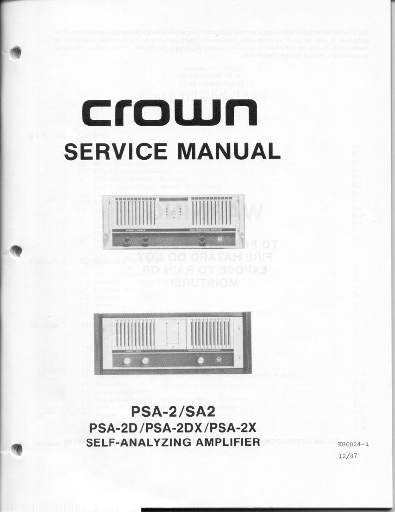
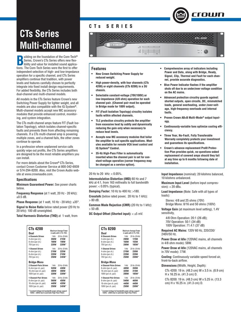
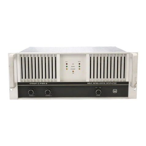
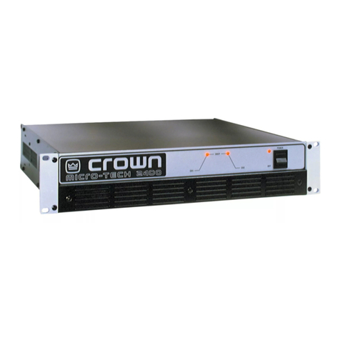
Crown PSA-2 User manual

crown
SERVICE
MANUAL
PSA-2/SA2
PSA-2D
/PSA-2DX/PSA-2X
SELF-ANALYZING
AMPLIFIER)
=
xcsoo2
“1

The
information
furnished
in
this
manual
does
not
include
all
of
the
details
of
design,
production,
or
variations
of
the
equipment.
It
does
not
cover
all
the
possible
contingencies
which
may
arise
during
operation,
installation,
or
maintenance.
Should
special
problems
arise,
or
further
information
be
desired,
please
contact
the
Crown
International
Customer
Services
Department.
Crown
International
1718
W.
Mishawaka
Rd.
Elkhart,
Indiana
46514
Ph:
(219)
294-5571
WARNING
TO
PREVENT
SHOCK
OR
FIRE
HAZARD
DO
NOT
EXPOSE
TO
RAIN
OR
MOISTURE!
CROWN
INTERNATIONAL,
INC.
1718
W.
MISHAWAKA
RD.
ELKHART,
INDIANA
46514

RVW
Sec.
™
Section
6
Section
7
Section
8
™
Review
re
Introduction
.
Il.
Warranty
...
Ill.
PSA-2
Specifications
.
XI
Illustrated
Parts
List
crown
TABLE
OF
CONTENTS
PSA-2
Stereo
Specifications
PSA-2
Monaural
Specifications
.
PSA-2
Balanced
Input
Module
Specifications
SA2
Specifications
.....
SA2
Stereo
Specification:
SA2
Monaural
Specifications
.
Panel
Configuration
(PSA-2)
.
Panel
Configuration
(SA2)
.
PSA-2
Available
Formats
Performance
Graphs
...
Gr
GETeray
formations
s..
22
22
aa
sre
csisate
Pleas
elas
ate
OCIS
Fink
99
sales
Soletgiel
es
discaretertw
ols
6.2
Standard
and
Special
Parts
..
6.3
Ordering
Parts
.
6.4
Shipment
......
Qs
RMN
IUSs
gere's'n
cigie
stile
sats
Latte
cue
edie
sels
6.6
Schematics/Bd.
Layouts/
Parts
Lists/
Exploded
View
Drawings
...
Maintenance
7.1
Introduction
7.2.
Required
Test
Equipment
7.3.
Soldering
Techniques
7.4
Basic
Troubleshooting
7.5
Discharging
Instructions
.
7.6
Disassembly
for
Inspection,
Service,
Testing,
Adjustment
and
Repairs
.
7.7
Reassembly
7.8
Repair
Instructions.
7.9
Electrical
Checkout,
Troubleshooting
and
Adjustment
.
7.10
PSA-2
HI/LO
Pass
Filter
Frequency
Alterations.
7.11
Voltage
Conversion
Instructions
.
7.12
Block
Diagram
Circuit
Theory
7.13
Theory
of
Operation
Service
Bulletins
..

crown
LIST
OF
ILLUSTRATIONS
PSA-2:Front
Panel
.5--ciaes.csess
de
sao
HME
aes
CONT
Re
Ml
iss
Sara
+
os
oles
SHES
PSA-2
Back
Panel
..
SA2
Front Panel
.
SA2
Back
Panel
..
PSA-2
Available
Formats.
Typical
IM
Distortion.
.
Typical
Output
Impedance
.
.
Typical
Frequency
Response
.
Output
Phase
Response
Typical
Damping
Factor
(8
ohms)
.
Typical
Crosstalk
........
Typical
Noise
Spectrum.
oi
Typical
CMR
Through
Balanced
Input
Module
Typical
Power
Output
Low
Frequency
Protect
Action
Typical
Frequency
Response
-
Balanced
Input
Module
.
Typical
AGC
Action
Relay/
Power
Supply
Module
Schematic
. .
Relay
Module
Component
Board
Layout
Low
Voltage
Power
Supply
Component
Board
Layout
.
Anti-pop
Module
Schematic
........
Anti-pop
Module
Foil
Board
Layout
.
Anti-pop
Module
Component
Board
Layout
.
Main
Module
#1/Output
Terminal/
PNP-NPN
§
Main
Module
#2/Output
Terminal/
PNP-NPN
Schematics
Main
Module
#1
Component
Board
Layout
Main
Module
#2
Component
Board
Layout
PNP
Output
Module
Component
Board
Layout
.
NPN
Output
Module
Component
Board
Layout...
Output
Terminal
Module
Component
Board
Layout
.
Mother
Board
Module
Component
Board
Layout
.
PSA-2
Input
Connector
Module
Schematic
..
PSA-2
Input
Connector
Module
Component
Board
Layout
SA2
Input
Connector
Module
Schematic
SA2
Input
Connector
Module
Component
Board
Layout
..
PSA-2
Display
Module
Schematic
........
PSA-2
Display
Module
Foil
Board
Layout.
PSA-2
Display
Module
Component
Board
Layout
.
SA2
Display
Module
Schematic
........
SA2
Display
Module
Foil
Board
Layout.
SA2
Display
Module
Component
Board
Layout
.
PSA-2
B.I.M./
Filter
Board
Schematic
Balanced
Input
Module
Foil
Board
Layout
Balanced
Input
Module
Component
Board
Layout.
Filter
Board
Component
Layout
Front Panel
Assembly.
.
SA2
Front
Panel

Fig.
Fig.
Fig.
Fig.
Fig.
Fig.
Fig.
Fig.
Fig.
Fig.
Fig.
Fig.
Fig.
Fig.
Fig.
Fig.
Fig.
Fig.
Fig.
Fig.
Fig.
Fig.
Fig.
Fig.
Fig.
Fig.
Fig.
Fig.
Fig.
Fig.
Fig.
Fig.
Fig.
Fig.
Fig.
Fig.
Fig.
Fig.
Fig.
Fig.
Main
Chassis
Assembly
.
.
Transformer
Assembly
...
Power
Capacitor
Assembly
.
NPN/PNP
Output
Assembly
.
Back
Panel
Assembly
Final
Assembly
PSA-2
Balanced
Input
Module
Assembly
.
Miniature
Soldering
Iron
.........
Correct
and
Incorrect
Solder
Applica
Unsoldered
Wire
...
External
Strands
...
Cut
Strands....
Wire
Strippers
.
Disturbed
Joints
.
.
Cold
Solder
Joint.
Rosin
Joint
....
:
Component
Lead
Spacing
.
Component
Lead
Bending
.
Correct
Pressure
Applied
..
Acceptable
Solder
Joints
.
Soldering
to
a
Lug
Turret
Terminal
..
Wire
Braid
Desoldering
..
Discharge
Points
......
Component
Location
Diagram
.
Internal
Hard
Wiring
Diagram
.
Consumable
Materials
Chart
...
Correct
Output
Waveform
............-
Correct
Square
Wave
Output
Waveform.
Mono
Output
Waveform
IM
Distortion
Test
Set-up
...
Signal
to
Noise
Test
Set-up
Test-tone
Output
Waveform
.
Filter
Board
Schematic
......
Filter
Board
Component
Layout.
Voltage
Conversion
.......
World-wide
Voltage
Map
PSA-2/SA2
Block
Diagram
Common
Output
Configuration
...
PSA-2/SA2
Output
Configuration
.

crown
REVIEW
SECTION
I.
Introduction
This
manual
contains
complete
service
information
on
the
Crown
PSA-2/SA2/PSA-2D/PSA-2DX/
PSA-2X
amplifiers.
It
is
designed
to
be
used
in
conjunction
with
the
PSA-2/SA2
Instruction
Manual.
However,
some
important
information
is
duplicated
in
this
Service
Manual
in
case
the
Instruction
Manuals
are
not
readily
available.
NOT
THE
INFORMATION
IN
THIS
MANUAL
IS
INTENDED
FOR
USE
BY
AN
EXPERIENCED
TECHNICIAN
ONLY!
II.
As
a
Crown
Warranty
Service
Station,
you
should
be
familiar
with
Crown
warranty
policies.
Each
Instruction
Manual
contains
basic
policies
as
related
to
the
customer.
However,
under
questionable
circumstances,
please
contact
the
Technical
Service
Department
or
Director
of
Customer
Service
at:
Crown
International,
Inc.,
1718
W.
Mishawaka
Road,
Elkhart,
IN
46514.
Warranty
Hl.
General
Protection:
Protection
circuitry
limits
the
output
level
to
protect
the
output
transistor
stage,
even
in
the
case
of
elevated
temperature.
Transformer
overheating
results
in
shutdown
(STANDBY)
of
that
particular
channel.
Controlled
slewing
rate
voltage
amplifiers
protect
the
unit
against
RF
burnouts.
Input
overload
protection
is
furnished
by
a
resistor
at
the
input
of
the
amplifier
to
limit
current.
PSA-2
Specifications
DC
Output
Offset:
(Shorted
input)
+10
millivolts.
Phase
Response:
+0,
-15
degrees
DC-20KHz
at
I
watt.
Input
Impedance:
(XLR
balanced)
20K
ohms.
(phone
jack
unbalanced)
25K
ohms
+30%.
High
Voltage
Power
Supply:
Two
800VA
transformers
with
computer
grade
capacitors
powered
through
10A
relays.
Low
Voltage
Power
Supply:
+15V
DC
supplies
are
provided
by
a
current
limited
shortproof
regulator.
Power
Requirements:
50-60Hz
AC
with
adjustable
taps
for
100,
120,
200,
220,
and
240
+10%
operation.
Draws
90
watts
or
less
on
idle
800W
at
250W
channel
output
into
8
ohms.
Turn
On:
May
be
switch
selected
for
instantaneous
or
four
second
delay
after
applying
power.
No
dangerous
transients.
Low
Frequency
Load
Protect.:
May
be
switch
selected
to
produce
shutdown
(STANDBY)
of
high
voltage
power
supply
for
DC
outputs
greater
than
26V
or
low
frequency
outputs
greater
than
26V
at
5Hz
(see
Graph
RVW.15).
Controls:
Two
position
ON/OFF
rotary
switch.
Ch.
|
and
Ch,
2
input
level
controls.
The
LOW
FREQ
PROTECT,
DELAY
and
STEREO/
MONO
slide
switches
are
located
on
the
rear
panel.
Displays:
A
yellow
LED
indicates
STANDBY
mode
activated
for
that
respective
channel.
A
pair
of
green
LED's
indicate
SIGNAL
presence
at
the
output
of
that
respective
channel.
A
pair
of
red
LED's
(IOC)
indicate
amplifier
OVERLOAD
conditions
for
that
respective
channel.
An
amber
LED
POWER
indicator
driven
by
low
power
control
supply.
Connectors:
Unbalanced
Input
-
4”
phone
jacks.
Output-color
coded
dual
binding
posts
on
standard
%4”
centers;
spaced
%”
apart
for
mono
(balanced)
output
connection.
AC
Line
-
Three
wire
20A,
120V
male
connector
with
5
ft.
cable.
Ground
Selectivity
-
2
lug
terminal
block
with
removable
shorting
strap.
Module
Plug-ins:
Standard
rear-panel
balanced
input
module
(module
replacement
information
available
upon
request).

Dimensions:
19”
standard
rack
mount
(EIA
Standard
RS-310-B)
7”
height,
1434”
behind
mounting
surface.
Handles
extend
2'4”
in
front
of
mounting
surface.
Center
of
gravity
is
5.4”
behind
the
front
panel.
Weight:
57
pounds
(25.8Kg)
net
weight.
Finish:
Satinized
aluminum
front
panel
with
gray
suede
Lexan
insert
and
black
adonized
aluminum
chassis
and
covers.
Construction:
Aluminum
chassis,
specially
designed
“flow-through”
ventalation
top
front
and
side
panels.
Heavy
duty
handles
to
ease
transport.
Plug
in
rear
panel
balanced
input
module.
Heat
Sinking:
Forced
air
with
high
efficiency
coolers.
A
two
speed
fan
with
an
intake
filter
(washable)
mounted
on
the
back
(rear)
of
the
amplifier
forces
air
through
coolers
and
out
both
the
top
and
sides
of
the
amplifier.
IV.
PSA-2
Stereo
Specifications
(Exclusive
of
Balanced
Input
Module)
Output
Power:
220
watts
per
channel
minimum
RMS
(both
channels
operating)
into
an
8
ohm
load,
20Hz-
20KHz
at
a
rated
RMS
sum
total
harmonic
distortion
of
0.05%
of
the
fundamental
output
voltage
(tested
per
FTC
specifications),
250
watts
+IdB
per
channel,
20Hz-
20K
Hz
into
8
ohms
with
no
more
than
1.0%
THD
(EIA
Std.
SE-101-A).
Output
Power
(4
ohms):
400
watts
+1dB
per
channel,
20Hz-20K
Hz
into
4
ohms
with
no
more
than
1.0%
THD
(EIA
Std.
SE
101-A).
Output
Power
(2
ohms):
685
watts
+1dB
at
IK
Hz
per
channel
into
2
ohms
with
no
more
than
1.0%
THD.
Hum
and
Noise:
|
15dB
below
rated
output
“A”
weighted
110dB
below
rated
output
(20Hz-20K
Hz).
Response:
+
0.1dB
20Hz-20K
Hz
at
|
watt
into
8
ohms
+0
-
1,5dB
DC-80K
Hz.
Harmonic
Distortion:
Less
than
0.002%
from
20Hz-
1KHz
and
increasing
linearly
to
0.05%
at
20K
Hz
at
220
watts
into
8
ohms,
per
channel.
IM
Distortion:
Less
than
0.01%
from
0.25
watts
to
220
watts
into
8
ohms
per
channel.
Slewing
Rate:
Greater
than
30
volts
per
microsecond.
Damping
Factor:
Greater
than
700,
DC
to
400Hz
into
8
ohms.
Output
Impedance:
Less
than
12
milliohms
in
series
with
less
than
1,2
microhenries.
Load
Impedance:
Rated
for
16,
8,
and
4
ohm
usage,
safe
with
all
loads.
Voltage
Gain:
20+2%
or
26dB
+.2dB
at
maximum
gain.
Input
Sensitivity:
2.1
volts
for
220
watts
into
8
ohms.
Output
Signal:
Unbalanced,
dual
channel.
V.
PSA-2
Monaural
Specifications
(Exclusive
of
Balanced
Input
Module)
Output
Power
(8
ohms):
800
watts
+
1dB;
20Hz-20K
Hz
into
8
ohms
with
no
more
than
1.0%
THD
(EIA
std.
SEIOI-A).
Output
Power
(16
ohms):
500
watts
+
1dB;
20Hz-20K
Hz
into
16
ohms
with
no
more
than
1.0%
THD
(EIA
Std.
SE-101-A).
Output
Power
(4
ohms):
1370
watts
+1dBat
IK
Hzinto4
ohms
with
no
more
than
1.0%
THD.
Frequency
Response:
+0.2dB,
DC-20K
Hz
at
|
watt
into
16
ohms.
Harmonic
Distortion:
Less
than
0.003%
from
20Hz
to
IKHz
and
increasing
linearly
to
0.08%
at
20KHz,
500
watts
into
16
ohms.
Less
than
0.005%
from
20Hz
to
1KHz
and
increasingly
linearly
to
0.12%
at
20K
Hz,
800
watts
into
8
ohms.
IM
Distortion:
Less
than
0.015%
from
0.25
watts
to
500
watts
into
16
ohms.
Less
than
0.015%
from
0.25
watts
to
700
watts
into
8
ohms.
Slewing
Rate:
Gre
:
than
60
volts
per
microsecond,
Damping
Factor:
Greater
than
700,
DC-400Hz
into
16
ohms.
Output
Impedance:
Less
than
24
milliohms
in
series
with
less
than
2.4
microhenries.
Load
Impedance:
Rated
for
16
and
8
ohm
usage,
safe
with
all
loads.
Voltage
Gain:
40
+2
or
32dB+.2dB
at
maximum
gain,
Input
Sensitivity:
2.2
volts
for
500
watts
into
16
ohms.
Output
Signal:
Balanced,
single
channel.
Channel
|
controls
are
active;
Channel
2
inactive
but
not
removed
from
operation.
VI.
PSA-2
Balanced
Input
Module
Specifications
Controls:
Channel
|
and
Channel
2
input
gain
adjust
with
the
AGC
Threshold,
is
accessible
from
the
rear
on
the
Balanced
Input
Module.
Hum
and
Noise:
-85dBm
equivalent
input
noise
20Hz-
20K
Hz,
600
ohm
source,
gain
set
at
unity.

crown
Frequency
Response:
Flat
+0.2dB
20Hz
to
20KHz.
High
and
Low
Pass
Filters:
3
pole
Butterworth
18dB/octave;
SOHz
and
1S5KHz
standard
frequencies.
(Other
roll-off
points
available;
see
Sec.
7.10
for
details.)
Slide
switch
activated.
Compressor
Action:
Range
of
compression
restricted
to
13d
B
by
design
(wider
range
would
aggravate
feedback
in
live
performance).
Threshold
adjustable
from
overload
level
of
main
amplifier
to
12dB
lower.
Balanced
Input
Voltage
Gain:
Variable
0-10
+30%.
Test
Tone:
Switch
activated
wide
spectrum
50Hz-20K
Hz
tone.
Common
Mode
Rejection:
70dB
5SHZ-3KHz
55dB
20K
Hz
(see
Graph
RVW.13).
VII.
SA2
Specifications
General
Protection:
Protection
circuitry
limits
the
output
level
to
protect
the
output
transistor
stage,
even
in
the
case
of
elevated
temperature.
Transformer
overheating
results
in
shutdown
(STANDBY)
of
that
particular
channel.
Controlled
slewing
rate
voltage
amplifiers
protect
the
unit
against
RF
burnouts.
Input
overload
protection
is
furnished
by
a
resistor
at
the
input
of
the
amplifier
to
limit
current.
DC
Output
Offset:
(Shorted
input)
+10
millivolts.
Hum
and
Noise:
|
15dB
below
rated
output
“A”
weighted
110dB
below
rated
output
(20Hz-20K
Hz).
Phase
Response:
+0,
-15
degrees
DC-20KHz
at
|
watt.
Input
Impedance:
25K
ohms
+30%.
High
Voltage
Power
Supply:
Two
800VA
tranformers
with
computer
grade
capacitors
powered
through
10A
relays.
Low
Voltage
Power
Supply:
+15V
DC
supplies
are
provided
by
a
current
limited
shortproof
regulator.
Power
Requirements:
50-60Hz
AC
with
adjustable
taps
for
100, 120,
200,
220,
and
240+
10%
operation.
Draws
90
watts
or
less
on
idle;
800W
at
220W
channel
into
8
ohms.
Turn
On:
May
be
switch
selected
for
instantaneous
or
four
second
delay
after
applying
power.
No
dangerous
transients.
Low
Fregency
Load
Protect:
May
be
switch
selected
to
produce
shutdown
(STANDBY)
of
high
voltage
power
supply
for
DC
outputs
greater
than
26V
or
low
frequency
outputs
greater
than
26V
peak
at
S5Hz
into
8
ohms.
Controls:
Two
position
ON/OFF
rotary
switch.
Right
and
Left
Input
Level
controls.
The
LOW
FREQ
PROTECT,
DELAY
and
STEREO/MONO
slide
switches
are
located
on
the
rear
panel.
Displays:
An
amber
LED
indicates
power
on.
A
pair
of
yellow
LED's
indicate
STANDBY
mode
activated
for
that
respective
channel.
Two
sets
of
fifteen
green
LED's
form
a
display
ladder
that
indicate
by
peak-hold
and
running
peak
simultaneously,
the
amplifier’s
output
level
over
a
42dB
range.
A
pair
of
red
LED's,
1OC
(Input
Output
Comparator),
indicate
amplifier
overload
for
that
respective
channel.
Connectors:
Unbalanced
Input
-
pin
jacks.
OutputColor
coded
dual
binding
posts
on
standard
4%”
centers;
spaced
¥,”
apart
for
MONO
(Balanced)
output
connection.
AC
Line
-
Three
wire
20A,
120V
male
connector
with
5
ft.
cable.
Ground
Selectivity
-
2
lug
terminal
block
with
removable
shorting
strap.
Dimensions:
19”
standard
rack
mount
(EIA
Standard
RS-310B)
7”
height,
144”
behind
mounting
surface.
Center
of
gravity
is
5.4”
behind
front
panel.
Extends
2/4”
in
front
of
mounting
surface
with
optional
handles.
Construction:
Aluminum
chassis,
specially
designed
“flow-through”
ventilation
top
and
side
panels.
Heat
Sinking:
Forced
air
with
high
efficiency
coolers.
A
two
speed
fan
with
an
intake
filter
(washable)
mounted
on
the
rear
of
the
amplifier
forces
air
thru
coolers
and
out
both
the
top
and
sides
of
the
amplifier.
Weight:
57
pounds
(25.8Kg)
new
weight.
Finish:
Satinized
aluminum
front
panel
with
gray
suede
Lexan
insert
and
black
anodized
aluminum
chassis
and
covers.
Vill.
Output
Power:
220
watts
per
channel
minimum
RMS
(both
channels
operating)
into
an
8
ohm
load,
20Hz-
20K
Hz
ata
rated
RMS
sum
total
harmonic
distortion
of
0.5%
of
the
fundamental
output
voltage.
350
watts
per
channel
minimum
RMS
(both
channels
SA2
Stereo
Specifications
R-3
|

operating)
into
a
4
ohm
load,
20Hz-20KHz
at
a
rated
RMS
sum
total
harmonic
distortion
of
0.08%
of
the
fundamental
output
voltage.
600
watts
per
channel
minimum
RMS
(both
channels
operating)
into
a
2
ohm
load,
at
IK
Hz;
rated
RMS
sum
total
harmonic
distortion
of
1.0%
of
the
fundamental
output
voltage.
Frequency
Response:
+0.
|dB
20Hz-20K
Hzat
|
watt
into
8
ohms
+0
-1.5dB
DC-80K
Hz.
Harmonic
Distortion:
Less
than
0.002%
from
20Hz-
1KHz
and
increasing
linearly
to
0.05%
at
20K
Hz,
220
watts
into
8
ohms,
per
channel.
IM
Distortion:
Less
than
0.01%
from
0.25
watts
to
220
watts
into
8
ohms
per
channel.
Slewing
Rate:
Greater
than
30
volts
per
microsecond.
Damping
Factor:
Greater
than
700,
DC-400Hz
into
8
ohms.
Output
Impedance:
Less
than
12
milliohms
in
series
with
less
than
1.2
microhenries.
Load
Impedance:
Rated
for
16,
8,
and
4
ohm
usage,
safe
with
all
loads.
Voltage
Gain:
20
+2%
or
26dB
+.2dB
at
maximum
gain.
Input
Sensitivity:
2.1
volts
for
220
watts
into
8
ohms.
Output
Signal:
Unbalanced,
dual
channel.
IX.
SA2
Monaural
Specifications
Output
Power:
700
watts
minimum
RMS
into
an
8
ohm
load,
20Hz-20K
Hz
at
a
rated
RMS
sum
total
harmonic
distortion
of
0.12%
of
the
fundamental
output
voltage.
440
watts
minimum
RMS
into
a
16
ohm
load,
20Hz-
20K
Hz
at
a
rated
RMS
sum
total
harmonic
distortion
of
0.08%
of
the
fundamental
output
voltage.
1200
watts
at
1K
Hz
into
a4
ohm
load,
ata
rated
sum
total
harmonic
distortion
of
1.0%
of
the
fundamental
output
voltage.
Frequency
Response:
+0.2dB,
DC-20K
Hz
at
|
watt
into
16
ohms.
Harmonic
Distortion:
Less
than
0.003%
from
20H7z
to
IK
Hz
and
increasing
linearly
to
0.08%
at
20K
Hz,
440
watts
into
16
ohms.
Less
than
0.005%
from
20Hz
to
IKHz
and
increasingly
linearly
to
0.12%
at
20K
Hz,
700
watts
into
8
ohms.
IM
Distortion:
Less
than
0.015%
from
0.25
watts
to
440
watts
into
16
ohms.
Less
than
0.015%
from
0.25
watts
to
700
watts
into
8
ohms.
Slewing
Rate:
Greater
than
60
volts
per
microsecond.
Damping
Factor:
Greater
than
700,
DC-400Hz
into
16
ohms.
Output
Impedance:
Less
than
24
milliohms
in
series
with
less
than
2.4
microhenries.
Load
Impedance:
Rated
for
16
and
8
ohm
usage.
Voltage
Gain:
40+
2%
or
32dB
+.2dB
at
maximum
gain.
Input
Sensitivity:
2.1
volts
for
440
watts
into
16
ohms.
Output
Signal:
Balanced,
single
channel.
Channel
1
controls
are
active;
Channel
2
inactive
but
not
removed
from
operation.

crown
X.
Panel
Configuration
10C
INDICATORS
SIGNAL
PRESENCE
INDICATORS
INPUT LEVEL
CONTROLS
STANDBY
INDICATORS
ON/OFF
INDICATOR
POWER
CONTROL
A
8
a
|
|
|
ceclae
|
™moom>
Fig.
RVW.1
PSA-2
Front
Panel
SG
4
a
kL
©
Psn-2
SeiF
ANAWZING
‘ampuricr
Pp
Q
eR
BALANCED
INPUT
MODULE
OUTPUT
BANANA
JACKS
LOW
PASS
FILTER
SWITCHES
GAIN
ADJUST
CONTROLS
HIGH PASS
FILTER
SWITCHES
TEST
TONE
GENERATOR
SWITCH
BALANCED
XLR
INPUT
JACKS
FAN
FILTER
COVER
GROUND
TERMINAL
STRIP
DELAY
SWITCH
LOW
FREQ.
PROTECT
SWITCH
STEREO/MONO
SWITCH
UNBALANCED
INPUT
JACKS
AGC
THRESHOLD
CONTROL
a9
7zoRxozZ0|
Erxe-z09
Fig.
RVW.2
PSA-2
Back
Panel

STANDBY
INDICATORS
10C
INDICATORS
LED
LADDER
DISPLAY
INPUT
LEVEL
CONTROLS
ON/OFF
INDICATOR
POWER
CONTROL
™mooD
il
E
F
Fig.
RVW.3
SA2
Front
Panel
FAN
FILTER
GROUND
TERMINAL
STRIP
UNBALANCED
INPUT
PIN
JACKS
OUTPUT
BANANA
JACKS
DELAY
SWITCH
LOW
FREQUENCY
PROTECT
SWITCH
STEREO/MONO
SWITCH
ErALSHIO
Fig.
RVW.4
Back
Panel

crown
PSA-2
AVAILABLE
FORMATS
PSA-2
Rear
Panel
FSA-2'Eront
Panel
Display
PSA-2D
Rear
Panel
PSA-2D
Front
Panel
Display
PSA-2X
Rear
Panel
PSA-2X
Front
Panel
Display
PSA-2DX
Front
Panel
Display
PSA-2DX
Rear
Panel
The
PSA-2
is
the
forerunner
for
each
of
the
other
PSA
models.
Its
straight-forward
front
panel
as
well
as
its
standard
feature-laden
input
module,
make
it
the
most
widely
accepted
version
in
the
PSA
family.
The
PSA-2D,
like
the
original
PSA-2,
incorporates
the
balanced
input
module
which
provides
many
professional
features.
In
addition,
the
standard
display
is
replaced
with
the
“Dynamic
Range
Indicator”
offered
on
the
Crown
SA2
power
amplifier.
This
display
consists
of
fifteen
LED's
(per
channel)
that
indicate
the
amplifier’s
peak
output
signal
amplitude
as
well
as
the
overall
dynamic
range
of
the
signal
The
PSA-2X
provides
the
same
high
quality
performance
and
display
as
the
PSA-2,
but
does
not
include
the
balanced
input
module
for
those
who
do
not
require
its
features
or
for
those
who
wish
to
design
an
input
module
of
their
own.
This
model
will
accept
the
standard
PSA-2
balanced
input
module
(PSA-2MOD)
if
so
desired.
The
PSA-2DX
features
the
sophisticated
“Dynamic
Range
Indicator”
display
as
used
on
the
Crown
SA2
amplifier,
but
excludes
the
balanced
input
module.
As
with
the
PSA-2X,
the
PSA-2MOD
may
be
added
later.
Fig.
RVW.5
PSA-2
Available
Formats

XI.
Performance
Graphs
Fig.
RVW.6
Typical
IM
Distortion
100
FREQUENCY
in
Hertz
ig.
RVW.7
Typical
Output
Impedance

PHASE
SHIFT
crown
+58
048
5B
0
0
1K
wK
100K
FREQUENCY
in
Hertz
ONE
WATT
INTO
AN
EIGHT
OHM
LOAD
Fig.
RVW.8
Typical
Frequency
Response
1
10
wo
1K
woK
100K
FREQUENCY
in
Hertz
Fig.
RVW.9
Output
Phase
Response

=
a
ai
=
—4—
Beet
e:
—4
=
=
—4
a
—
=
=
==
4
20
ea
:
0
OUTPUT
OF
UNDRIVEN
CHANNEL
WITH
OTHER
CHANNEL
DRIVEN
TO
LEVEL
OF
220
WATTS
INTO
8
OHMS
Fig.
RVW.11
Typical
Crosstalk
R-10

crown
Fig.
RVW.12
Typical
Noise
Spectrum
FREQUENCY
in
Hertz
Fig.
RVW.13
Typical
CMR
Through
Balanced
Input
Module

Bootcncg
HEM
UL
YIMOd
200
wo
wK
100K
FREQUENCY
in
Hertz
Fig.
RVW.14
PSA-2
Typical
Power
Output
10
5
678910
FREQUENCY
in
Hertz
Fig.
RVW.15
Low
Frequency
Protect
Action

crown
1
10
100
1K
10K
FREQUENCY
in
Hertz
Fig.
RVW.16
Typical
Frequency
Response
-
Balanced
Input
Module
curtever
+0
t
gE
atk
0F4
ech
tin!
+20
f
beg
eae
a8
BZ
uso
|
Be
pas
RANGE
OF
INPUT
CLIP
LEVEL
“0
DEPENDING
UPON
SETTING
OF
GAIN
INPUT
sat
=
930
+
ie
+
+
+
+
+
.
‘
GAIN
ADJUST
FULLY
CLOCKWISE
wenurntkoee
FRONT
PANEL
INPUT
LEVEL
FULLY
CLOCKWISE
(048
=
775
VoLTs)
™
Fig.
RVW.17
Typical
AGC
Action

crown
SECTION
6
ILLUSTRATED
PARTS
LIST
6.1
General
Information
Section
6
contains
schematics,
board
layouts
illustrations
and
parts
lists
for
the
PSA-2/SA2/PSA-2D/PSA-
2DX/PSA-2X
amplifiers.
This
information
should
be
used with
the
service,
repair
and
adjustment
procedure
in
Section
7.
Most
of
the
mechanical
and
structural
type
parts
are
illustrated
and
indexed
on
exploded
view
drawings.
Electrical
and
electronic
parts
on
these
illustrations
are
also
identified
by
the
circuit
schematic
designation
next
to
the
illustration,
Both
the
index
number
and
the
schematic
designation
are
included
in
the
parts
list
in
separate
columns,
The
schematic
designations
correspond
to
those
shown
in
schematic
diagrams
in
the
Review
Section.
Electrical
and
electronic
parts
located
on
printed
circuit
boards
are
illustrated
by
schematic
symbols
on
the
trace
side
and/or
by
component
shape
symbols
on
the
component
side.
Schematic
designations
also
appear
on
these
diagrams.
The
quantity
of
each
part
used
in
each
location
is
also
shown
in
the
parts
listing.
6.2
Standard
and
Special
Parts
Many
electrical
and
electronic
parts
used
in
the
PSA-
2/SA2
are
standard
items
stocked
by
and
available
from
electronic
supply
houses.
However,
some
electronic
parts
that
appear
to
be
standard,
are
actually
special.
A
part
ordered
from
Crown
will
assure
an
acceptable
replacement.
Structural
items,
covers
and
panels
are
available
from
Crown
only.
6.3
Ordering
Parts
When
ordering
parts,
be
sure
to
give
the
amplifier
model
and
serial
number
and
include
the
part
description
and
Crown
Part
Number
(CPN)
from
the
parts
list.
Price
quotes
are
available
upon
request.
6.4
Shipment
1,
Shipment
will
be
made
by
UPS
or
best
method
unless
you
specify
a
preferred
method.
2.
Shipments
are
made
F.O.B.
Elkhart,
Indiana
only.
3.
Established
Crown
accounts
will
be
freight
prepaid
and
billed
unless
shipped
by
truck
or
air
freight.
4.
All
others
will
be
shipped
freight
collect.
6.5
Terms
1,
Normal
terms
are
C.O.D.
unless
the
order
is
prepaid.
2.
Net
30
days
terms
apply
only
to
those
firms
who
have
an
established
line
of
credit
with
Crown.
3. If
prepaying
please
add
an
amount
for the
freight
charge.
$1.00
is
average
for
an
order
under
one
pound,
NOTE:
Part
prices
are
subject
to
change
without
notice.
4.
New
parts
returned
for
credit
are
subject
to
a
10%
restocking
charge.
5.
You
must
receive
authorization
from
the
Parts
Dept.
before
returning
parts
for
credit.
6.
We
are
not
a
general
parts
warehouse!
Parts
are
available
for
servicing
Crown
products
only.

PSA-2/SA2
SCHEMATIC
NOTES
THE
FOLLOWING
SCHEMATIC
DIAGRAMS/BOARD
LAYOUTS
APPLY
TO
BOTH
THE
PSA-2
(AND
OPTIONAL
VERSIONS)
AND
THE
SA2
POWER
AMPLIFIERS
EXCEPT
WHERE
INDICATED.
NOTES:
-
ALL
RESISTORS
ARE
IN
OHMS,
ALL
CAPACITORS
ARE
IN
MICROFARADS
UNLESS
OTHERWISE
DESIGNATED.
-
ALL
RESISTORS
ARE
.25
WATT,
5%
TOLERANCE
UNLESS.
OTHERWISE
DESIGNATED.
-
COMPONENTS
COMMON
TO
BOTH
CHANNELS
ARE
@
NUMBERED
10
TO
99
PER
BOARD.
-
LEFT
CHANNEL
COMPONENTS
ARE
NUMBERED
FROM
100
TO
199
PER
BOARD
(EXCEPT
OUTPUT
MODULE;
300
-
399)
-
RIGHT
CHANNEL
COMPONENTS
ARE
NUMBERED
FROM
200
TO
299
(EXCEPT
OUTPUT
MODULE;
400
-
499).
-
UNDERLINED
CAPTIONS
DENOTE
FRONT
OR
REAR
PANEL
MARKINGS.
-
CIRCUITS
SHOWN
REPRESENT
MODELS
WITH
APPRO-
PRIATE
SERIAL
NUMBERS
AS
INDICATED.
Other manuals for PSA-2
4
This manual suits for next models
4
Table of contents
Other Crown Amplifier manuals

Crown
Crown D-150 User manual

Crown
Crown XLS 202 User manual

Crown
Crown CE-1000 User manual

Crown
Crown D-150A Series II User manual

Crown
Crown XTi Series User manual

Crown
Crown Studio Reference I User manual

Crown
Crown STUDIO AMPLIFIER User manual

Crown
Crown DSi Series User manual

Crown
Crown XTi 4000 User manual

Crown
Crown 180MA User manual