Page 5
K-Series Balanced Current Amplifier™
Page 4
K-Series Balanced Current Amplifier™
Contents
Friendly Page of Tips and Warnings...................... 2
Important Safety Instructions ................................. 4
Unpacking Your
K-Series
Amplifier........................ 6
Quick Start ............................................................ 7
Features ................................................................ 9
1 Welcome............................................................. 10
2 Very Detailed Install............................................. 14
3 Operation............................................................ 21
4 Other Issues........................................................ 26
5 Specifications ..................................................... 31
6 Service................................................................ 36
Illustrations
Typical Stereo Hookup .......................................... 8
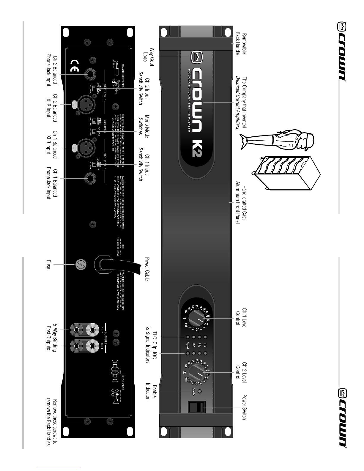
1.1 The
K-Series
Amplifier.................................... 10-11
1.2 The Big Picture: Controls, Indicators and
Connectors ................................................... 12-13
2.1 Mounting Dimensions.......................................... 14
2.2 Mono Mode Switches.......................................... 15
2.3 Input Sensitivity Switch........................................ 15
2.4 Typical Input Wiring............................................. 16
2.5 Stereo Output Wiring........................................... 17
2.6 Bridge Mono Output Wiring................................. 18
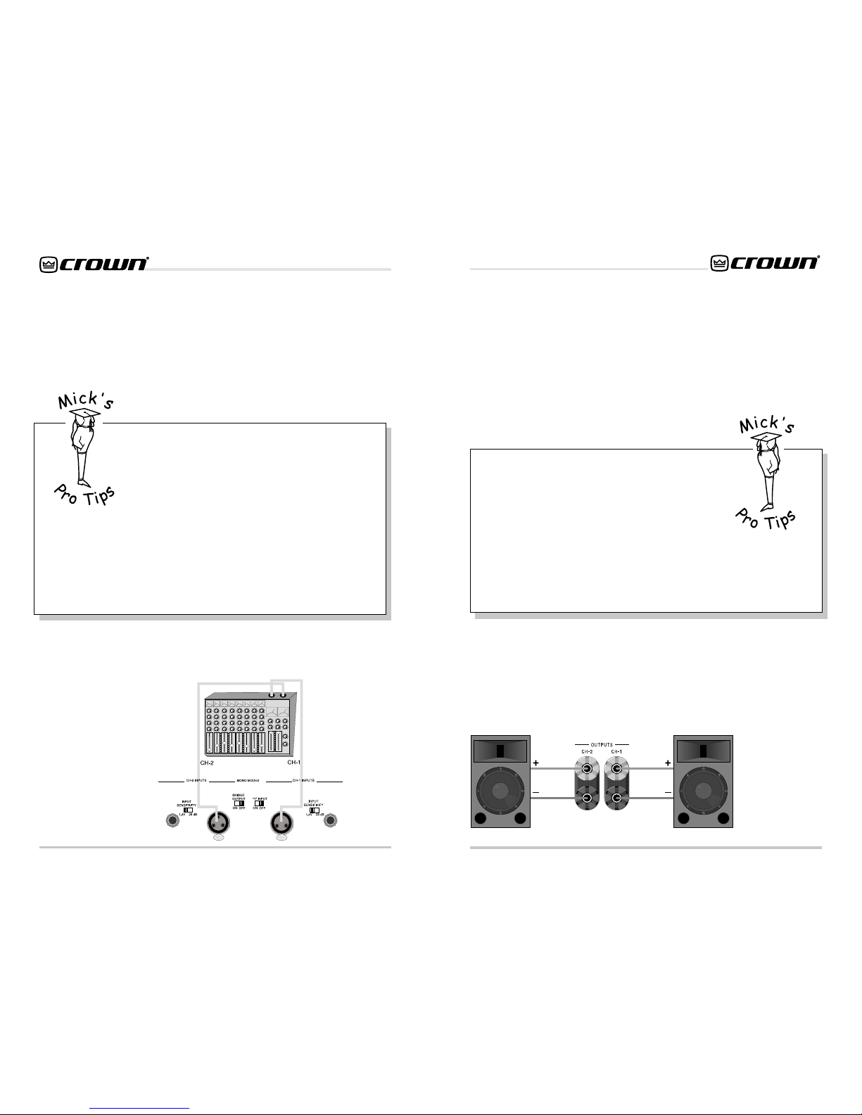
2.7 Stereo Hookup .................................................... 19
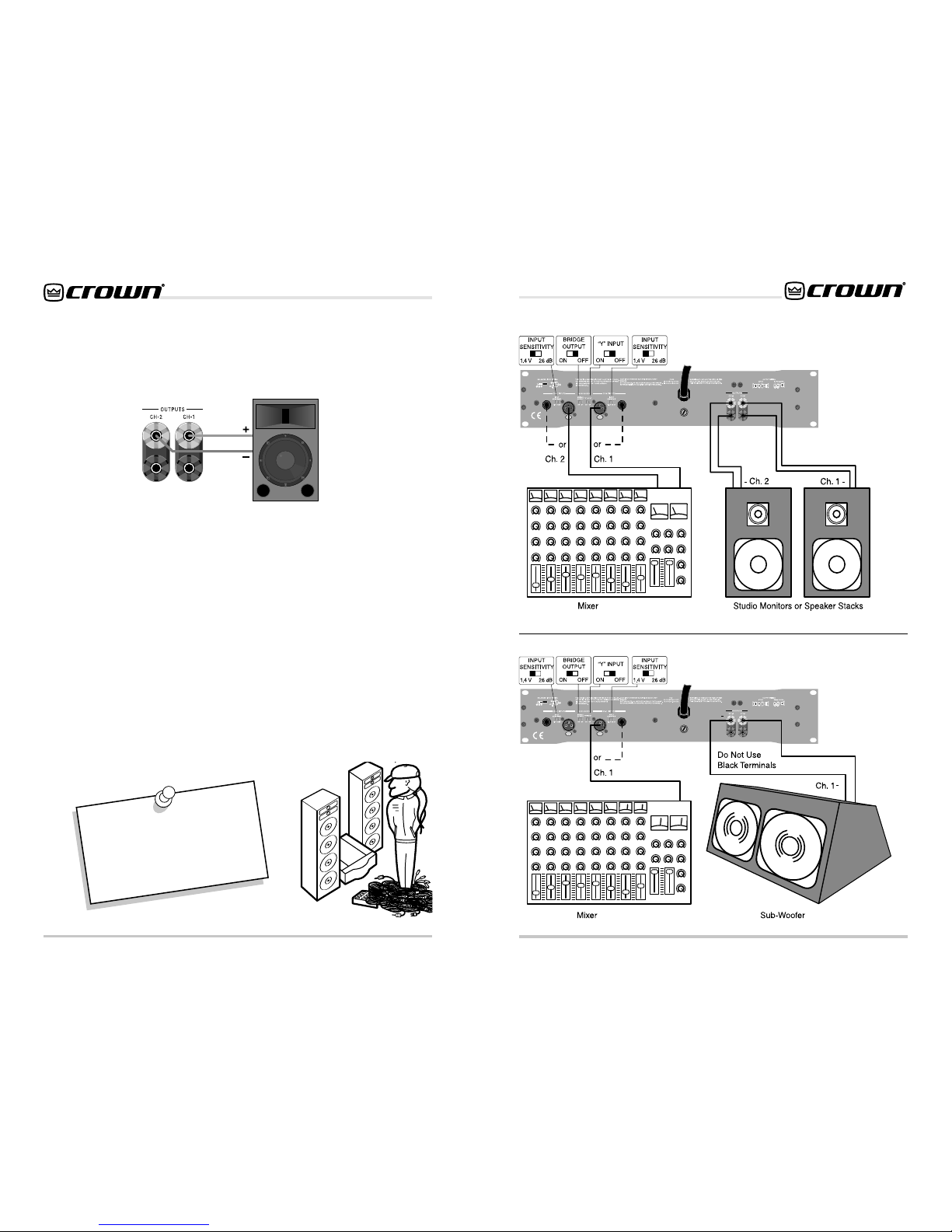
2.8 Bridged-Mono Output Hookup ............................ 19
2.9 “Y” Mono Input Hookup....................................... 20
2.10 “Y” Mono Input / Bridged Output ......................... 20
3.1 Front Panel Indicators & Controls ........................ 21
3.2 Back Panel Controls............................................ 23
3.3 Back Panel Fuse Location................................... 25
4.1 Balanced & Unbalanced Input Wiring ................. 28
4.2 Balanced Input Wiring......................................... 29
4.3 Unbalanced Input Wiring .................................... 30
5.1 Awesome Frequency (Amplitude) Response ...... 35
5.2 Superior Damping Factor .................................... 35
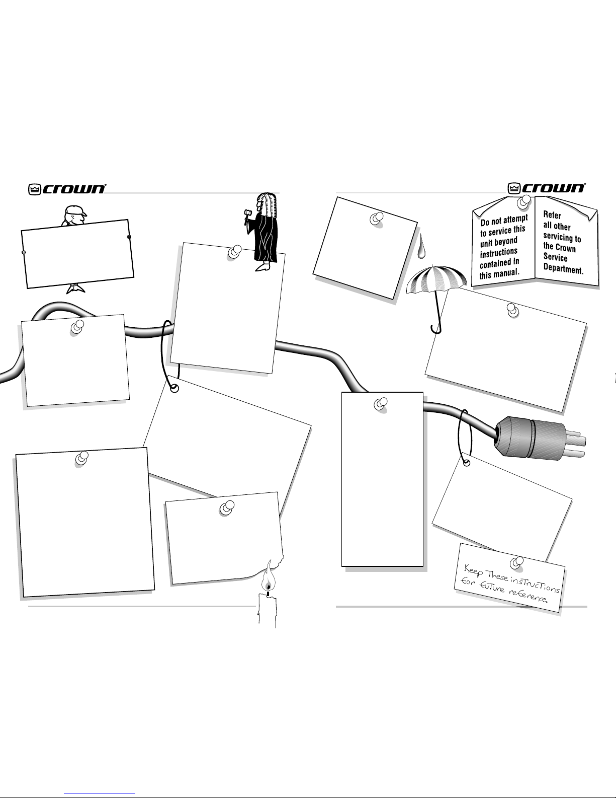
Important Safety Instructions
1) Read these instructions.
2) Keep these instructions.
3) Heed all warnings.
4) Follow all instructions.
5) Do not use this apparatus near water.
6) Clean only with a dry cloth.
7) Do not block any ventilation openings. Install in accor-
dance with the manufacturer’s instructions.
8) Do not install near any heat sources such as radiators,
heat registers, stoves, or other apparatus that produce
heat.
9) Do not defeat the safety purpose of the polarized or
grounding-type plug. A polarized plug has two blades
with one wider than the other. A grounding-type plug has
two blades and a third grounding prong. The wide blade
or the third prong is provided for your safety. If the pro-
vided plug does not fit into your outlet, consult an electri-
cian for replacement of the obsolete outlet.
10) Protect the power cord from being walked on or pinched,
particularly at plugs, convenience receptacles, and the
point where they exit from the apparatus.
11) Only use attachments/accessories specified by the
manufacturer.
12) Unplug this apparatus during lightning storms or when
unused for long periods of time.
13) Refer all servicing to qualified service personnel. Servic-
ing is required when the apparatus has been damaged in
any way, such as power-supply cord or plug is damaged,
liquid has been spilled or objects have fallen into the ap-
paratus, the apparatus has been exposed to rain or mois-
ture, does not operate normally, or has been dropped.