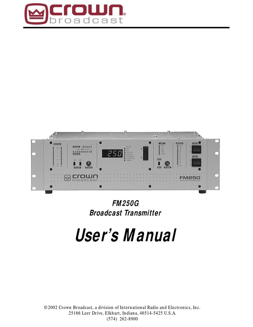
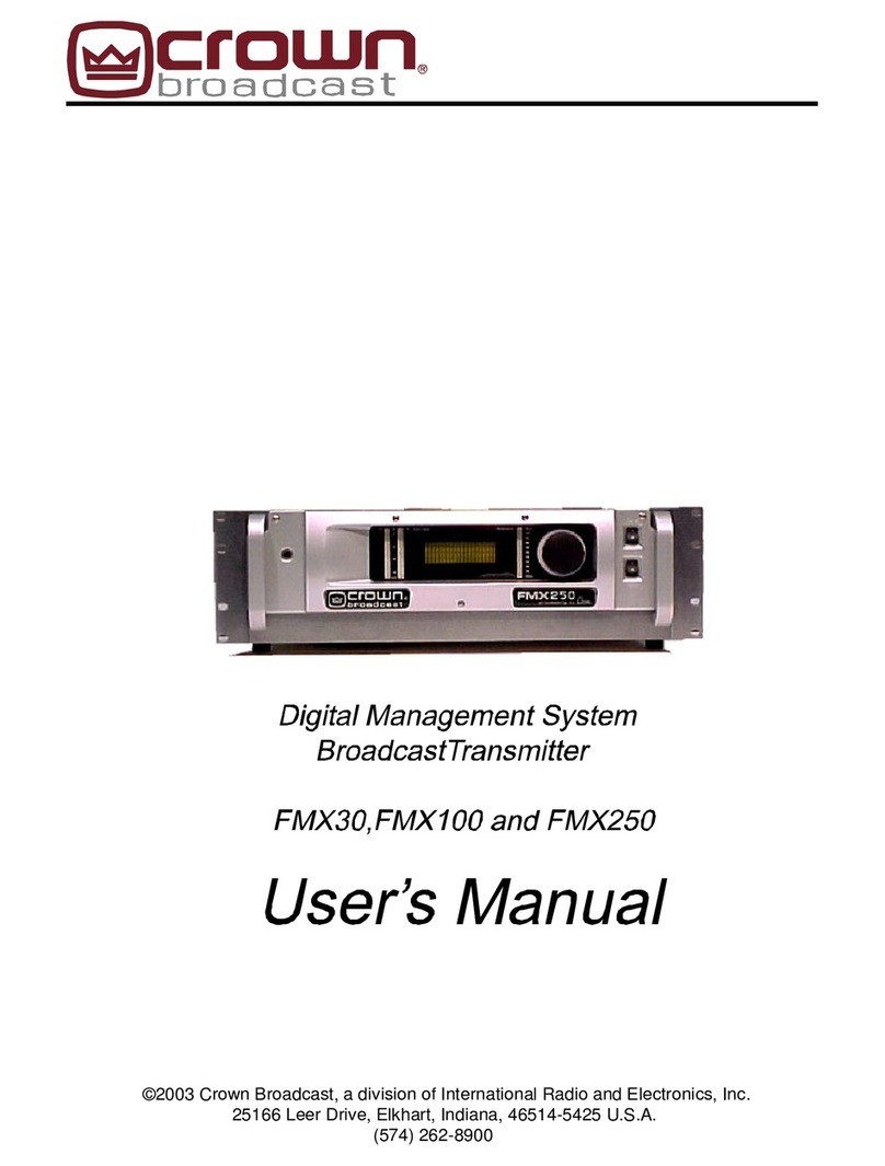
Crown FM5 User manual

FM5 Transmitter
User's Manual
©2020 Crown Broadcast, a division of
International Radio & Electronics Corporation
2524 Toledo Road, Elkhart, Indiana, 46516, U.S.A. (574) 262-8900

Revision Control
Revision Print Date
Initial Release 2020
Important Notices
©2020, Crown Broadcast, a division of International Radio & Electronics Corporation.
Portions of this document were originally copyrighted by Michael P. Axman in 1994.
All rights reserved. No part of this publication may be reproduced, transmitted, transcribed,
stored in a retrieval system, or translated into any language in any form by any means
without the written permission of International Radio & Electronics Corporation.
Printed in U.S.A.
Crown Broadcast attempts to provide information that is accurate, complete, and useful.
Should you find inadequacies in the text, please send your comments to the following
address:
International Radio & Electronics Corporation
2524 Toledo Rd,
Elkhart, IN 46516 U.S.A.
ii

Contents
Section 1– Getting Acquainted 1-1
1.1 Your Transmitter 1-2
1.2 Applications and Options 1-3
1.2.1 Stand Alone 1-4
1.2.2 FM5, SDoC approved 1-4
1.3 Transmitter/Exciter Specifications 1-5
1.5 Safety Considerations 1-7
1.5.1 Dangers 1-7
1.5.2 Warnings 1-7
1.5.3 Cautions 1-7
Section 2– Installation 2-1
2.1 Operating Environment 2-2
2.2 Power Connections - AC & Fuse 2-2
2.3 Frequency (Channel) Selection 2-3
2.3.1 Modulation Compensator 2-4
2.4 RF Connections 2-5
2.5 Audio Input Connections 2-6
2.6 Audio Output Connections 2-6
2.7 Composite Input Connection 2-7
2.8 Audio Monitor Connections 2-8
2.9 Pre-emphasis Selection 2-8
Section 3-Operation 3-1
3.1PowerSwitch 3-2
3.2 Peak Modulation 3-3
3.3 Stereo-Mono Switch 3-3
3.4 Frequency Selector Switch 3-3
3.5 RF Output Control 3-4
Service&Support 4-1
Glossary G-1
iii

FM5 User’s Manual

Section 1—Getting Acquainted
This section provides a general description of the FM5 transmitter and
introduces you to safety conventions used within this document. Review
this material before installing or operating the transmitter.
1-1Getting Acquainted

1.1 Your Transmitter
The FM5 is a member of a family of FM stereo broadcast transmitters. Crown
transmitters are known for their integration, ease-of-use, and reliability.
The integration is most apparent in the standard transmitter configuration which
incorporates stereo generation and RF amplification without compromised signal quality.
Ease-of-use is apparent in the user-friendly front panel interface and in the installation
procedure. Simply select your operating frequency (using 5 external switches), add an
audio source, attach an antenna, and connect AC power and you're ready to broadcast.
Reliability is a Crown tradition. The first Crown transmitters were designed for rigors of
worldwide and potentially portable use. The modular design, quality components,
engineering approach, and high production standards ensure stable performance.
Illustration 1-1 FM5 Stereo Broadcast Transmitter
1-2 FM5 User’s Manual

1.2 Applications and Options
Crown transmitters are designed for versatility in applications. The FM5 can be used as a
stand-alone transmitter and in nearcast applications. The following discussion describes
these applications further.
Model numbers describe the configuration of the product (which has to do with its intended
purpose) and the RF output power which you can expect.
The number portion of the name represents the maximum RF output power. The FM5 gen-
erates up to 5 watts of RF output power
The FM5 is the standard or transmitter configuration. In this configuration, the product
includes the following components (functions):
RF Exciter & Stereo Generator
RF Low-Pass filter
RF Amplifier
Power Supply
Illustration 1–2 Standard (Transmitter) Configuration
1-3Getting Acquainted
RF Exciter & Stereo Generator
RF Low Pass
Filtering
Power Supply
RF Amplifier

1.2.1 Stand-Alone
In the standard configuration, the FM5 is an ideal stand-alone transmitter. When you add an
audio source (monaural, L/R stereo, or composite signal), an antenna, and AC power, the
transmitter becomes a complete FM stereo broadcast station, capable of serving your small
venue requirements, whether inside a church, outside in a parking lot, football stadium, race
track or drive-in-theater.
1.2.2 FM5, SDoC approved
The FM5 is an SDoC (Supplier Declaration of Conformity) approved transmitter. (Go to
ecfr.gov and do a simple search Title 47, 2.906) This means Crown Broadcast must send
with the transmitter a Proof of Performance that states this transmitter meets or exceeds the
FCC requirements for an FM transmitter.
This transmitter can be used with an FCC granted STA (Special Temporary License. Go to
ecfr.gov and do a simple search Title 47, 5.61) An application must be sent to the FCC, if
approved it would give a Special Temporary License at a specific frequency, for a specific
area, for no more than 6 months.
You could also turn this transmitter down to 1 watt and transmit in compliance with Part 15
requirements as long as your antenna does not broadcast outside 250 μV/m at 3 m. You
need to be aware that the FCC requires Part 15 Transmitters to be approved by the FCC
and this transmitter does NOT have Part 15 approval and could be subject to heavy FCC
fines for operating without a license. See 3.5 for suggestions on how to reduce the chances
that you are violating Part 15.
To find vacant channels in your zip code area, go to radio-locator.com and choose the va-
cant channels option. It will request the zip code of the area you are wishing to broadcast in
and will give you any vacant channel options - best, good, and ok.
The following was copied from fcc.gov website:
PenalƟes for OperaƟon Without A Permit or License
The Commission considers unauthorized broadcast operaƟon to be a serious maƩer. Pres-
ently, the maximum penalty for operaƟng an unlicensed or "pirate" broadcast staƟon (one
which is not permiƩed under Part 15 or is not a Carrier Current StaƟon or Campus Radio
StaƟon) is set at $10,000 for a single violaƟon or a single day of operaƟon, up to a total
maximum amount of $75,000.
Adjustments may be made upwards or downwards depending on the circumstances in-
volved. Equipment used for an unauthorized operaƟon may also be confiscated. There are
also criminal penalƟes (fine and/or imprisonment) for "willfully and knowingly" operaƟng a
radio staƟon without a license. DON'T DO IT!
1-4 FM5 User’s Manual

1.3 Transmitter/Exciter Specifications
Frequency Range 87.9 MHz–107.9 MHz
RF Power Output (VSWR 1.7:1 or better)
FM5 0-5.5 Watts adjustable
RF Output Impedance 50Ohms
Frequency Stability Meets FCC specifications from 0-50
degrees C
Audio Input Impedance 50k Ωbridging, balanced, or 600 Ω
Audio Input Level Selectable for –10 dBm to +10 dBm for
75 kHz deviation at 400 Hz
Pre-emphasis Selectable for 50, 75 µsec or flat
Audio Response Conforms to 75 µsec pre-emphasis
curveasfollows:
Complete Transmitter ±0.30 dB (50 Hz–10 kHz)
±1.0 dB (10 kHz–15 kHz)
Exciter only ±0.25 dB (50 Hz–15 kHz)
Distortion (THD + Noise)
Complete Transmitter Less than 0.7% (at 15kHz)
Exciter only Less than 0.3% (50Hz-15kHz)
Stereo Separation
Complete Transmitter Better than –40dB (50Hz-15kHz)
Exciter only Better than –40dB (50Hz-15kHz)
Crosstalk Main into Sub, better than –40dB
Sub into Main, better than –40dB
Stereo Pilot 19 kHz ±2 Hz, 9% modulation
1-5Getting Acquainted

Subcarrier Suppression 50dB below ±75 kHz deviation
FM S/N Ratio (FM noise)
Complete Transmitter Better than –60dB
Exciter only Better than –70dB
AM S/N Ratio Asynchronous and synchronous noise
better than FCC requirements
RF Bandwidth ±120 kHz, better than –35 dB
±240 kHz, better than –45 dB
RF Spurious Products Better than –70dB
Operating Environment Temperature (0°C to 50°C)
Humidity (0 to 80% at 20°C)
Maximum Altitude (3,000 Meters;
9834 Feet
AC Power 120 volts +10%/-15%); 50/60Hz
1-6 FM5 User’s Manual
Note: We set voltage and ampere requirements to assist you in designing your system. De-
pending on your operating frequency, actual requirements for maximum voltage and current
readings are 10–15% lower than stated.
Regulatory
FM5 Type notified FCC SDoC
Meets FCC, DOC, and CCIR requirements
Dimensions 27.94 x 41.91 x 2.54 cm
11 x 16.5 x 1 inches
Weight
FM5 2.7 kg (6 lbs)
3.6 kg (8 lbs) shipping weight

1-7Getting Acquainted
1.4 Safety Considerations
Crown Broadcast assumes the responsibility for providing you with a safe product and
safety guidelines during its use. “Safety” means protection to all individuals who install,
operate, and service the transmitter as well as protection of the transmitter itself. To
promote safety, we use standard hazard alert labeling on the product and in this manual.
Follow the associated guidelines to avoid potential hazard.
1.4.1 Dangers
DANGER represents the most severe hazard alert. Extreme bodily harm or death will occur
if DANGER guidelines are not followed.
1.4.2 Warnings
WARNING represents hazards which could result in severe injury or death.
1.4.3 Cautions
CAUTION indicates potential personal injury, or equipment or property damage if the asso-
ciated guidelines are not followed. Particular cautions in this text also indicate unauthorized
radio-frequency operation.
Illustration 1–3 Sample Hazard Alert

FM5 User’s Manual

Section 2—Installation
This section provides important guidelines for installing your transmitter.
Review this information carefully for proper installation.
2-1Installation
2-3Installation 2-3Installation

2.1 Operating Environment
You can install the FM transmitter in a standard component rack or on a suitable surface
such as a bench or desk. In any case, the area should be as clean and well ventilated as
possible. Always allow for at least 2 cm of clearance under the unit for ventilation. If you set
the transmitter on a flat surface, install spacers on the bottom cover plate. If you install the
transmitter in a rack, provide adequate clearance above and below. Do not locate the trans-
mitter directly above a hot piece of equipment.
2.2 Power Connections - AC & Fuse
The FM5 operates on 120 volts AC (50 or 60 Hz; single phase).
The fuse holder is located on the back panel to the left of the On/Off switch.
Illustration 2–1 Fuse Holder
For 120 VAC operation, use the fuse installed at the factory.
Transmitter Input Power Fuse
FM5 100–120 V 6 A
Illustration 2–2 Fuse Reference Table
2-2 FM5 User’s Manual

2.3 Frequency (Channel) Selection
Your transmitter is capable of operating between 87.9 and 107.9 MHz in the FM band.
To adjust the operating frequency, follow these 0.1 MHz steps:
1. Locate the frequency selector switch on the front panel which will be used to change the
setting. See Illustrations 2–6 and 2–7.
2. Use small flat blade screwdriver or another suitable device to rotate the switches to the
desired setting. (The selected number will appear directly above the white indicator dot
on each switch.) See examples of selected frequencies in the illustration below.
Illustration 2–3 Front Panel
Megahertz .1
Illustration 2–4 Transmitter Front Panel (Frequency Selector Switches)
= 88.10 MHz
= 107.90 MHz
Illustration 2–5 Two Sample Frequency Selections
2-3
.01
3. To set the changed
frequency, either turn the
transmitter off and then
back on or press, the
black push button inside
the front panel opening
twice.
Illustration 2–6 Front Panel Opening
2-3
Installation

2.4 RF Connections & Antennas
Connect the RF load, an antenna or the input of an external power amplifier, to the type-N,
BNC output connector on the rear panel.
A simple antenna is included which will work for most applications.
However, if another antenna is attached, you will need to remove the top cover and clip or
unsolder the wire from the resistor to the BNC. See illustration 2-10 below.
Illustration 2–9 RF Output
2-4
RF Output
FM5 User’s Manual
Illustration 2–10
Cut or Unsolder before attaching a different antenna

2.5 Audio Input Connections
Attach audio inputs to the Left and Right XLR connectors on the rear panel. (The Left
channel audio is used on Mono.) Pin 1 of the XLR connector goes to chassis ground. Pins 2
and 3 represent a balanced differential input with an impedance of about 50 kΩ. They may
be connected to balanced or unbalanced left and right program sources.
The audio input cables should be shielded pairs, whether the source is balanced or unbal-
anced. For an unbalanced program source, one line (preferably the one connecting to pin 3)
should be grounded to the shield at the source. Audio will then connect to the line going to
pin 2.
Illustration 2–10 XLR Audio Input Connectors
By bringing the audio return line back to the program source, the balanced differential input
of the transmitter is used to best advantage to minimize noise. This practice is especially
helpful if the program lines are fairly long, but is a good practice for any distance.
2-5
Audio Inputs
(Female XLR)
2.6 Audio Output Connections
Attach audio outputs from the Left and Right XLR connectors on the rear panel. (The Left
channel audio is used on Mono.) Pin 1 of the XLR connector goes to chassis ground. Pins 2
and 3 represent a balanced differential input with an impedance of about 50 kΩ. They may
be connected to balanced or unbalanced left and right program sources.
The audio output cables should also be shielded pairs, whether the source is balanced or
unbalanced.
Audio Outputs
(Male XLR)
Illustration 2–11 XLR Audio Output Connectors
Installation

Illustration 2–13 Composite In Connection
2-6 FM5 User’s Manual
2.7 Composite Input Connection
You may feed composite stereo (or mono audio) directly to the RF exciter bypassing the
internal audio processor and stereo generator. To use the Crown transmitter with composite
input, it is necessary to use the Composite Input section of the transmitter. This will feed
composite stereo (or mono audio) directly to the RF exciter and will bypass the internal ste-
reo generator.
Input sensitivity is approximately 3.5–volt P-P for 75 kHz deviation.
1. Enable the Composite Input by adding a jumper across the pads of JP2
(see Illustration 2–12).
2. Connect the composite signal using the “Composite In” BNC connector.
RF Out
Illustration 2–12 Jumper JP2
Composite In

2.8 Audio Monitor Connections
Processed, de-emphasized samples of the left and right audio inputs to the stereo genera-
tor are available at the Monitor jacks on the rear panel. The signals are suitable for feeding
a studio monitor and for doing audio testing. De-emphasis is set for 75 µsec.
2.9 Pre-emphasis Selection
FM5 is set-up for 75 µsec. If you wish to change it to be 50 µsec or flat, please call the
Crown Service department and they will walk you through the steps.
2.10 Modulation Compensator
The Modulation trim-potentiometer is NOT a modulation control. This pot compensates for
slight variations in deviation sensitivity with frequency. From the factory, it is set for 50% or
midrange and this is where we recommend that it remain. However, if there is a reason that
this needs to be adjusted, go to Appendix A for details on how to do this.
Audio Monitor Jacks
Illustration 2–14 Audio Monitor Connections
2-7lnstallation

FM5 User’s Manual
Table of contents
Other Crown Transmitter manuals