NOSHOK 204 Series User manual

NOSHOK Inc. I 1010 West Bagley Road, Berea, OH 44017 I Ph: 440-243-0888 I Fax: 440-243-3472 I www.noshok.com
WARNING
Read this manual before working with the product. For personal and system safety and for optimum product
performance, make sure you thoroughly understand the contents before installing, using, or maintaining the
NOSHOK 204 & 304 Series Transmitters. Read the precautions and warnings on the last page.
204 Series
304 Series

Page 2
TABLE OF CONTENTS
SECTION PAGE
1 Introduction 3
2 Installing Transmitter 3
2.1 Mounting position 3
2.2 Mounting position effect 3
2.3 Calibration 3
2.4 Wiring 4
3 Remaining 4
3.1 Digital Local indicator 4
3.2 CE / EMC - Rules 4
3.3 External load 4
4 Push Buttons Functions 5
4.1 Programming points (P101-P114) 6
4.2 Reading on display 6
4.3 Explanation of programming points 7
P101 Zero adjustment (4 mA) 7
P102 Span adjustment (20 mA) 7
P103 Cancel mounting position effect 7
P104 Pressure unit on display 8
P105 Output: 4-20 mA or 20-4 mA 8
P106 Damping adjustment 9
P107 Process Temperature indication 9
P108 Temperature °F or °C 9
P109 Readout on Display 9
P110 Simulation of current (4-20 mA) 9
P111 Linearization 10-12
P112 Specific density 12
P113 Write protection 12
P114 Response time from push buttons 13
P115 Service-menu 19
P116 Service-menu 19

Page 3
1 INTRODUCTION
NOSHOK 204 & 304 Series Intelligent Sanitary Transmitters are solid-state pressure and level
transmitters using a piezoresistive silicone sensor with a very high burst pressure. The sensor
element is mounted in a Stainless Steel foot. Inside the foot a temperature sensor is also mounted to
provide active temperature compensation at the point of measurement, to minimize temperature and position
error. A compact, robust Stainless Steel flush diaphragm minimizes the amount of fill fluid and reduces the
potential for damage. Diaphragms are laser welded and helium leak tested. A very small amount of oil fills
the chamber surrounding the sensor and transfers pressure from the flush mounted diaphragm to the sensor.
Pressure on the sensor element creates a very small deflection of the silicon substrate and bridge
network. The resulting strain in the silicon resistors causes a change in the bridge resistance proportional
to the pressure applied. The transmitter electronics detects this change in bridge resistance and converts
it into 4-20 mA. The amplifier system is based on a single Integrated Circuit, which ensures a perfect
linearity in the 4-20 mA output. The flush diaphragm technology ensures reliable long-term stability.
The All Stainless Steel pressure transmitters are based on a ceramic pressure cell, with very high burst
pressure. These transmitters do not have oil filling.
2 INSTALLING THE TRANSMITTER
The diaphragm of the transmitter is protected with a special protection cap. Protect the diaphragm until
installation takes place. DO NOT DAMAGE THE DIAPHRAGM
1. Make sure to correctly locate the packing within the tank shell
2. Improper installation of the packing can cause a process leak.
3. Position the transmitter into the tank shell and begin engaging threads.
4. The transmitter can be rotated prior to seating enabling the user to optimize access to
calibration adjustments, cable entry, and local indicator.
5. Once the Lock ring (9) has been hand tightened, it must be tightened with an additional turn
with adjustable pliers (± 1/8").
2.1 MOUNTING POSITION
When the transmitter is mounted horizontally, the cable gland must be pointed downwards.
2.2 MOUNTING POSITION EFFECT
All transmitters are calibrated in vertical position. If the transmitter is mounted in another position, there
can be a little zero shift. (4.02 mA instead of 4.00 mA). If the transmitter is mounted down, there is a zero
shift (For example 3.98 mA instead of 4.00 mA). After installation of the transmitter the zero must be set
to 4.00 mA with P103 in the programming mode. This will not affect the span.
2.3 CALIBRATION
All transmitters are fully calibrated at the factory to full span, unless otherwise specified by the
customer.
Page 4
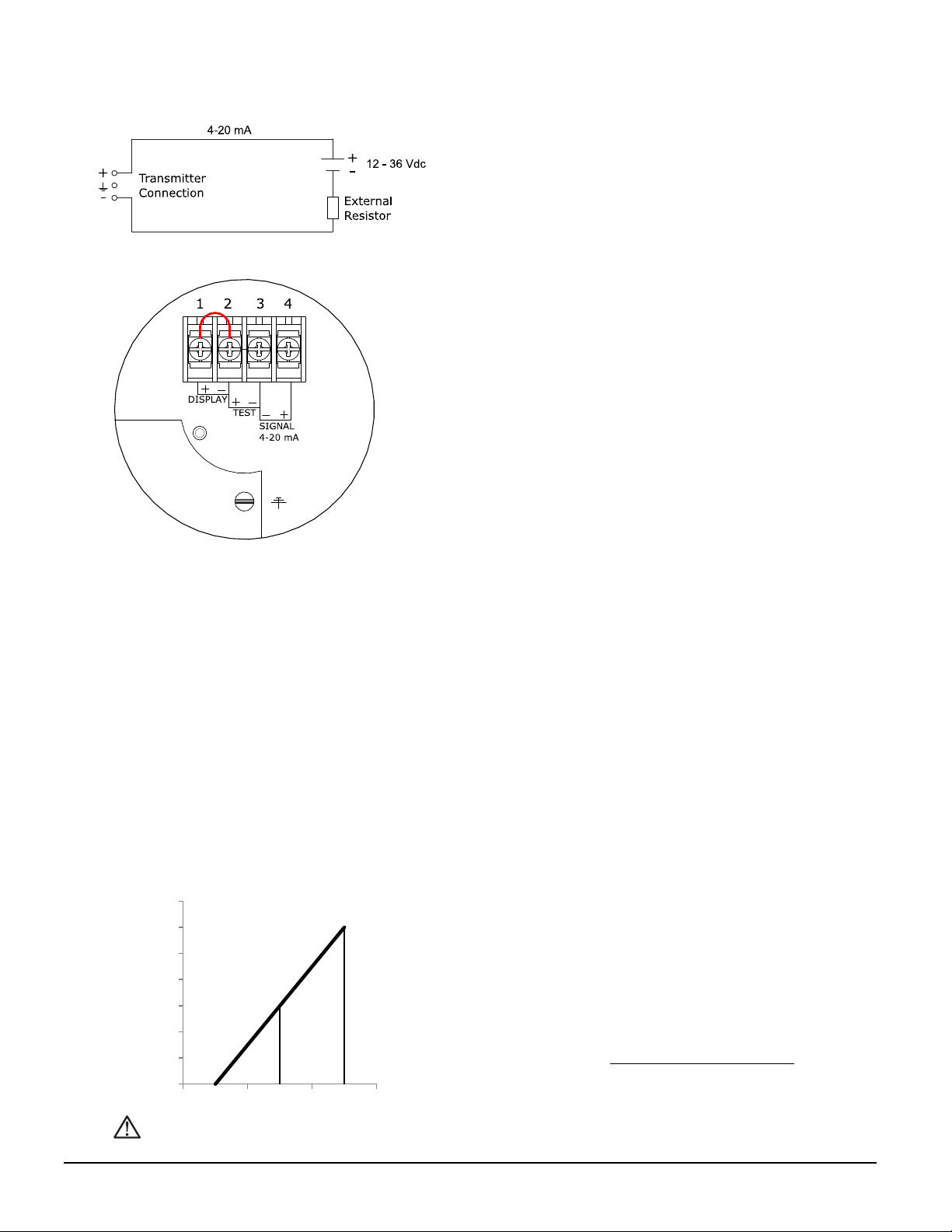
2.4 WIRING
Under the cover (3) you will find the terminal board.
The push buttons "Zero", "Span" and "Prog" are
under the other cover (1). External loads must be
placed in the negative side of the 2-wire loop.
The figure left shows the wiring connection of the
transmitter. The 2-wires must be connected to 3 (-)
and 4 (+) of the terminal board.
The transmitter must always be connected to
earth. The transmitter must be connected with
standard two-wire shielded cable. Do not run signal
wiring in open trays with power wiring, or near heavy
electrical equipment (Frequency controller or heavy
pumps). Shielding must always be connected at the
side of the power supply. In case the process
connection is already connected to ground (e.g. via
the tank or pipe line) Do not connect the instrument
to ground. Please ensure that the instrument is
not connected to ground twice to prevent an
'earth loop'. In applications with synthetic process
connections, the enclosure (internal or external)
must be connected to ground.
3. REMAINING
3.1 DIGITAL LOCAL INDICATOR
NOSHOK 204 & 304 Series transmitters are standard equipped with a digital display. As standard
transmitters are delivered with closed covers. The three push buttons and the display are behind the
cover (1). As an option a Transparent cover can be delivered to achieve the display can be used as a
local display in the process. The display can be set to any value between 0000 and 9999 (4 digit). (Option:
"I" extra price).
3.2 CE / EMC - RULES
These are manufactured in accordance with the RFI/EMC directives and comply with the CE standard.
These transmitters are fitted with RFI filters, which provide optimum, trouble-free operation, and are in
conformity with EMC-Directive 2014/30/EU based on test results using harmonized standards.
3.3 EXTERNAL LOAD
The minimum power supply is based on the total circuit
resistance. The maximum permissible load (Ri max.) in
case of 24 Vdc is 600 Ω (Ohm).
By increasing the power supply, the external load can be
increased to 1200 Ohm / 36 Vdc.
(see figure left).
RI max = Power Supply - 12 Vdc
20 mA
With a loop resistance of 250 Ω a power supply of at least 17 Vdc must be used.
0
200
400
600
800
1000
1200
1400
12 24 36
Page 5
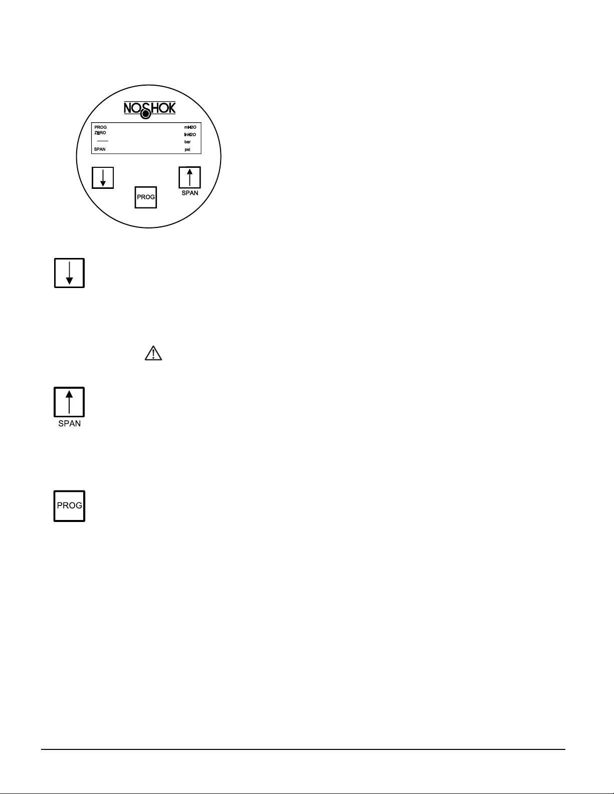
4 PUSH BUTTONS FUNCTIONS
The NOSHOK 204 & 304 Series Transmitters can be programmed
easily by use of the 3 front panel pushbuttons. The display can show
engineering units of inH2O, mH2O, bar and PSI.
The functions of the three pushbuttons will be explained below.
This button has 2 functions:
•It can be directly used for adjusting the zero (4 mA), with or without a test pressure. When
the zero (4 mA) must be adjusted at 0 (atmospheric pressure), the button must be held
until the word "Zero" appears on the display. The transmitter is now set to 4 mA.
•This button must be used for stepping down in the menu or to decrease a value (-).
For canceling the mounting position effect you have to use P103.
This button has 2 functions:
•It can be directly used for adjusting the span (20 mA), when using a test pressure (air).
When a test pressure (e.g. 2 bar) is supplied to the transmitter, the button must be held
until the word "SPAN" appears on the display. The transmitter is adjusted at 20 mA now.
The span can also be adjusted without test pressure (see P102).
•This button must be used for stepping up in the menu or to increase a value (+).
This button has 2 functions:
•It is used to adjust the Programming Points (P101 till P114). Push it once and P100 is
displayed, use the [↑] (SPAN) to step to P101.
•This button must also be used for confirming the adjustments (enter).
For example, if you want to change the adjustment in psi (P104),
the following steps must be taken:
1. Push on [PROG] till "100" appears on the display.
2. Push on [SPAN] 4 times to go to point "P104" (adjustment pressure unit).
3. Push [PROG] to confirm this.
4. Push several times on [↑] (SPAN) to reach 3 (= bar). (Conversion table page 11).
5. 1 = mWC, 3 = bar, 5 = PSI, 11 = inch WC
6. Confirm this by pushing once at [PROG].
7. The transmitter is now adjusted to read in psi.

Page 6
4.1 PROGRAMMING POINTS (P101 – P114)
The following points can be adjusted with the three
push buttons. For an explanation of these points see
the following pages of this manual.
To change one of these points you have to push on
[PROG] until "100" appears on the display.
To go from a lower program (P101) to a higher one
(P102), push on button [↑] (SPAN). To confirm the
adjustments, you always have to press on [PROG].
*) Standard adjustments ex works.
4.2 READING ON THE DISPLAY
On the standard built-in display several values can be
shown. When the transmitter is in the process the
display gives all the information of the process
pressure or temperature. On the display the following
units are available: mH2O, inH2O, bar and PSI (see
P104 and P109).
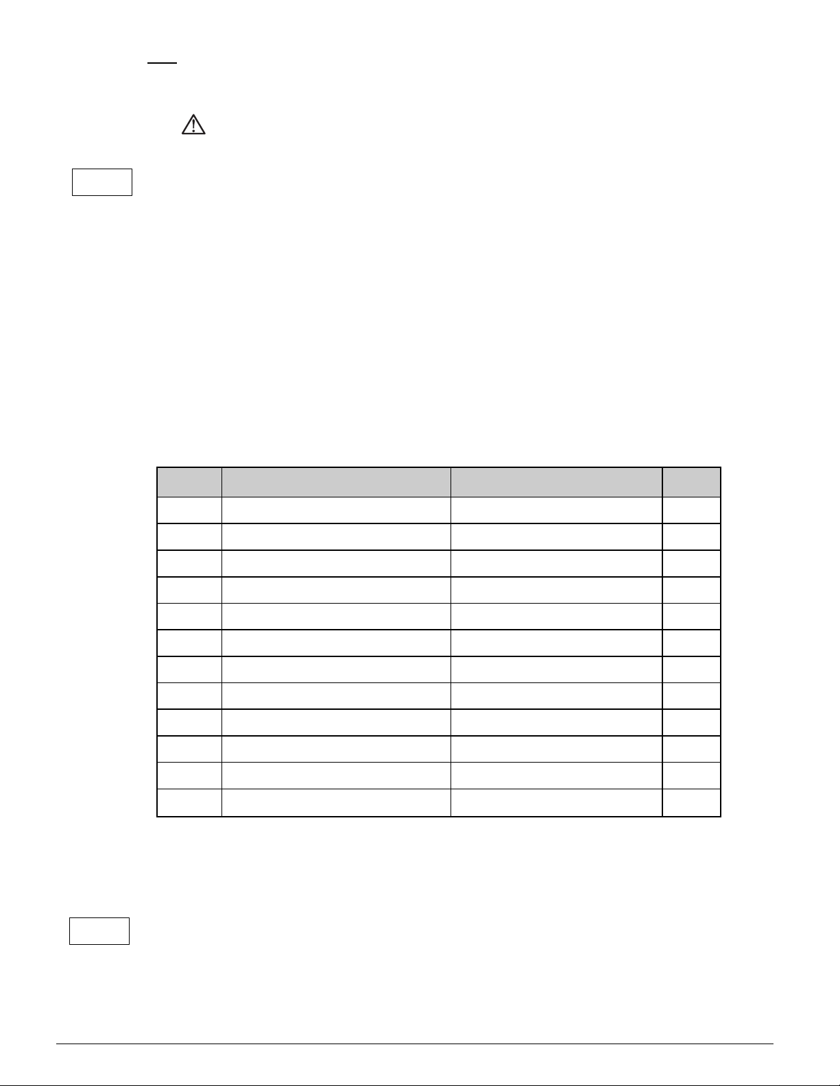
Programming points
P101 Zero adjustment (4 mA)
P102 Span adjustment (20 mA)
P103 Cancel mounting position effect
P104
Adjustment pressure unit
(See Conversion table)
P105
4-20 mA *)
20-4 mA (Reverse output)
P106 Adjustment damping (0 to 25 sec)
P107
Indication of process temp. (Read out on
display)
P108
0 = °C (*)
1 = °F
P109
Read out on display:
Curr (0) = Current (4 - 20 mA) (*)
Unit (1) = Pressure unit (conversion table)
PerC (2) = Percentage
TenP (3) = Temperature
Hect (4) = Hectoliters
CBn (5) = Cubic meters
Ltr (6) = Liters
P110 Simulation of current
P111
Linearization
0 = No Linearization (*)
1 = Cylindrical tank
2 = Vertical tank with cone
3 = Vertical tank with spherical cone
P112 Specific density
P113 Write Protection
P114 Response time from push buttons

Page 7
4.3 EXPLANATION PROGRAMMING POINTS P101 to P114
ZERO ADJUSTMENT (4 mA)
The transmitter as standard is adjusted to 4.00 mA at atmospheric pressure.
It is also possible to adjust a zero-suppression or elevation.
For example: Zero elevation of 1.45 psi.
1. Push at [PROG] until "100" is shown on the display.
2. Push once at [↑] / SPAN till "101".
3. Confirm this by pushing [PROG].
4. Now the display will show 0.00 mH2O. Push at [↑] till 1.45 psi is on the display.
5. Confirm with [PROG].
6. The output of the transmitter will be lower than 4 mA. The output at atmospheric
pressure will be for example 3.68 mA. When a pressure of 1.45 psi is applied on the
diaphragm the output will be 4.00 mA.
The elevation can be canceled by pushing at [↓] till zero disappears out of the display. The transmitter is
now adjusted at 4 mA at atmospheric pressure.
SPAN ADJUSTMENT (20 mA) WITHOUT TEST PRESSURE
Before adjusting the span make sure the right pressure unit is selected.
(See also P104 and P109).
Example: Adjustment of the span at 0 - 29 psi.
First off all, the pressure unit must be adjusted at psi. (See P104).
1. Push [PROG] till "100" is shown on the display.
2. Push twice at [↑] / SPAN until "102" appears on the display.
3. Confirm this by pushing [PROG].
4. Push [SPAN] (+) or [ZERO] (-) to select the measuring range that is required.
5. Confirm by pushing [PROG].
The transmitter is adjusted now.
P102 is the adjustment of the total span.
When a compound range must be adjusted (for example -14.5 till +43.5 psi), a span of 29 psi must be
programmed.
The Zero (P101) must be set at -14.5 psi. The transmitter is adjusted at - 14.5 psi = Zero and +43.5 psi =
Span.
CANCEL MOUNTING POSITION EFFECT
All transmitters are calibrated vertically. When NOSHOK 204 & 304 Series Transmitters are
installed horizontally, there will be a small "mounting effect" on the zero (4 mA). For example, the
transmitter shows 4.03 mA instead of 4.00 mA. This can be easily canceled with P103. In P103
there are three options:
ESC
Nothing will be changed. Leave without doing anything. (confirm with PROG).
RESET
Use this option when you are not sure if P103/SET has been done in a proper way. (confirm
with PROG). When using this option, the original factory setting will be valid.
P101
P102
I
P103
Page 8
SET
Canceling mounting position effect. (confirm with PROG). When SET is selected the transmitter
is automatically adjusted at 4.00 mA. The span will not be affected.
Do not apply pressure while executing "cancel mounting position effect"
ADJUSTMENT PRESSURE UNIT ON DISPLAY (See Conversion table)
Several engineering units can be shown on the display by using a conversion factor.
(See conversion table below). As standard the pressure unit of the transmitter is set to bar. Four
engineering units can be used for displaying the applied pressure on the display (mH2O,
inH2O, bar and PSI).
This will be explained with an example (psi):
1. Push at [PROG] till "100" is shown on the display.
2. Push 4 times at [↑], go to [P104].
3. Push at [PROG] to confirm this.
4. Push at [↑] and adjust at 5 (= psi).
1 = mH2O (= mWC), 3 = bar, 5 = psi, 11 = inchH2O (= inchWC).
5. Confirm with [PROG].
The transmitter will now read out in psi.
CONVERSION TABLE:
104 CONVERSION FACTOR DISPLAY
1 1.000 mH2O (mWC)
*
2 1000 mmH2O (mm WC)
3 0.09806 bar
*
4 98.0665 mbar
5 1.4223 psi
*
6 0.0967 Atm
7 9.80665 KPa
8 0.009807 MPa
9 0.1 Kgf/cm2
10 73.556 mm HG
11 39.37 inH20 ("WC)
*
12 2.895906 "HG
To show one of the engineering units, P109 must be adjusted at 1 (= Pressure unit).
*) Pressure units that can be shown on the display. When the value of the highest range is larger
than 9999, "NA" will appear in the display (Not Applicable). Another unit must be chosen.
REVERSE OUTPUT (20 - 4 mA)
The transmitter as standard is adjusted to 4-20 mA output.
Push on [PROG] and go to P105.
Push once at [↑] to change the output to 20-4 mA (Reverse output).
Push at [PROG] to confirm this.
Now the transmitter will give 20 mA at atmospheric pressure.
P104
P105

Page 9
ADJUSTMENT DAMPING (0 till 25 sec)
In P106 an electronic damping can be adjusted between 0 and 25 seconds.
This can be done with the push buttons [↑] (up) and [↓] (down).
Always confirm by pushing once at [PROG].
INDICATION OF PROCESS TEMPERATURE (READ OUT ON DISPLAY)
1. Push [PROG] until "100" is shown on the display.
2. Push 7 times at [↑], go to [P107].
3. Push [PROG] to confirm this. Now the process temperature appears on the
display (Indication: +/-2°C).
This will remain on the display. To get the actual pressure back on the display you have to push
again on P107 until the actual pressure appears on the display again.
TEMPERATURE IN °F OR °C
The temperature of the transmitter is standard adjusted at °F (FAHR). When pushing at [↑] in
P108, this will change into °C (CELC). Always confirm by pushing once at [PROG].
READ OUT ON DISPLAY
Curr (0) = current (4 - 20 mA)
Unit (1) = pressure unit (See conversion table)
PErC (2) = percentages (0 - 100%)
TEnP (3) = temperature (°F of °C) Indication of process temperature, accuracy depending on sensor position.
HECt (4) = hectoliter (only in combination with P111)
Cb n (5) = Cubic meter (only in combination with P111)
Ltr (6) = Liters (only in combination with P111)
FREE (7) = Free adjustable scale (only in combination with P111)
As standard the transmitter read out is in mA (0).To change this, follow the next steps:
1. Push [PROG] until "100" is shown on the display.
2. Push 9 times at [↑] / SPAN till "109" appears on the display.
3. Confirm with [PROG].
4. Push once at [↑].
5. Push [PROG] to confirm this.
The transmitter will now read mH2O (mWC).
The pressure unit can be changed with the conversion table in P104.
1 = mH2O (=mWC), 3 = bar, 5 = psi, 11 = inchH2O (inchWC).
The read out can also be in 0 - 100%. Select P109, option 2.
SIMULATION OF CURRENT (4-20 mA)
The transmitter can be used as a simulator of a current between 4 - 20 mA.
This can be done in P110 with the push buttons [↑] and [↓].
The user can perform a current simulation (Curr) or a pressure simulation (Unit).
Current-simulation (Curr)
To perform a current-simulation follow the next steps:
1. Push [PROG] until "100" is shown on the display.
2. Push 10 times at [↑] / SPAN till "110" appears on the display.
3. Confirm with [PROG].
P106
P107
P108
P109
P110

Page 10
4. The display will readout 'Curr'
5. Confirm with [PROG].
6. The display shows '4.00'. Push [PROG] and the output changes to 4.00 mA.
7. By pushing [↑] / SPAN or [↓] / ZERO, you can change the value on the display. The
output value will change as soon as the [↑] / SPAN OR [↓] / ZERO button is released.
8. Pressing the [PROG]-button again will exit the simulation.
Pressure-simulation (Unit)
To perform a pressure-simulation follow the next steps:
1. Push [PROG] until "100" is shown on the display.
2. Push 10 times at [↑] / SPAN till "110" appears on the display.
3. Confirm with [PROG].
4. The display will readout 'Curr'
5. Press [↑] / SPAN once
6. The display will readout 'Unit'.
7. Confirm with [PROG].
8. The display shows a pressure value. Push [PROG] and the output changes to a mA-
output corresponding with the range entered in menu P101 and P102.
9. By pushing [↑] / SPAN or [↓] / ZERO, you can change the value on the display. The
output value will change as soon as the [↑] / SPAN OR [↓] / ZERO button is released.
10. Pressing the [PROG] button again will exit the simulation.
The values that can be entered using the pressure-simulation are related to the adjustments in
menu P101 and P102. These values are also the minimum and maximum values.
HART: This menu will not work when the device is operating in multi-drop mode.
LINEARIZATION
0 = no Linearization
1 = cylindrical tank (horizontal)
2 = tank with bottom cone
3 = tank with spherical bottom
4 = Free adjustable scale (Linear) (Option G79)
As standard the transmitter is delivered without Linearization (= 0). However, for a horizontal
tank or a tank with a bottom cone, a Linearization can be applied to achieve the current signal
(mA) is equal to the level in the tank. All values must be programmed in meters.
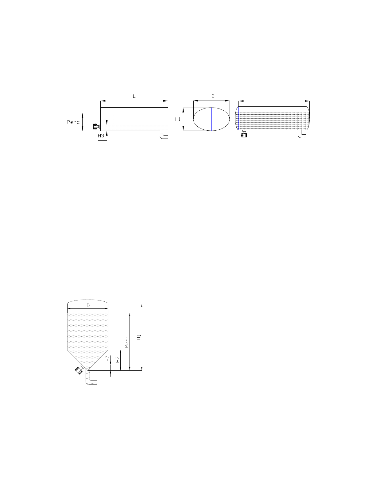
Linearization horizontal tank (Cylindrical)
1. Push [PROG] until "100" is shown on the display.
2. Push 11 x at [↑] / SPAN till "111" appears. (Confirm with [PROG])
3. Push [↑] once. (Confirm with [PROG])
4. Enter the height (H1) of the tank in meters. (Confirm with [PROG])
5. Enter the same height (H2) of the tank in meters. (Confirm with [PROG])
P111
Cylindrical horizontal tank Cylindrical tank with cone-shaped ends
Page 11
6. Enter the length (L) of the tank. For a "ball" or cone shaped tank, take the cylindrical
length plus the length of 1 "ball" cone. (Confirm with [PROG])
7. Enter H3 in meters if the transmitter is installed like in the left picture. Enter 0m when the
transmitter is installed like in the right picture.
8. Enter the percentage of the actual "full" level (for example 80%).
(Confirm with [PROG]).
Linearization horizontal tank (Elliptic)
1. Push [PROG] until "100" is shown on the display.
2. Push 11 x at [↑] / SPAN till "111" appears. (Confirm with [PROG])
3. Push [↑] once. (Confirm with [PROG])
4. Enter the height (H1) of the tank in meters. (Confirm with [PROG])
5. Enter the height (H2) of the tank in meters. (Confirm with [PROG])
6. Enter the length (L) of the tank. For a "ball" or cone shaped tank, take the cylindrical
length plus the length of 1 "ball" cone. (Confirm with [PROG])
7. Enter H3 in meters if the transmitter is installed like in the left picture. Enter 0m when the
transmitter is installed like the right picture.
8. Enter the percentage of the actual "full" level (for example 80%).
(Confirm with [PROG]).
If the height (H) of the tank is 1 meter and the maximum level in the tank is 0,8 meter the percentage (point 8) must
be set at 80%. The calibration at P102 must be adjusted at: 1 meter (if specific gravity equals 1).
Linearization vertical tank with cone
1. Push [PROG] till "100" appears on the display.
2. Push 11 times at [↑] till "111" appears.
3. (Confirm with [PROG])
4. Push twice at [↑]. (Confirm with [PROG])
5. Enter height (H1) of the tank (= actual level).
(Confirm with [PROG]).
6. Enter diameter (D) of tank. (Confirm with [PROG])
7. Enter height (H2) of cone. (Confirm with [PROG])
8. Enter the height (H3) from the bottom of the tank to
the topside of the diaphragm (or weld-on nipple).
(Confirm with [PROG]).
9. Enter the percentage of the actual "full" level (for
example 80%).(Confirm with [PROG]).
Cylindrical horizontal tank Cylindrical tank with cone-shaped ends

Page 12
Linearization vertical tank with spherical cone
1. Push [PROG] till "100" appears on the display.
2. Push 11 times at [↑] till "111" appears.
3. (Confirm with [PROG])
4. Push three times at [↑]. (Confirm with [PROG])
5. Enter height (H1) of the tank (= actual level).
(Confirm with [PROG]).
6. Enter diameter (D) of tank. (Confirm with [PROG])
7. Enter height (H2) of cone. (Confirm with [PROG])
8. Enter the height (H3) from the bottom of the tank
to the topside of the diaphragm (or weld-on nipple)
(Confirm with [PROG]).
9. Enter the percentage of the actual "full" level (for
example 80%).(Confirm with [PROG]).
When the specific gravity of the fluid is unequal to 1 and you do not want to use option 4, you must take care of
defining of the calibration of the transmitter. Calibration (see P102) = Height of the level x Specific Gravity.
FREE ADJUSTABLE SCALE (Option G79)
1. Push [PROG] till "100" appears on the display.
2. Push 11 times at [↑] till "111" appears. Confirm with [PROG].
3. Navigate to FREE with the arrow [↑] buttons. (Confirm with [PROG])
4. The next step is entering the amount of digits of the reading. With the arrow [↑] buttons
the decimal can be changed to left or right.
5. SET MIN appears on the display, and the minimum value can be set, by using the
arrow [↑] buttons. Confirm with [PROG]).
6. SET MAX appears on the display, and the maximum value can be set, by using the
arrow [↑] buttons. Confirm with [PROG].
7. To display this configuration on the display, navigate to P109.
Choose FREE and confirm with [PROG].
SPECIFIC DENSITY
If the specific gravity of the medium differs from 1 kg/dm3, you can enter the real density of the
medium in P112. When this option is used, the actual height of the tank must be entered.
WRITE PROTECTION
The NOSHOK 204 & 304 Series Transmitters with HART-Protocol can be protected for
adjustment (Write Protection). This is possible for two kinds of adjustments:
Local changes with pushbuttons and display (Lo.Pr = Local Protection).
Changes by external HART configuration software (Handheld terminal or PC).
(Co.Pr. = Communication Protection).
As standard, the transmitter is set to no-write protection.
Adjustment Local Protection
1. Push [PROG] till "100" appears on the display.
2. Push [↑] / SPAN 13 times till "113" appears on the display.
3. Push [PROG] to confirm. ("Lo.Pr." appears on the display).
4. Push [↑]/[↓] for adjusting to "ON" or "OFF".
5. Push [PROG] to confirm.
P112
P113

Page 13
Adjustment Communication Protection
1. Push [PROG] till "100" appears on the display.
2. Push [↑] / SPAN 13 times till "113" appears on the display.
3. Push [PROG] to confirm. ("Lo.Pr." appears on the display).
4. Push once more at [PROG]. ("Co.Pr." appears on the display).
5. Push [↑]/[↓] for adjusting to "ON" or "OFF".
6. Push [PROG] to confirm.
When Lo.Pr. is set to "ON", the display shows PROT for program point: 104, 105, 107, 108, 109 and 111. Both
protections can be adjusted at the same time, independent from each other.
RESPONSE TIME FROM PUSH BUTTONS
The response time from the push buttons can be adjusted from 0.0 till 5.0 seconds.
P115 & P116: SERVICE MENU
Only available for manufacturer.
P114
CORPORATE HEADQUARTERS
1010 West Bagley Road, Berea, Ohio 44017
Ph: 440-243-0888 Fax 440-243-3472
E-mail: [email protected]
Web: www.noshok.com
NK19204TUM
This manual suits for next models
1
Table of contents
Other NOSHOK Transmitter manuals

NOSHOK
NOSHOK 623 Series User manual

NOSHOK
NOSHOK PT40 Series User manual

NOSHOK
NOSHOK 800 Series User manual

NOSHOK
NOSHOK KING-GAGE ES2 5501 User manual

NOSHOK
NOSHOK 850 Series User manual

NOSHOK
NOSHOK 810 series User manual

NOSHOK
NOSHOK 621 Series User manual

NOSHOK
NOSHOK PT41 Series User manual

NOSHOK
NOSHOK KING-GAGE 5900 Use and care manual

NOSHOK
NOSHOK King-Gage 5800 Series Service manual


