CRU Ditto Foensic FieldStation User manual


PMS711 2cyan
85magenta
76yellow
10.25.12
CRU Mark
Page 2
1.2 Identing Parts
Take a moment to familiarize yourself with the parts of the
Ditto. This will help you to better understand the following
instructions.
1. Pre-Installation Steps 2
1.1 Box Contents 2
1.2 Identifying Parts 2
2. Setup 3
3. Web Browser Interface 3
3.1 Accessing the Web Browser Interface 3
4 Home Screen 4
4.1 Action 4
4.2 Investigation Info Panel 5
4.3 Settings 5
4.4 Current Status 5
4.5 Disks 5
4.6 System Log 5
4.7 Advanced Features/functions 5
4.7.1 Usage of NetView Scan 5
4.7.2 Target Mode 8
4.7.3 Using Network Source and Destination 9
5. Congure Screen 11
6. Admin 13
7. Logs 13
8. Utilities 14
9. Usage of Ditto Through the LCD 14
9.1 Status Screen 14
9.2 Settings 15
9.3 Disk Info 15
9.4 Perform Action 15
9.6 Factory Reset 16
10. Technical Specications 17
Top of Unit
Power Available LEDs
LCD Menu
Destination LEDs
Navigation buttons for LCD Menu
Source LEDs
Source Inputs
(all inputs are write-blocked)
RJ45 Gigabit Ethernet connection 4-pin Molex (DC Power Output)
PATA connection
Expansion Module connection
USB2 type A connection eSATA connection
Destination Outputs
RJ45 Gigabit Ethernet connectioneSATA connections
Stealth Mode Switch 4-pin Molex (DC Power Output)
Table of Contents
1. Pre-Installation Steps
1.1 Box Contents
The following list contains the items that are included in
the complete conguration for this device. Depending on
which conguration and accessories you purchased, the
package may include fewer items than what are listed here.
Please contact CRU if any items are missing or damaged:
Ditto Unit 1
Unitized SAS to eSATA + mini-t power cable 3
IDE cable 1
12V Power Supply 1
Power cord 1
Legacy Power to mini-t cable 1
Ethernet cable (RJ45) 1
2.5 IDE to 3.5 IDE and mini-t cable 1
Power adapter, legacy to SATA 1
Velcro cable wrap 6
eSATA cable 2
SD card (pre-installed) 1
Quick Start Guide and Warranty Info 1

PMS711 2cyan
85magenta
76yellow
10.25.12
CRU Mark
Page 3
e. Type your source IP address into your web browser.
If you know the address, skip to step “i.” If you do
not know the address, continue with step “f.”
f. Press the DOWN navigation button on Ditto until
you reach the “Settings” menu. Then Press ENTER.
g. Press the UP or DOWN navigation buttons until you
reach the “Source IP Address” screen.
h. Type the IP address shown into your web browser.
• Note that Ditto is congured to use DHCP for IP
assignment. If you need to change to a Static IP, check
with the network administrator and see section 3.3.2 of
this manual.
i. Log into the web browser interface. (the default
username and password are both “admin”)
• CRU recommends changing the admin password and
setting the users accounts for best data management.
Alternatively, the web browser interface can be
accessed via a computer. Connect an Ethernet cable
from the “Destination Outputs” Ethernet port to your
laptop. Your Ditto is pre-programmed with a static
IP address of 10.10.10.1 on the destination side. (The
Destination IP Address can also be seen in the LCD’s
Settings menu). Type this IP address into your web
browser to access the Ditto’s web browser interface.
WARNING: The destination Ethernet port may also
be congured as a DHCP server. Attaching the Ditto
to a network with an existing DHCP server will cause
network issues.
You are now ready to use Ditto’s web interface to
congure settings, preview the attached drives, run an
image or clone.
2. Setup
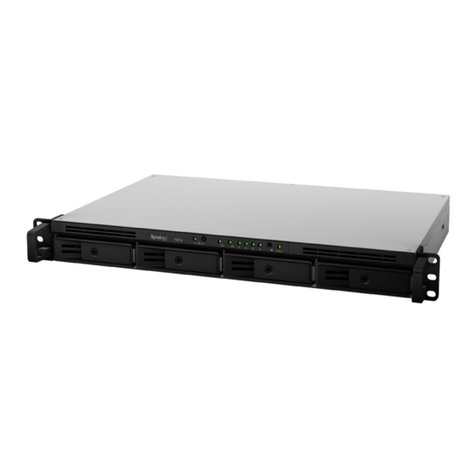
Plug the “suspect” drives or devices into the “Source Inputs”
side of Ditto. All source inputs are write-blocked to prevent
alteration. The source inputs include a USB 2 connection for
USB devices, an RJ45 Gigabit Ethernet connection, a PATA
drive connection, and an eSATA connection for SATA drives
or an eSATA device. The expansion module connection is
used with Ditto expansion modules (available soon).
Use the “Destination Outputs” side of Ditto to store acquired
data. The destination output connections are two eSATA
connections for SATA drives or eSATA devices and an RJ45
Gigabit Ethernet connection.
When you add or remove a drive or enclosure from Ditto, CRU
recommends that you switch the power off to Ditto to avoid
drive damage or data corruption.
The rear of Ditto has an SD card slot and two powering
options: a 12V input for the power supply, and a SATA power
connection. The rear of Ditto also has a hanging hook for
hanging the unit inside the computer case or workstation.
3. Web Browser Interface
Ditto can be congured and operated either from the LCD
interface (see section 9) or through a web browser interface.
3.1 Accessing the Web Browser Interface
a. Plug an Ethernet cable into the Ethernet port on the
“Source Inputs” side of Ditto.
b. Connect the other end of the Ethernet cable to
your network. This usually means plugging it into a
router or hub. In an ofce environment, you may have
a network jack built into your ofce wall.
c. Connect the power cable to the rear of Ditto and to
the provided AC adapter or to SATA power.
d. Turn on Ditto’s power using the switch on the rear
panel. (0 = off, 1 = on)
Hanging hook
Power Input for AC supply
SATA power connection
SD card slot
Power switch
Rear of Unit
Settings
View/Edit >
Source IP Address
10.xxx.xx.xx
PMS711 2cyan
85magenta
76yellow
10.25.12
CRU Mark
Page 4
4. Home Screen
4.1 Action – The Main screen lets you start, abort, and
make notes about the following actions:
4.1.1 Clone Source Disk: Ditto makes an exact
duplicate of the source disk. While cloning the source
disk, the Ditto is also able to hash the source drive using
MD5, SHA-1, or MD5 + SHA-1 and save the hash value.
Ditto can clone to one destination drive or two destination
drives (Mirror feature).
4.1.2 Image Source Disk: Ditto makes a copy of the
source drive into les on to one destination drive or two
destination drives (Mirror feature). E01 and DD are the
two imaging types. While imaging the source disk, the
Ditto also can hash the source disk using MD5, SHA-
1, or MD5 + SHA-1. TIP: For fastest performance we
recommend utilizing EXT4 le system for Windows,
HFS+ for Mac, and XFS for Linux machines.
Note: For the Mirror feature to be shown, both destination
drives must be empty. Tip: A quick way to accomplish
this is to use Ditto to erase each drive using the setting
“Clear Partition Table”.’
4.1.3 Clone and Image Source Disk: This action
simultaneously performs a clone to one destination disk
and perform an image to the second destination disk.
Two destination disks are required for this action.
Note: While running a clone and image, the hash
algorithm saved under clone setting will be used.
4.1.4 Erase Destination Disk: Ditto erases the
destination drive using the pre-congured erasure
method.
4.1.5 Hash Disk: Ditto hashes either the source or the
destination disk (user select) with the hash algorithm
pre-congured. Hash values are saved in the log.
4.1.6 Snapshot Disk: Ditto provides SMART and
HDParm information whenever needed. No clone or
image request needs to be done.
4.1.7 NetView Scan: NetView is a network probing
tool which can be used to discover machines on a
network and even probe them for specic services
which they may be running. This capability may help
an Investigator locate physically hidden computer and
quickly determine whether or not a machine is acting
as a data storage device which may be imaged by Ditto.
See section 4.7.1 for more information about the
NetView Scan feature.

PMS711 2cyan
85magenta
76yellow
10.25.12
CRU Mark

PMS711 2cyan
85magenta
76yellow
10.25.12
CRU Mark
Page 6
4.7.1.1 Info Feature: At any time you may click on the
information icons for a brief description of each individual
setting.
4.7.1.2 Reset Feature: At any time you may click on one
of the Reset icons to load the defaults for that particular
setting.
4.7.1.3 Interface Selection: Select either Source or
Destination from the “Interface” drop-down.
WARNING: When the scan is started the selected
interface will used. This will cause heavy network trafc
load and almost certainly alert your IT department that
the network is under some sort of threat. Ensure that the
selected interface is attached to a controlled and isolated
network.
4.7.1.4 IP Scan Range: By default the last octet of the
IP address of the selected interface will be scanned. You
may change this value and enter a list of IP address, a
range of IP addresses, or a combination of both.
Examples:
1. Range: 10.10.10.0-255
• This will scan the addresses 10.10.10.0 through
10.10.10.255.
2. Range 2: 10.10.10-12.0-255
• This range will scan addresses 10.10.10.0-255,
10.10.11.0-255, and 10.10.12.0-255.
3. List: 10.10.10.1
• This will only scan IP address 10.10.10.1
4. List 2: 10.10.10.2,10.10.10.3
• This will scan only hosts 10.10.10.2 and 10.10.10.3
5. Combo: 10.10.10.1,10.10.10.2,10.10.10.50-100
• This will scan hosts 10.10.10.1, 10.10.10.2 and
hosts 10.10.10.50 through 10.10.10.100.
Remember that the “Reset” button may be used to reset
the IP Scan Range back to its default values.

PMS711 2cyan
85magenta
76yellow
10.25.12
CRU Mark
Page 7
4.7.1.5 Discovery Options: There are 3 optional host
(machine) discovery options available. By default, the
“Ping Echo” should be enough in most cases. Some
machines may be congured to ignore pings and not
respond, so there are 2 other specialized Ping options
which may be useful.
Zero or more of these discovery options may be selected,
and the “Reset” button may be used to reload the defaults.
4.7.1.6 TCP Options: NetView can optionally scan the
specied hosts for open TCP ports. By default Ditto scans
for commonly used services as well as services to which
Ditto may be able to connect, such as NFS, iSCSI, and
Samba.
Checking the box next to “TCP Options” enables this
features and expands more options. Again, the “Reset”
button may be pressed to reset all TCP Options back to
their default values.
Once the TCP Options are expanded we then have more
options.
4.7.1.7 TCP Ports: Similar to the IP Scan Range text box,
the Ports text box can be used to specify lists or ranges
of TCP ports which you would like Ditto to scan. Only the
specied ports will be scanned. Examples:
1. Range: 1-1000
• This will scan TCP ports 1 through 1000
2. List: 22,80
• This will only scan TCP ports 22 (SSH) and 80
(HTTP)
3. Combo: 1-25,80
• This will scan TCP ports 1 through 25 and TCP
port 80.
4.7.1.8 TCP Scan Types: There are two TCP scanning
options. Only one may be selected at a time and a selection
is mandatory. By default the “Syn Scan” is selected,
which is appropriate for most cases. The “Connect Scan”
option may be used if you want Ditto to attempt to create
a system level connection to the specied services. The
“Connect Scan” should only be used by advanced users.
4.7.1.9 UDP Options: NetView can optionally scan
the specied hosts for open UDP ports. By default Ditto
scans for commonly used services as well as services to
which Ditto may be able to connect, such as NFS, iSCSI,
and Samba. UDP port scanning takes much longer than
TCP port scanning due to the connectionless nature of
the UDP protocol, which makes it difcult to determine
whether the packet sent to the port has been lost or the
port is simply not open.
Checking the box next to “UDP Options” enables this
features and expands more options. Again, the “Reset”
button may be pressed to reset all UDP Options back to
their default values.

PMS711 2cyan
85magenta
76yellow
10.25.12
CRU Mark
Page 8
Similar to the IP Scan Range text box, the Ports text box
can be used to specify lists or ranges of UDP ports which
you would like Ditto to scan. Only the specied ports will
be scanned.
Examples:
1. Range: 1-1000
• This will scan UDP ports 1 through 1000
2. List: 69,137
• This will only scan UDP ports 69 (tftp) and
137 (netbios)
3. Combo: 1-25,137
• This will scan UDP ports 1 through 25 and UDP
port 137.
4.7.1.10 Starting the Scan: To start the NetView
scan using the present conguration click on the “Start”
button.
Similar to when other actions run, you should see status
information about the scan. Note that the progress
estimates are VERY crude and still being developed. The
user should see updates every few seconds describing
the current scan being executed, the number of host
discovered, and the progress of the current scan.
4.7.1.11 NetView System Log Results: The system
log will display a summary of the NetView action as it
runs. Once complete you should see the complete scan
system log summary. Displayed will be a link to the
Session (Action) log, arguments used during the scan,
and a “Finished” entry.
4.7.1.12 NetView Session (Action) Log: When you
click on the Session log link in the System Log, then
you will be presented with a NetView session log.
The NetView session log will contain a section which
summaries the discovered hosts. The IP Address, MAC
address, Service, Port #, Protocol and State elds should
all contain information.
The MAC Manufacturer eld may contain the name of
the manufacture associated with the MAC address if
this information can be determined.
The Hostname will be blank if a DNS lookup could not
associate the hosts IP address to a name.
4.7.2 Target Mode: It is possible to mount drives
connected to Ditto on your computers via iSCSI. This can
be very useful if you wish to scan, image, or otherwise
use the disk with 3rd party software.
Using either the source or destination network port works
equally well.

PMS711 2cyan
85magenta
76yellow
10.25.12
CRU Mark

PMS711 2cyan
85magenta
76yellow
10.25.12
CRU Mark
Page 10
After these settings are congured on Ditto and the
iSCSI device, simply ensure that the iSCSI device is
connected to the Source Ethernet port.
On the home screen select “iSCSI Sources” or “iSCSI
Destinations” as appropriate. Input the IP of the iSCSI
device into the Target Host eld. Press “Discover.” Ditto
will detect any IQNs attached to the IP address. Select
the IQN you wish to attach to and press “Add.” Close the
iSCSI pop-up. The iSCSI device has now been added to
the list of disks.
If an iSCSI volume needs to be removed, be sure to select
it from the iSCSI Sources or Destinations window and
press “Remove” before physically removing it from the
network. This will prevent timeout issues where Ditto
attempts to connect to an iSCSI volume that does not
exist.
4.7.3.2 Using NFS/Samba Sources and
Destinations: Ditto can interact with drives or folders
over the network.It can be used to image from the
attached source drives to network destinations via NFS
and Samba Shares.
Ditto comes pre-congured to attach to NFS and Samba
Shares. To connect your Ditto to an NFS or Samba
Share, ensure that the directory is available. For details
on creating an NFS or Samaba Share, contact your IT
Department.
Select either “Source Network” or “Destination Network”
from the Home screen in the web browser interface.
A Network pop-up will open.
Enter the Server name or the path to the NFS or Samba
Share and select “Show Shares.” This will bring up the
available Shares.
Select the appropriate Shares then select “Add.”
The shared drive will now be listed in the Network Paths
window on the Network pop-up.
If Authentication is require for a Samba Share select
Advanced and enter the User Name and Password
Once you verify that that the shared drive is listed,
select “close.”
The Shares will now be available and added to the list
of disks.
To remove the shares, click on “Source Network” or
“Destination Network” as appropriate. Select the iSCSI
or NFS or Samba tab and check the box next to the
share(s) you wish to remove. Click the “Remove” button
to remove that share.

PMS711 2cyan
85magenta
76yellow
10.25.12
CRU Mark
Page 11
5. Congure Screen
5.1 System: Here, you can customize the above system
settings. You can view the current settings under Settings
on the Main screen.
Information that you can adjust includes the default le sys-
tem format of the destination disks and whether or not to
verify the actions Ditto performs. With verication, Ditto
hashes the destination drive and compare the hash value
with the source drive hash value.
You can log disk info (HDPARM and SMART) before running
an action, after running an action, or both. You can also
select ‘off’ to disable logging.
Cogurable hash types include none, MD5, SHA-1, MD5
and SHA-1. Tip: Performance is affected by which hash
type is chosen.
Stealth Mode will turn off all LEDs and LCDs on the Ditto. A
physical ‘Stealth’ switch on the Ditto also serves the same
purpose. HTML Logging will save the action log in HTML
format as well as the default XML format in the image of the
destination drive.
5.2 Network: This screen lets you alter various network
settings. If you are unsure or have questions about changing
your network settings, contact your network administrator.
5.3 Clone Settings: You can alter Ditto’s cloning actions
through both typical and advanced settings.
5.3.1 Typical Clone Settings: Through typical
settings, you can congure the way that Ditto handles
host protected areas (HPAs) and device conguration
overlays (DCOs). The options for handling HPAs and
DCOs are Indicate Only, Temporarily Bypass HPA,
Permanently Unhide HPA, and Permanently Unhide
HPA/DCO. Under Typical settings, you can also select
to ll to the end of the disk, and to reset HPA after a ll.
5.3.2 Advanced Clone Settings: Ditto’s advanced
settings allow you to set the internal buffer size, and to
set the force sector size. You can also choose whether or
not to exit when a bad sector is encountered
5.4 Image: You can customize typical and advanced
settings for both E01 or DD. Click on the E01 or DD tabs
directly under “System.” To select E01 or DD as the image
type, click on the appropriate tab and click “Commit
Changes”.
5.4.1 Congurable E01 Image Settings:
5.4.2 Congurable DD Image Settings:
5.5 Erase:
Ditto allows you to select from various erase modes. See
the following table for the available erase modes. Find out
more about each mode by clicking the “info” button next to
the erase mode selection.

PMS711 2cyan
85magenta
76yellow
10.25.12
CRU Mark
Page 12
Erase Mode Explanation
CLEAR PARTITION TABLE Removes partition table section only
QUICK ERASE Performs single pass writing all zeroes
CUSTOM ERASE Performs 1 to 99 passes (user-select-
able), overwriting with zeroes or a
user-selected pattern
SECURE ERASE N Initiates the drive’s built-in Secure
Erase (Normal) function
SECURE ERASE E Initiates the drive’s built-in Secure
Erase (Enhanced) function
DOD CLEAR Performs US Department of Defense
“Clear” standard
DOD SANITIZE Performs US Department of
Defense “Sanitize” standard
NIST80088 CLEAR “Clear” standard dened by NIST
special publication 800-88
NIST80088 PURGE “Purge” standard dened by NIST
special publication 800-88
Some of these modes come with pre-set specications for
the erase process. With other modes, you can customize
the Pattern (hex or text), HPA/DCO mode (Indicate
Only,Permanently Unhide HPA, and Permanently Unhide
HPA/DCO), Passes (the number of passes to make, used
with custom erase mode only), and Verify (no, minimal,
or yes). When these settings are not available, they will
appear “grayed-out” on the web browser interface.
5.6 Conguring Advanced Hash Settings: The web
browser interface allows you to congure advanced settings
used during the Hash Disk Action.
5.7 Naming: In this menu you can congure how
directories and les will be named for Imaging actions.
The nal directory or lename used in Imaging actions will
use the name that is a series of up to four user selectable
elds.
As shown below, the user selected elds will be displayed
as a template describing the combined current selections.
Additionally, the nal directory and lename will be
displayed using actual values from the Investigation Info
panel (see section 4.2) or values detected by Ditto.
5.7.1 Directory Name Options:
The Create Directory Name section contains four pull
down menus that allow the selection of:
• Case Number - User customized eld from the Home
page Investigation Info panel.
• Description - User customized eld from the Home
page Investigation Info panel.
• Evidence Number - User customized eld from the
Home page Investigation Info panel.
• Investigator - User customized eld from the Home
page Investigation Info panel.
• Source Drive Model Number – Model number of
drive attached to the Source eSATA port.
• Source Drive Unique ID – ID or serial number of the
drive attached to the Source eSATA port.
The Time Stamp eld is shown as grayed out as it is
always begins the directory name.

PMS711 2cyan
85magenta
76yellow
10.25.12
CRU Mark
Page 13
5.7.2 File Name Options: The Create File Name
section contains four pull down menus that allow the
selection of:
• Base File name - User customized eld from the
Home page Investigation Info panel.
• Case Number - User customized eld from the Home
page Investigation Info panel.
• Description - User customized eld from the Home
page Investigation Info panel.
• Evidence Number - User customized eld from the
Home page Investigation Info panel.
• Investigator - User customized eld from the Home
page Investigation Info panel.
• Time Stamp - Time stamp with Year, Month, Day,
Hour, Minute and Second.
• Source Drive Model Number – Model number of
drive attached to the eSATA port.
• Source Drive Unique ID – ID or serial number of
drive attached to the eSATA port.
5.7.3 Imaging with Directory & File Naming:
After choosing options for the Investigation Info and
Naming Directory & Filenames select the Imaging
action. You will notice the new directory and le names
that you created.
6. Admin
The Admin screen allows the administrator to manage
user accounts and assign permission levels for each user.
CRU recommends investigator accounts be set up for best
practices.
Permission levels on the web browser interface are displayed
as FULL, AUTH, or a hyphen. FULL is full access without
a password. AUTH is permission level “Must Authenticate”
and requires a password to make changes. A hyphen is
permission level “none” and permits no access.
To add a new user, simply click “Add User,” enter the user’s
info, and set the permission levels. When nished, select
“Commit Add.”
To update a user’s name, password, or permissions, simply
click on the user name, update the information, and click
“Commit Edits.”
7. Logs
The Logs screen provides information about Ditto’s actions.
The action logs show the timestamp, the type of action
performed, the user, and a link to more information about the
performed action.
When you click the link, the web browser interface displays
the settings that were active when the particular action was
run. You can view information on the system settings, the
source and destination network, the hash, and the action
log. You can also view the source disk HDPARM and SMART
information (if congured in “System Settings.”

PMS711 2cyan
85magenta
76yellow
10.25.12
CRU Mark
Page 14
• Use the link provided to upgrade
• Click on the upgrade link, then download the upgrade
le to the local computer and browse to it to upgrade
• Download the upgrade le to a USB 2.0 device,
and plug that thumb drive into the Ditto. The Ditto
will ask if you want to upgrade. (This does not require
internet connection or connection to the computer)
To upgrade, paste or type the link into the system
maintenance eld. Then select “Firmware Upgrade.” The
web browser interface will then ask you to conrm the
upgrade with the current le. You will then be prompted to
select ”Reboot”. The rmware will then be loaded, and the
rmware’s date is shown next to the “Firmware Upgrade”
button.
“Import Cong” and “Export Cong” save customized
congurations. If the user has a standard setup they can
save it to a le and then import it to any Ditto they connect
to. “Export Cong” saves all the current settings on the
Congure page.
You may also adjust the date and time, reset Ditto to factory
settings, or use “System Verify” to test the rmware and
the Ditto to verify the unit is not compromised or corrupted.
Select “Diagnostics” to create an HTML le containing
information about Ditto’s current state and optionally save
it to the local le system.
9. Usage of Ditto through the LCD
Ditto can work as a stand alone device with no additional
computer required. This can especially be helpful when
working with evidence drives in the eld.
Use the LCD and 4-button navigation interface to clone,
image, erase, or hash a disk. You can also adjust settings,
view information about the drives and dock, or check on
operational status. Which actions and settings can be
accessed from the LCD are determined by the permissions
set. These are assigned by the system administrator in the
web browser interface for the user front panel.
See section 6, Admin.
On the 4-button navigation interface, UP and DOWN allow
scrolling through options, while ENTER selects and BACK
goes back to the previous screen.
Ditto menu consists of the following screens:
9.1 Status Screen
The Status screen is the default screen. It shows the
progress of any current processes or reports the status as
idle. The “Idle” Status screen also lists the current rmware
on Ditto. Examples of various Status screens are shown
below.
Delete or save an action log entry to a location of your
choosing by placing a check next to the entry and selecting
“Delete” or “Save” at the bottom of the screen. If you’re
saving the log, you will be prompted to select either ‘XML’
or ‘HTML’ le format. Once you make your selection, click
“Submit” to save.
Log information is stored on Ditto’s SD card (the SD card slot is
on the rear of Ditto). If no SD card is present, the information in
the log can be viewed only until Ditto is power cycled. When
Ditto is powered down without an SD card, the log becomes
blank. Ditto will recognize any log information already present
on an inserted SD card and make that information available in
the log section of the web interface.
8. Utilities
8.1 System maintenance
Through system maintenance, you can upgrade your Ditto
to the latest rmware. Firmware is usually upgraded to add
new features or increase compatibility.
Firmware upgrades will be made available on CRU’s site
www.cru-inc.com/products/Ditto.php. A link will be
provided to use for upgrading. Upgrade in one of three
ways:

PMS711 2cyan
85magenta
76yellow
10.25.12
CRU Mark
Page 15
Ditto: Idle
Version: 13Mar12a
Up/Dn for Menu >
9.2 Settings
From the Settings screen, you can view or edit the current
Ditto settings.
Settings
View/Edit >
Settings that can be altered include the image type,
erase mode, default format, verication, stealth mode, log
settings, and various network settings. Examples of setting
screens are shown below.
Image Type
E01
Edit>
Erase Mode
Quick Erase
Edit>
Log SMART Info:
On
Edit >
Default Format
NTFS
Edit >
Dest. IP Address:
XX.XX.XX.X
Edit >
Source Network:
Enabled
Edit >
9.3 Disk Info
Disk Info
View >
The Disk Info screen shows all available drives attached to
either the source or destination ports. Each port is shown
only if a drive is connected there.
Press ENTER (View) and then UP or DOWN to view the
following about each connected drive.
• Model number
• Drive size
• File system
Examples of Disk Info screens are shown below:
Destination eSATA-A:
OCZ-VERTEX3
120.0GB
Ext4 le system
Source eSATA:
HTS5410806XXXXX
79.8GB
Fat32 le system
Destination eSATA-B:
Hitachi HTSXXXXX
250.1GB
NTFS le system
9.4 Perform Action
Perform Action
Select >
After you adjust settings to your specications, you are
now ready to put Ditto to work. The Perform Action screen
lets you start or abort any of the Ditto’s functions using
the current settings. With a few punches of the 4-button
navigation interface, you can clone, image, clone + image,
erase or hash a disk.
Clone Disk
< Cancel Continue >
Image Disk
< Cancel Continue >
Erase Disk
< Cancel Continue >
As Ditto performs the action, the status and time left will
display, along with the option to abort the action.
Running Hash
11.8% complete
Time left: 57.2Min
< Abort
Running Hash
1.3% complete
Time left: 1 Hr 4.3 Min
< Abort
Running Erase
12.9% complete
Time left: 1 Hr 3.9 Min
< Abort

PMS711 2cyan
85magenta
76yellow
10.25.12
CRU Mark
Page 16
9.5 Factory Reset
To reset Ditto, press and hold UP, ENTER, and DOWN on the
navigation buttons while powering the unit on.
Ditto will start up as normal, but will the LCD will display
“Preparing Factory Reset.”
****DITTO****
Initializing...
Preparing Factory Reset
****DITTO****
Starting Application
Preparing Factory Reset
You will then be prompted to conrm your choice to reset Ditto.
Factory Reset?
< Cancel Continue >
Press ENTER to continue or BACK to cancel.
You may also use the web browser interface to do a factory
reset. See section 8.1 for more information.

PMS711 2cyan
85magenta
76yellow
10.25.12
CRU Mark
Page 17
10. Technical Specications
Product name: Ditto™ Forensic FieldStation
Data Interface
Speeds:
• Three eSATA ports each SATA II, 3 Gbps
• Two 1000Base-T Ethernet ports both up to 1 Gbps
• PATA/IDE up to 133 MB/s
• USB 2.0 High Speed up to 480 Mbps
Flash Storage: • SD slot supports SD, SDHC (MMC, SD, mini
SD, microSD compatible with adapters)
• Stores Ditto Logs
Drive Types
Supported:
• 2.5” and 3.5” SATA and IDE/PATA hard disk drives
• SATA Solid State Drives
LED Indicators: • Power in 5V/12V
• USB
• Source Network
• IDE
• eSATA
• Expansion
• HPA/DCO
• Destination Network
• eSATA A
• eSATA B
Operating
System
Requirements:
• Windows XP or later
• Mac OS X 10.4.x or higher
• iOS Tablets/phones
• Andriod Tablets/phones
• Most versions of Linux
Browser
compatibility:
• Internet Explorer
• Firefox
• Safari
• Chrome
• Opera
Operating
Humidity:
5% to 95%, non-condensing
Power Switch: 2 position: On / Off
DC Power Input: 40W 12V 3.33A barrel connector (center pin positive)
Alternate power
input:
SATA power input (computer PSU power connectors)
Compliance: • EMI Standard: FCC Part 15 Class A
• CE
• EMC Standard: EN55022, EN55024
• C-Tick
External
Material:
All-aluminum construction
Shipping
Weight:
5 lbs (2.3kg)
Dimensions: 4.92in x 6.77in x 1.72in (125mm x 172mm x 43.7mm)
Write-Blocked
inputs:
• eSATA (SATA),
• PATA/IDE,
• USB 2.0
• Other input types and drive types supported with
Ditto Expansion Modules or drive adapters
Outputs: Two eSATA (SATA) operable single, dual or mirrored
1000Base-T Ethernet
Stealth Mode: Disables all lights (LEDs/LCD)
Interface: Four-line LCD controlled with four soft-touch menu
navigation buttons
Browser-based Ditto interface allows for direct opera-
tion, remote operation, and administration
© 2012-2013 CRU Acquisition Group, LLC. ALL RIGHTS RESERVED
This User Manual contains proprietary content of CRU Acquisition Group, LLC (“CRU”) which is protected by
copyright, trademark, and other intellectual property rights. Use of this User Manual is governed by a license
granted exclusively by CRU (the “License”). Thus, except as otherwise expressly permitted by that License,
no part of this User Manual may be reproduced (by photocopying or otherwise), transmitted, stored (in a data-
base, retrieval system, or otherwise), or otherwise used through any means without the prior express written
permission of CRU. Use of the full Ditto product, including, without limitation, its web interface, is subject to
all of the terms and conditions of this User Manual and the above referenced License.
This product and documentation are provided on a RESTRICTED basis. Use, duplication, or disclosure by
the US Government is subject to restrictions set forth in Paragraph (b) of the Commercial Computer Software
License clause at 48 CFR 52.227-19, as applicable.
CRU™, Ditto® and WeibeTech® (collectively, the “Trademarks”) are trademarks owned by CRU and are pro-
tected under trademark law. Nmap is a registered trademark of Insecure.Com, LLC. This User Manual does
not grant any user of this document any right to use any of the Trademarks.
Product Warranty
CRU warrants this product to be free of signicant defects in material and workmanship for a period of three
years from the original date of purchase. CRU’s warranty is nontransferable and is limited to the original pur-
chaser.
Limitation of Liability
The warranties set forth in this agreement replace all other warranties. CRU expressly disclaims all other
warranties, including but not limited to, the implied warranties of merchantability and tness for a particular
purpose and non-infringement of third-party rights with respect to the documentation and hardware. No CRU
dealer, agent, or employee is authorized to make any modication, extension, or addition to this warranty. In
no event will CRU or its suppliers be liable for any costs of procurement of substitute products or services,
lost prots, loss of information or data, computer malfunction, or any other special, indirect, consequential, or
incidental damages arising in any way out of the sale of, use of, or inability to use any CRU product or service,
even if CRU has been advised of the possibility of such damages. In no case shall CRU’s liability exceed the
actual money paid for the products at issue. CRU reserves the right to make modications and additions to this
product without notice or taking on additional liability.
FCC Compliance Statement: “This device complies with Part 15 of the FCC rules. Operation is subject to the
following two conditions: (1) This device may not cause harmful interference, and (2) this device must accept
any interference received, including interference that may cause undesired operation.”
This equipment has been tested and found to comply with the limits for a Class A digital device, pursuant to
Part 15 of the FCC Rules. These limits are designed to provide reasonable protection against harmful interfer-
ence when the equipment is operated in a commercial environment. This equipment generates, uses, and
can radiate radio frequency energy and, if not installed and used in accordance with the instruction manual,
may cause harmful interference to radio communications. Operation of this equipment in a residential area
is likely to cause harmful interference in which case the user will be required to correct the interference at
this own expense.
In the event that you experience Radio Frequency Interference, you should take the following steps to resolve
the problem:
1) Ensure that the case of your attached drive is grounded.
2) Use a data cable with RFI reducing ferrites on each end.
3) Use a power supply with an RFI reducing ferrite approximately
5 inches from the DC plug.
4) Reorient or relocate the receiving antenna.
FOR OFFICE OR COMMERCIAL USE
Image types
supported:
• DD
• E01
Image/Clone
Output modes:
• Single Drive Image
• Single Drive Clone
• Image and Clone
• Image to mirrored disks
• Clone to mirrored disks
Hash modes
supported:
• None
• MD5
• SHA-1
• MD5 + SHA-1
(Hash types are hardware-accelerated; can hash
during image or clone)
Erase types
supported:
• Clear Partition Table,
• Quick Erase,
• Custom Erase,
• Secure Erase Normal,
• Secure Erase Enhanced,
• DoD Clear,
• DoD Sanitize,
• NIST800-88 Clear,
• NIST800-88 Purge
Warranty: 3 Years
Support Your investment in CRU products is backed up by our
free technical support for the lifetime of the product. If
you need to contact us for any reason, please visit
cru-inc.com/support or call us at 1-800-260-9800 or
+1-360-816-1800.
Table of contents