Cryodex WC786105E User manual

Double Door Stainless Steel Illuminated Cabinet Large
Thank you for purchasing this Double Door Stainless Steel Illuminated Cabinet Large.
Please read the instructions and warnings carefully before use to ensure safe and
satisfactory operation of this product.
Instructions for use
Warnings
IMPORTANT INSTALLATION INFORMATION
THIS IS A CLASS 1 APPLIANCE AND MUST BE CONNECTED TO EARTH
INPUT: 220-240V ac 5A IP RATING: IP44
HAZARDOUS VOLTAGES INSIDE –DO NOT REMOVE ANY COVERS
LAMP TYPE 12V G4 HALOGEN 10W. MAXIMUM TOTAL PER CABINET = 40W
In accordance with Statutory Instrument 2010 No. 2214 - The Building Regulations 2010 the installation of
this product must be either:
carried out by an electrician who is a member of a competent person self-certification scheme who
will certify the work complies with the Building Regulations and you do not need to notify your local
authority, or,
carried out after prior notification to the Local Authority Building Control Department, which has
responsibility for ensuring that the work is inspected and tested.
In accordance with the Building Regulations 2010 Approved Document P, connection to the fixed wiring of
the mains electrical supply must comply with the current revision of the IET Wiring Regulations BS 7671.
IMPORTANT WARRANTY INFORMATION
In accordance with Statutory Instrument 2010 No. 2214 - The Building Regulations 2010 the installer must
give the occupier of the premises in which this product has been installed a certificate to confirm that the
requirements of regulations 4 and 7 have been satisfied within 30 days, or the installation of this product
must be inspected and tested by the Local Authority Building Control Department who will issue a
compliance certificate.
A copy of this certificate may be required for certain warranty claims. Failure to provide a copy of the
certificate may invalidate the warranty.
4. Ensure that the electrical mains supply to which the cabinet is to be connected is turned off. Connect the
flexible mains supply cord on the top of the cabinet to the electrical mains supply in accordance with the
current revision of the IET Wiring Regulations BS 7671. Ensure that the Live (Brown) conductor is
connected to the Live on the electrical mains supply, the Neutral (Blue) conductor is connected to the
Neutral on the electrical mains supply and the Earth (Yellow/Green) conductor is connected to the
Earth/Ground on the electrical mains supply.
Note: Connection of the product to the electrical mains supply must only be carried out by an electrician
who is a member of a competent person self-certification scheme or must be checked by your Local
Authority Building Control Department.

Fixing Pack Contents
(a) Mounting Screws x 4,
(b) Wall Plugs x 4
(c) Plastic Washers x 2
(d) Door Knob Screws x 2
(e) Door Knobs x 2
Tools Required
Drill; 6.5mm masonry drill bit (6.5mm ceramic drill bit optional); Cross-point screwdriver; Pencil; Spirit
level
KEEP DIY TOOLS OUT OF THE REACH OF CHILDREN
Home Safety Advice
Always take care when using a drill, particularly in the bathroom.
Always check for hidden cables and pipework before drilling and take extreme care if there is any
water in the working area. It is advisable to use a residual current circuit breaker (RCCB).
Always wear suitable eye protection when drilling.
If the product is to be fitted on a ceramic tiled wall, a ceramic drill bit should be used. Always
ensure that the drill hole passes through the central tiled area rather than through the grouted
area. To prevent damage to the tile, mask the area around the hole with tape before drilling.
It is recommended that two people fit this product to ensure that it is fitted safely.
Do not strike the product with hard or sharp objects and do not place hot objects against
the glass surfaces.
Do not overload the cabinet. Maximum safe working load is 10kg evenly distributed if
mounted on to a solid wall. If mounted on to a cavity wall reduce the load to 5kg evenly
distributed.
Fixing Instructions
Positioning the Cabinet
1. This cabinet is rated IP44 and must only be installed in the Outside Zones, as shown below in
Fig 1.
(c)
(d)
(e)
(a)
(b)
Fig 1
Hanging the Cabinet
Note: The wall plugs supplied are for use on solid walls only. For cavity walls or plasterboard use
specialist fixings that are available from all good DIY stores.
Fixing Instructions
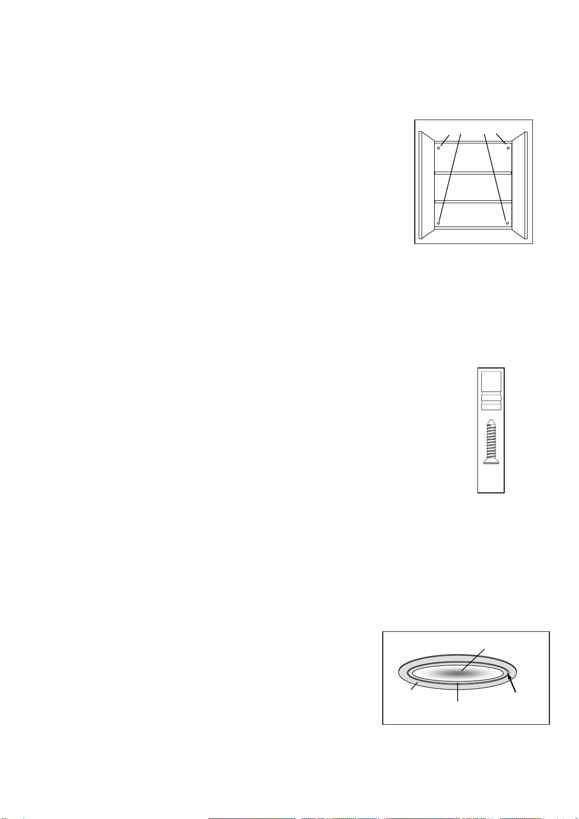
1. Hold the cabinet against the wall in its desired location. Check that the
cabinet is straight and level using a spirit level. Open the doors and
mark the wall through the holes in the back of the cabinet with a pencil
(see Fig 2).
2. Using a 6.5mm masonry drill, drill the holes in the marked positions to a
depth of 26mm and insert the wall plugs into the holes in the wall.
3. Hold the cabinet against the wall and align the holes in the back of the
cabinet with the wall plugs. Insert the mounting screws through the
holes in the back of the cabinet and screw into the wall plugs.
4. Ensure that the domestic electrical mains supply to which the cabinet is to be
connected is turned off. Connect the flexible mains supply cable on the back of the cabinet
to the domestic electrical mains supply ensuring that the Live (Brown) conductor is connected
to the Live on the domestic electrical mains supply, the Neutral (Blue) conductor is connected
to the Neutral on the domestic electrical mains supply and the Earth (Yellow/Green)
conductor is connected to the Earth/Ground on the domestic electrical mains supply. Note:
connection of the product to the domestic electrical mains supply must only be carried
out by a Building Regulations Part P certified electrician or must be checked by your
Local Authority Building Control Department.
5. To attach the handles to the bottom edges of the doors insert the screw into the
bottom of the handle and screw into the pre-drilled hole of the door frame - DO NOT
over-tighten the screws (see fig 3).
Operating Instructions
Cabinet Lights
To turn the cabinet lights on or off simply use the switch located near the top edge of the right
hand side of the cabinet.
Bulb Replacement
CAUTION: The the bulb may become extremely hot. Allow at least 30 minutes after bulb
failure before attempting to replace the bulb.
1. Carefully remove the inner ring and lens from the
lampholder using a small flat screwdriver inserted between
the outer and inner rings (see Fig 4).
2. Carefully remove the failed G4 halogen bulb from the
lampholder (see Fig 4) then insert the pins on the
replacement G4 halogen bulb into the holes in the
lampholder (see Fig 5). Avoid touching the glass
surface of the bulb with bare skin as this may reduce
the life of the bulb. Only use 12V 10W G4 Halogen bulbs.
Mounting holes
Fig 2
Outer ring
Inner ring
Fig 4
Lens
Insert
screwdriver
here
Fig 3
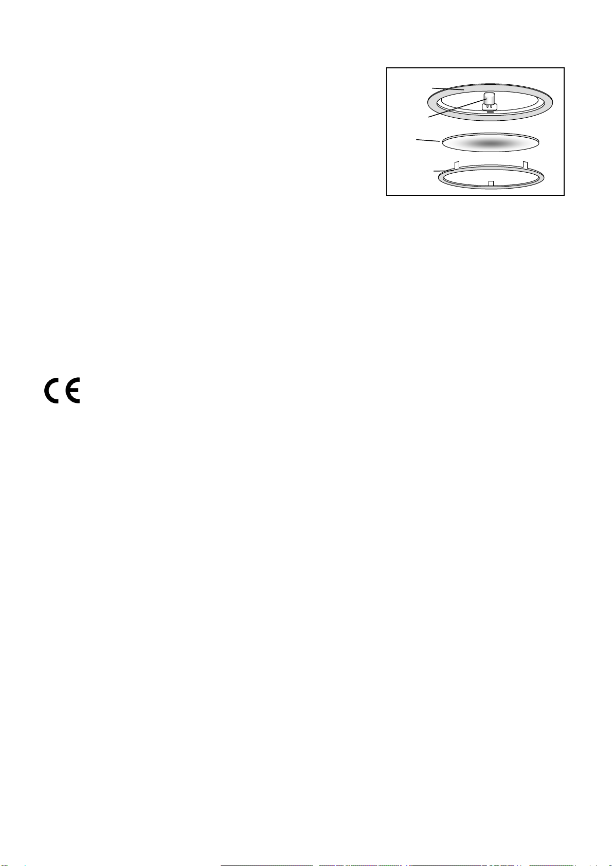
3. Carefully insert the glass lens into the inner ring and align the
three clips on the inner ring with the slots in the lampholder.
Gently press around the inner ring until it is flush with the
outer ring (see Fig 4). Avoid using excessive force as this
may damage the lens or cause injury.
4. Please dispose of failed bulbs through appropriate waste
collection facilities.
Product Care
Please retain this information leaflet for future reference.
To retain the best quality finish, clean product regularly with a soft cloth and mild detergents. Do
not use abrasive or chemical cleaners as these will damage the product. Spray cleaning liquids
onto the cloth and not directly onto the glass.
Do not position glass components in close contact with a heat source.
Markings
This product complies with the requirements of
European Parliament/Council Directive 73/23/EC the Low Voltage Directive amended by
European Parliament/Council Directive 93/68/EEC.
European Parliament/Council Directive 89/336/EEC on electromagnetic compatibility
(EMC Directive) amended by 91/263/EEC, 92/31/EEC and 93/68/EEC.
Applicable Standards with amendments:
BS EN 55-015
BS EN 61547
BS EN 61000-3-2
BS EN 61000-3-3
BS EN 60598-2-1
BS EN 61558-2-5
CAB 030 R04
Outer ring
G4 Bulb
Lens
Inner ring
Fig 5
Table of contents
Popular Indoor Furnishing manuals by other brands

JWA
JWA HARMON 74690 Assembly instruction

Design Within Reach
Design Within Reach MIN TABLE 690461 Assembly instructions

Next
Next 453471 Assembly instructions

OVE
OVE TAHOE III-60 installation manual

burgbad
burgbad Finca M1012 Fitting instructions

Seville Classics
Seville Classics 15896 Assembly instructions and rules


