CryptoTelecom S-160 User manual

1
Network A/V Server S-160
User’s Manual
(Version1.0)

2
Introduction
¾The S-160 is a 4 channel video server with a built-in MPEG-4 CODEC and Streaming Server. The main
feature of the MPEG-4 CODEC and the built-in Streaming Server allows you to monitor real time images from
remote locations via Internet. S-160 features a Sensor Input, Relay Output, RS232C port that is designed to
control the functions of select pan/tilt/zoom cameras. S-160 supports both Static IP and Dynamic IP, and
can change the Communication Port resulting in one IP address supporting multiple S-160 video servers. In
summary, S-160system provides multiple access/control options to the user.
The examples of access/controls are as follows:
¾To get SMS message through Mobile Phone and E-mail message from PC when events occur.
¾To record Event in FTP server installed in remote place or S-160.
¾To search / delete / down-load / replay the recorded video.
¾To support various wireless devices such as Mobile Phone, PDA to see real time Video in Wireless Internet
handset.
For more information or inquiry, please contact us to the followings ;
Home Page : www.cryptotelecom.com
E-mail : [email protected]
Telephone ; 82-2-596-1331
Fax : 82-2-596-3707
Address : 5 floor, Seungwon Bldg.,810-9, Bangbae-dong, Seocho-gu, Seoul, 137-064, Korea
Software, Server and service may be charged according to change of policy or may be stopped
without prior notification. Appearance, function and specification may be changed without prior
notification. Our company assumes no responsibility for visible or invisible loss resulted from
changes in policy or products.

3
IMPORTANT NOTES
•Before operating the Vaddio StreamVIEW, please read the entire manual thoroughly. The system was
designed, built and tested for use indoors, and with the provided power supply and cabling. The use of a
power supply other than the one provided or outdoor operation has not been tested and could damage the
unit and/or create a potentially unsafe operating condition.
•Do not operate the S-160if the unit has been dropped or damaged. In this case, a Vaddio technician must
examine the product before operating.
•To reduce the risk of electric shock, do not immerse in water or other liquids and avoid extremely humid
conditions.
•Do not attempt to take the S-160 apart. There are no user-serviceable components inside.
•Do not use this product in connection with life safety or life monitoring related devices, i.e., medical
apparatus.
•Do not operate the S-160under the following conditions for any circumstance:
•Temperatures above 40°C (104°F)
•Temperatures below 0°C (32°F)
•High humidity, condensing or wet environments
•Dusty environments
•In inclement weather or under severe vibration

4
Contents
1. FEATURE …………………………………………………………………………….………7
1.1.UNPACKING…………………………………………………………………………………………..……….…7
1.2. EXTERNAL VIEW……………………………………………………………………………………..……..…...7
1.2.1.Front view …………………………………………………………. …………………………………………...7
1.2.2.Rear view ………………………………………………………. ………………………...………… …..……...8
2. INSTALLATION AND VIDEO CHECK……………………………………………………10
2.1.INSTALLATION…………………………………………………………………………………………….….…10
2.2.VIDEO CHECK…………………………………………………………………………………….……………10
3. BASIC SETTING……………………………………………………………………………16
3.1.CHECK NETWORK AND INSTALLATION TYPE……………………………………………………….….………16
3.2.INSTALLATION WITHOUT IP SHARING DEVICE (ROUTER)……………………………………………..……….16
3.2.1.Static IP Setup………………………………………………………………………………………….………..16
3.2.2.Dynamic IP Setup………………………………………………………………..………………….……..……20
3.3.INSTALLATION WITH IPSHARING DEVICE (ROUTER)……………………………………………….………...22
3.4.CAUTIONS…………………………………………………………………………………………….……….26
4. EXPERT SETTING…………………………………………………………………………28
4.1.GENERAL SETTING……………………………………………………………………………………..……..30
4.1.1.Title Setting………………………………………………………………………………..……..……...………30
4.1.2.Administrator’s ID and Password Change………………………………………………..………………….31
4.1.3.User Registration…………………………………………………………………………………….…………31
4.1.4.User List and Delete…………………………………………………………………………………...……….31
4.1.5.Skip Login (Automatic Monitoring) ………………………………………………………….….…………..32
4.1.6.Time Zone Setting ……………………………………………………………………………..………………32
4.1.7.Set Download Route of Plug-in Type ActiveX……………………………………..………………………...33
4.1.8.Select Language………………………………………………………………………………..………..……..33
4.2.NETWORK SETTING……………………………………………………………………………….…….……33
4.3.VIDEO &AUDIO SETTING……………………………………………………………………………..………34
4.3.1.Video Setting…………………………………………………….……………………….……………………..34
4.3.2.Audio Setting…………………………………………………………….…………………………….………..37
4.4.COLOR SETTING……………………………………………………………………..……………………….38
4.5.ALARM SETTING………………………………………………………………………………..…………….39
4.5.1.Alarm Event Setting……………………………………………………………………………..……………..39
4.5.2.Alarm Event Test…………………………………………………………………..…………..……………….40
4.6.DIO SETTING……………………………………………………………………………………..………….41
4.7.RS232C SETTING………………………………………………………………………………..………….42
4.8.PRESET SETTING………………………………………………………………………………….………...44

5
4.9.HOMEPAGE UPDATE………………………………………………………………………………………...45
4.10.FIRMWARE UPDATE……………………………………………………………………………….….……45
4.10.1.Remote Upgrade………………………………………………………………………………...….………45
4.10.2.System Re-booting………………………………………………………..…………………..……………47
5. BASIC USE………………………………………………………………….……………49
5.1.USE OF WEB VIEWER…………………………………………………………………….………………..49
5.2.USE OF IPSETTING UTILITY……………………………………………………………….………………51
5.3.USE OF PIMASERVER…………………………………………………………………….………………54
5.3.1.User Registration………………………………………………………….………………..……………….54
5.3.2.Camera Registration…………………………………………..……………………….……..…………….57
5.3.3.List of Camera………………………………………………………………………….……….…………...58
5.3.4.Change of User’s Information…………………………………………………………………….………..60
5.3.5. Search Camera………………………………………………….……………..………………….……….61
5.4.USE OF RELAY…………………………………………………………………………………….……….62
5.5.USE OF SENSOR…………………………………………………………………………………….……..63
5.6.SEE AND CONTROL OF STILL IMAGE IN MOBILE OR PDA ………………………………………….……..63
5.6.1.WAP2.0 (HTML) …………………………………………………..………………………….……….…….63
5.6.2.PDA(WinCE) ………………………………………………………………………………………...………66
5.7.USE OF PROPRIETARY VIEWER(MPEG4 COMMUNICATOR)……………………………………….…….67
5.7.1.Required Specification of PC and OS…………………………………………………………….…..…..67
5.7.2.Supported O/S…………………………………………………………………………………..…….…….67
5.7.3.Program Installation………………………………………………………………………….…….……….68
5.7.4.Use of Program……………………………………………………..……………….………….…………..71
5.7.4.1.Viewer Screen……………………………………………………………………….….……….…………..………71
5.7.4.2.General Setting Menu …………………………………………………………………………...…………..73
5.7.4.3.S-160 Connection……………………………………………………………………………………….…..………74
5.7.4.4.Play of Recorded File…………………………………………………………………………………….…....……76
5.7.4.5.Use of Pop-up Menu…………………………………………………………………………………….…..….…..77
6. NETWORK ENVIRONMENTS…………………………………………………….…….79
7. APPENDIX………………………………………………………………………….……81

6
1. Feature
7
1. Feature
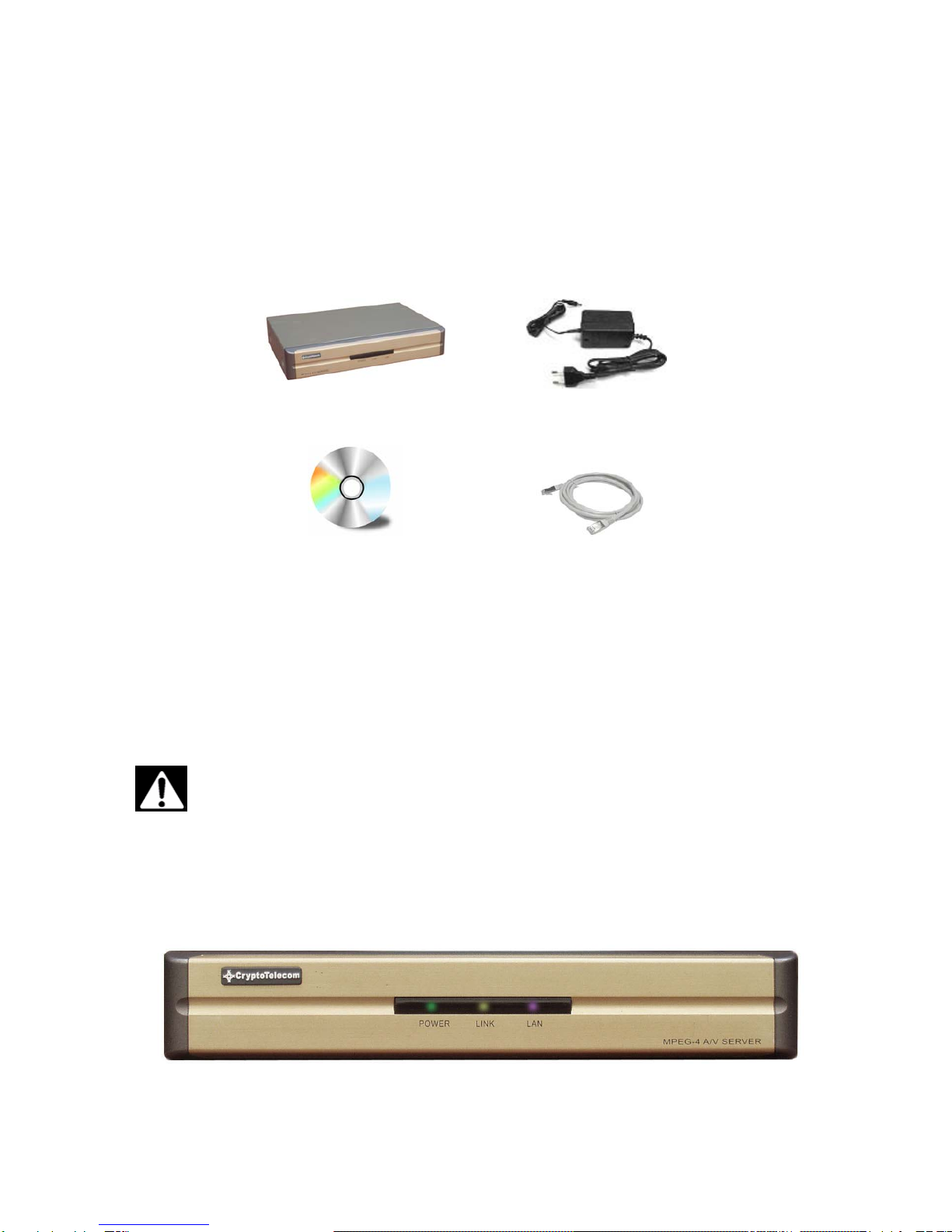
1.1 Unpacking
Carefully remove the product and all of the parts from the packaging. Unpack and identify the following parts:
S-160 Power Adapter
Software CD Cross Cable
The content of the packaging includes, S-160 Main Unit, Power supply, User Manual, Software CD, Cross Cable
(for installation only). Please check contents before starting installation. Be sure to use the provided power
supply for the S-160. The Cross Cable is used only for Pre-View of Video before set-up and change of Network
Information.
Use only the power supply provided with the S-160 system.
Use of any unauthorized power supply will void any and all warranties.
1.2 External View
1.2.1 Front view
①
②
③
8
1) POWER : Light on when power is supplied.
2) LINK : Light on when LAN Cable is connected to S-160.
3) LAN : Light on when connected to Network.
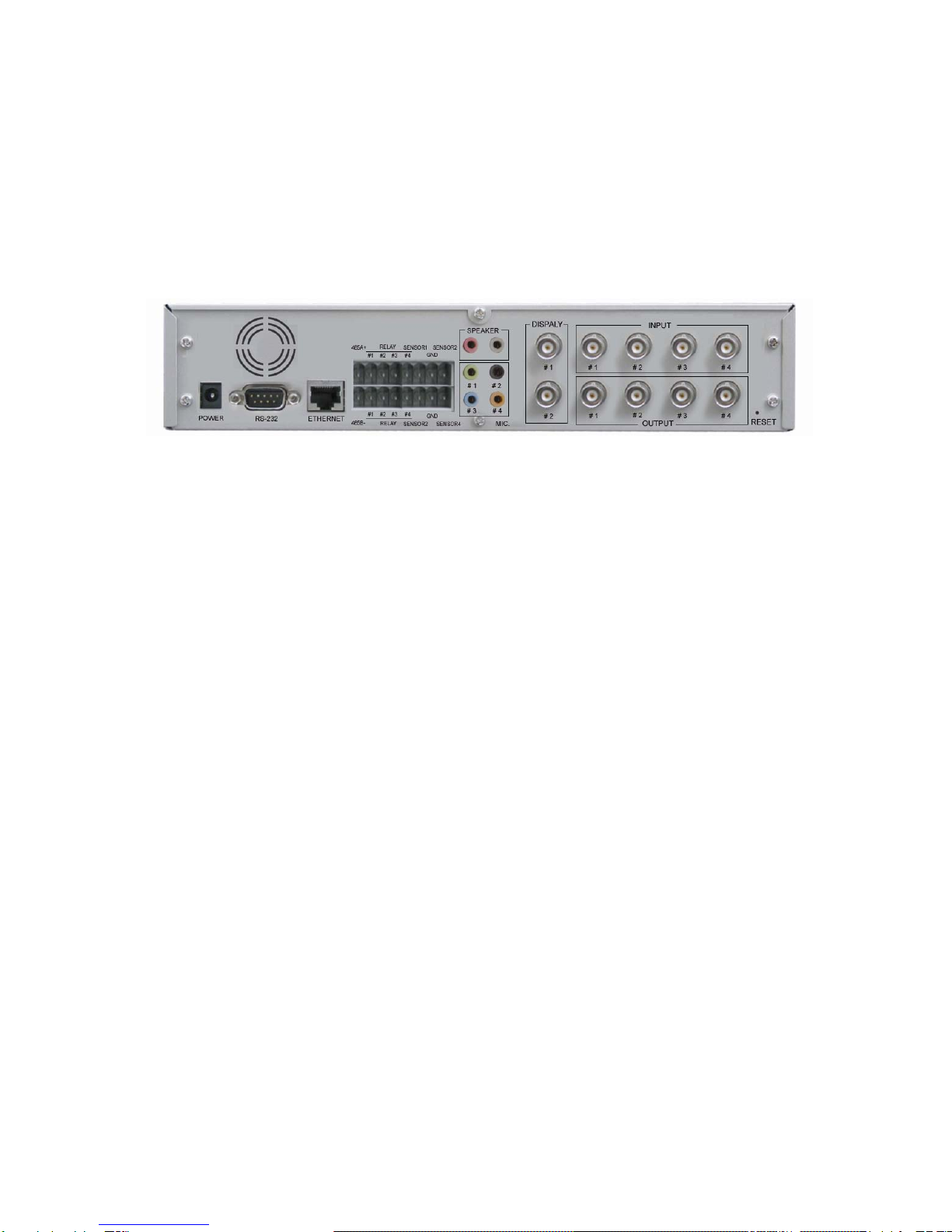
1.2.2 Rear view
1) Power Supply : Excusive (provided) Adapter only
2) Micro Phone Port : To connect Microphone
3) Speaker Port : To connect Speaker
4) Relay Output : Output port with embedded Relay.
5) Sensor Input : Sensor Input port, to be set in Inner Setting and to be used without regard to N/C or N/O
6) RS485 Port : Input / Output Port of RS485
7) Serial Port : To control of Pan/Tilt/Zoom of Camera and connect to PLC or outer Devices (RS232)
8) Video In : Input port to connect with signal output from Camera, VTR, Quad, DVR
9) Video Out : Output of the same video signal that put into the Video Input Port.
10) LAN : LAN Cable port for Internet to connect to Internet
11) Hardware Reset : To initialize basic setting. Push and hold for seconds to start initialization.
① ②
③④ ⑤⑥
⑦
⑧
⑨
⑩
⑪
⑫

9
2. Installation and Video Check
10
2. Installation and Video Check
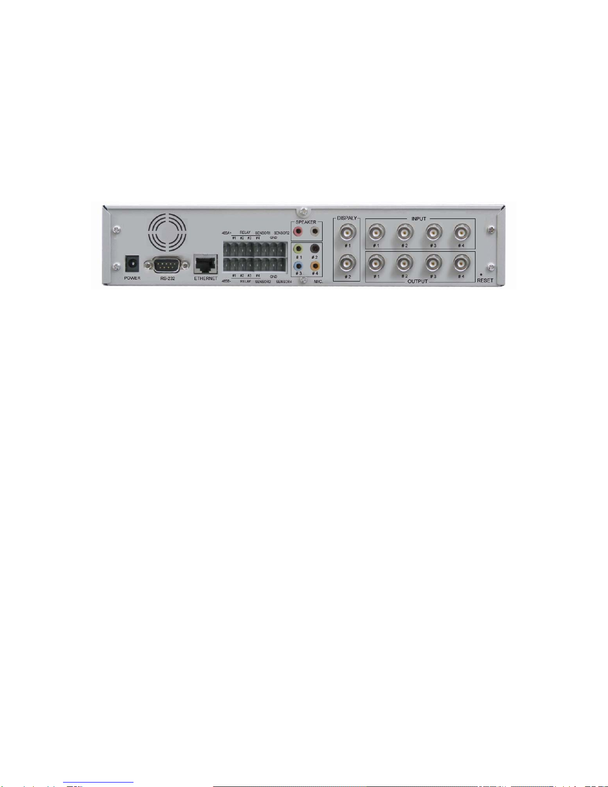
2.1 Installation
On the assumption that User PC and S-160 Sever is used under static IP, and S-160 is to be directly connected
with User PC or Local Network, the installation procedure is to be ;
Pic. 2―1 Rear View
1) Connect Camera and StreamVIEW with Video Cable (8 of [Pic.2-1]).
2) If connecting a Pan/Tilt Camera for control, connect Cable into RS232 Port (7 of [2-1]) or RS485 Port (6 of
[2-1]).
3) Connect StreamVIEW and PC with LAN Cable (Cross Cable) (10 of [2-1])
4) Turn on Camera and StreamVIEW (Use provided power supply only) (1 of [2-1])
5) Wait about 2 minutes after powering up the StreamVIEW, and then the LINK LED shows that the System
has been booted normally.
2.2 Video Check
Basic network setting value of S-160 is to be ;
9IP Address : 192.168.1.8
9Subnet Mask : 255.255.255.0
9Gateway : 192.168.1.1
To connect S-160 in user’s PC, change the setting value of PC network environment.
⑪
① ②
③④ ⑤⑥
⑦
⑧
⑨
⑩
⑪
Table of contents


