Crystal Mini 40 User manual

INSTALLATION AND
USER MANUAL
for your heat pump
Crystal Mini 40

1

W
arning
2
works.
This heat pump contains a flammable refrigerant R32.
Any intervention on the refrigerant circuit is prohibited without a valid autho-
rization.
Before working on the refrigerant circuit, the following precautions are neces-
sary for safe work.
1. Work procedure
The work must be carried out according to a controlled procedure, in order to mini-
mize the risk of presence of flammable gases or vapors during the execution of the
2. General work area
All persons in the area must be informed of the nature of the work in progress. Avoid working in a confined
area. The area around the work area should be divided, secured and special attention should be paid to
nearby sources of flame or heat.
3. Verification of the presence of refrigerant
The area should be checked with a suitable refrigerant detector before and during work to ensure that
there is no potentially flammable gas. Make sure that the leak detection equipment used is suitable for
flammable refrigerants, ie it does not produce sparks, is properly sealed or has internalsafety.
4. Presence of fire extinguisher
If hot work is to be performed on the refrigeration equipment or any associated part, appropriate fire extin-
guishing equipment must be available. Install a dry powder or CO2 fire extinguisher near the work area.
5. No source of flame, heat or spark
It is totally forbidden to use a source of heat, flame or spark in the direct vicinity of one or more parts or
pipes containing or having contained a flammable refrigerant. All sources of ignition, including smoking,
must be sufficiently far from the place of installation, repair, removal and disposal, during which time a
flammable refrigerant may be released into the surrounding area. Before starting work, the environment
of the equipment should be checked to ensure that there is no risk of flammability. «No smoking» signs
must be posted.
6. Ventilated area
Make sure the area is in the open air or is properly ventilated before working on the system orperforming
hot work. Some ventilation must be maintained during the duration of the work.
7. Controls of refrigeration equipment
When electrical components are replaced, they must be suitable for the intended purpose and the appro-
priate specifications. Only the parts of the manufacturer can be used. If in doubt, consult the technical
service of the manufacturer.
The following controls should be applied to installations using flammable refrigerants:
- The size of the load is in accordance with the size of the room in which the rooms containing the
refrigerant are installed;
- Ventilation and air vents work properly and are not obstructed;
- If an indirect refrigeration circuit is used, the secondary circuit must also be checked.
- The marking on the equipment remains visible and legible. Illegible marks and signs must be corrected;
- Refrigeration pipes or components are installed in a position where they are unlikely to be exposed to a
substance that could corrode components containing refrigerant
8. Verification of electrical appliances
Repair and maintenance of electrical components must include initial safety checks and component
inspection procedures. If there is a defect that could compromise safety, no power supply should be
connected to the circuit until the problem is resolved.
Initial security checks must include:
•That the capacitors are discharged: this must be done in a safe way to avoid the possibility of sparks;
•No electrical components or wiring are exposed during loading, recovery or purging of the refrigerant
gas system;
•There is continuity of grounding.

T
hank you
3
Dear Customer,
Thank you for your purchase and for your confidence in our products.
These are the result of many years of research in the field of design and production of heat pumps
for swimming pools. Our aim is to provide you with an exceptional high performance quality product.
We have produced this manual with the utmost care so that you get maximum benefit from your
heat pump.

4
! PLEASE READ CAREFULLY
These installation instructions are an integral part of the product.
They must be given to the installer and retained by the user.
If the manual is lost, please consult the website:
The instructions and recommendations contained in this manual should be read carefully and
understood since they provide valuable information concerning the heat pump’s safe handling and
operation. Keep this manual in an accessible place for easy future reference.
Installation must be carried out by a qualified professional person in accordance with current
regulations and the manufacturer’s instructions. An installation error may cause physical injury
to persons or animals as well as mechanical damage for which the manufacturer can under no
circumstances be held responsible.
After unpacking the heat pump, please check the contents in order to report any damage.
Prior to connecting the heat pump, ensure that the information provided in this manual is compat-
ible with the actual installation conditions and does not exceed the maximum limits authorized for
this particular product.
In the event of a defect and/or malfunction of the heat pump, the electricity supply must be
disconnected and no attempt made to repair the fault.
Repairs must be undertaken only by an authorized technical service organization using original
replacement parts. Failure to comply with the above-mentioned clauses may have an adverse
effect on the heat pump’s safe operation.
Toguarantee the heat pump’s efficiency and satisfactory operation, it is important to ensure its
regular maintenance in accordance with the instructions provided.
If the heat pump is sold or transferred, always make sure that all technical documentation is
transmitted with the equipment to the new owner.
This heat pump is designed for heating a swimming pool/Hot Tub or Pond. Any other use mustbe
considered as being inappropriate, incorrect or even hazardous.
Any contractual or non-contractual liability of the manufacturer/distributor shall be deemed null
and void for damage caused by installation or operational errors, or due to non-compliance
with the instructions provided in this manual or with current installation norms applicable to the
equipment covered by this document.

Contents
5
1. General..........................................................................................................................................6
1.1 General Terms ofDelivery................................................................................................ 6
1.2 Safetyinstructions............................................................................................................ 6
1.3 Watertreatment ..............................................................................................................7
2. Description...................................................................................................................................8
2.1 Packagecontents ............................................................................................................8
2.2 Generalcharacteristics.....................................................................................................8
2.3 Technicalspecifications ...................................................................................................9
2.4 Unit dimensions.............................................................................................................10
2.5 Explodedview................................................................................................................11
3. Installation..................................................................................................................................12
3.1 Location ................................................................................................................................12
3.2 Installationlayout............................................................................................................13
3.3 Hydraulic connection.......................................................................................................13
3.4 Electricalconnection.......................................................................................................13
4. Use.......................................................................................................................................14
4.1 Controlpanel...................................................................................................................14
4.2 Operating modeselector.................................................................................................14
4.3 Heating Mode .................................................................................................................15
4.4 Cooling Mode .................................................................................................................16
4.5 Silent Mode.....................................................................................................................17
4.6 Auto Mode......................................................................................................................17
4.7 Status values and advancedsettings...............................................................................18
5.Operation.............................................................................................................................20
5.1 Operation........................................................................................................................20
6.Maintenance and servicing................................................................................................ 21
6.1 Maintenance, servicing and winter storage......................................................................21
7.Repairs................................................................................................................................ 22
7.1 Breakdowns and faults....................................................................................................22
7.2 List of faults. ...................................................................................................................23
8.Recycling ............................................................................................................................24
8.1 Recycling the heat pump................................................................................................24
A.Appendices........................................................................................................................................25
A.1 Wiring diagrams........................................................................................................................ 25

1. General
6
All equipment, even if shipped ‘free of carriage and packing’, is dispatched at the consignee’s own
risk.
The person responsible for receiving the equipment must carry out a visual inspection to identify
any damage to the heat pump during transport (refrigerant system, body panels, electrical control
box, frame). He/she must note down on the carrier’s delivery note any remarks concerning
damage caused during transport and confirm them to the carrier by registered letter within 48
hours.
The equipment must always be stored and transported vertically on a pallet and in its original
packaging. If it is stored or transported horizontally, wait at least 24 hours before switching it on.
During installation and servicing
Only a qualified person may undertake installation, start-up, servicing and repairs, in compliance
with current standards.
Before operating or undertaking any work on the equipment (installation, commissioning, usage,
servicing), the person responsible must be aware of all the instructions in the heat pump’s
installation manual as well as the technical specifications
Under no circumstances install the equipment close to a source of heat, combustible materials or
a building’s air intake.
If installation is not in a location with restricted access, a heat pump protective grille must be fitted
Toavoid severe burns, do not walk on pipework during installation, repairs or maintenance.
Toavoid severe burns, prior to any work on the refrigerant system, turn off the heat pump and wait
several minutes before placing temperature and pressure sensors.
Check the refrigerant level when servicing the heat pump.
Check that the high and low pressure switches are correctly connected to the refrigerant system
and that they turn off the electrical circuit if tripped during the equipment’s annual leakage
inspection.
Check that there is no trace of corrosion or oil stains around the refrigerant components.
WARNING :
Please
read
carefully
the
safety
instructions
before
using
the
equipment.
The
following
instructions
are
essential
for
safety
so
please
strictly
comply
with
them.
1.
2
Safety instructions
1.
1
General Terms of Delivery

1. General
7
During use
Toavoid serious injuries, never touch the fan when it isoperating.
Keep the heat pump out of the reach of children to avoid serious injuries caused by the heat
exchanger’s blades.
Never start the equipment if there is no water in the pool or if the circulating pump is stopped.
Check the water flow rate every month and clean the filter ifnecessary.
During cleaning
Switch off the equipment’s electricity supply.
Close the water inlet and outletvalves.
Do not insert anything into the air or water intakes or outlets.
Do not rinse the equipment with water
Rinse onlythe titanium with water
During repairs
Carry out work on the refrigerant system in accordance with current safetyregulations.
Brazing should be performed by a qualified welder.
When replacing a defective refrigerant component, use only parts certified by our technical
department.
When replacing pipework, only copper pipes conforming to Standard NF EN12735-1 may beused
for repairs.
When pressure-testing to detectleaks:
Toavoid the risks of fire or explosion, never use oxygen or dry air.
Use dehydrated nitrogen or a mixture of nitrogen andrefrigerant.
The low and high side test pressure must not exceed 42bar.
heat pumps for swimming pools can be used with all types of water treatmentsystems.
Nevertheless, it is essential that the treatment system (chlorine, pH, bromine and/or salt chlorina-
tor metering pumps) is installed after the heat pump in the hydraulic circuit.
To avoid any deterioration to the heat pump, the water’s pH must be maintained between
6.9 and 8.0.
1.3
W
ater treatment

2.
Description
8
ν Crystal Heat pump - Mini 40 Turbo R32
ν 2 hydraulic inlet/outlet connectors 32/38mm diameter
ν This installation and user manual
ν 4 anti-vibration pads
A heat pump has the following features:
CE certification and complies with the RoHS European directive
High performance with up to 90% energy savings compared to a conventional heating
system.
Clean, efficient and environmentally friendly R32 refrigerant
Reliable high output leading brand compressor.
Wide hydrophilic aluminum evaporator for use at low temperatures.
User-friendly intuitive control panel.
Heavy duty shell, anti-UV treated and easy to maintain.
Designed to be silent.
2.
2
General characteristics
2.
1
Package contents

2.
Description
9
Crystal Mini 40
Advised poolvolume
m³
20~25
Heating temperaturerange
℃
25~45
Cooling temperaturerange
℃
5~28
Auto mode temperature range
℃
5~43
Operatingrange
℃
-20~43
Air 26℃ Water 26℃
capacity(KW)
4.25~2.10
powerinput(KW)
0.73~0.18
Currentvalue(A)
3.24~0.79
COP
11.60~5.82
Air 15℃ Water 26℃
capacity(KW)
3.15~1.22
powerinput(KW)
0.75~0.18
Currentvalue(A)
3.26~0.79
COP
6.75~4.20
Air 35℃ Water 27℃
capacity(KW)
2.58~0.85
powerinput(KW)
0.75~0.68
Currentvalue(A)
3.26~0.21
EER
4.05~3.44
Air -15°C Water26℃
Capacity(KW)
1.42~0.55
Powerinput(KW)
0.713~0.171
Inputcurrent(A)
3.087~0.743
COP
3.22~1.99
Air -20°C Water26°C
Capacity(KW)
0.79~0.31
Powerinput(KW)
0.675~0.162
Inputcurrent(A)
2.913~0.704
COP
1.91~1.17
powersupply
220-240V / ~/50Hz
max powerinput
KW
1.5
max current
A
6.65
water flow-Min/Max
m³/h
0.9/3.6
Refrigerantvolume
R32/0.30kg
Min pressure/maxpressure
1.5/4.15MPa
unit netdimensions(mm)
400x280x385
packagedimensions(mm)
460x370x415
net weight kg
20
gross weightkg
22
noise at 10m
<35dB(A)
compressor brand
GMCC
Condensertype
TitaniumTube
water prooflevel
IPX4
Loss charge(mCE)
0.8
The technical specifications of our heat pumps are provided for information purposes only. We reserve the
right to make changes without prior notice.
2.
3
Technical specification

2.
Description
10
Dimensions in mm
Crystal Mini 40
A
385
B
420
C
290
D
52
E
180
2.
4
Unit dimensions
A
D
E
B
C
2.
Description
11
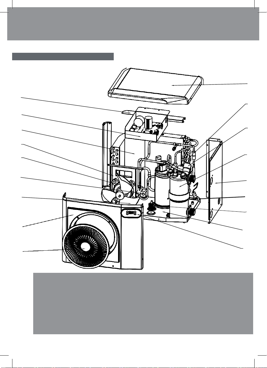
1. Fan protective grille
2. Front panel
3. Fan blade
4. 4-way valve
5. Fan motor
6. Fan support
7. Evaporator
8. Electrical control box
9. Mounting frame
10. Top panel
11. Compressor
12. Water Flow Switch
13. Heat exchanger
14.Left side panel
15. Electric base frame heating
16. Electric crankshaft heating
17. Base frame
18. Control panel
9
8
7
6
5
4
3
10
11
12
13
2
1
14
15
16
17
18
2.5
Exploding view
3. Installation
12
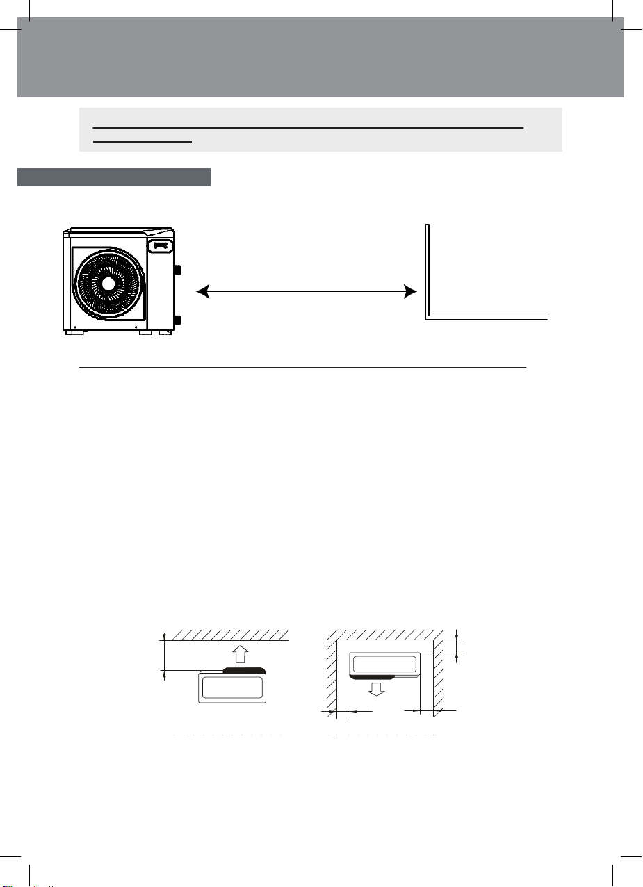
The heat pump should be located at least 2.5 meter away from the swimming pool.
Please comply with the following rules concerning the choice of heat pump location.
1. The unit’s future location must be easily accessible for convenient operation and maintenance.
2. It must be installed on the ground, laid ideally on a level concrete base . Ensure that the floor
is sufficiently stable and can support the weight of the unit
3. Check that the unit is properly ventilated, that the air outlet is not facing the windows of neigh-
boring buildings and that the exhaust air cannot return. In addition, provide sufficient space
around the unit for servicing and maintenance operations.
4. The unit must not be installed in an area exposed to oil, flammable gases, corrosiveproducts,
sulfurous compounds or close to high frequency equipment.
5. Toprevent mud splashes, do not install the unit near a road or track.
6. Toavoid causing nuisance to neighbors, make sure the unit is installed so that it is positioned
towards the area that is least sensitive to noise.
7. Keep the unit as much as possible out of the reach of children.
≥30
≥30
Dimensions in cm
Place nothing less than 1,50 m in front of the heat pump.
Leave 30 cm of empty space around the sides and rear of the heat pump.
Do not leave any obstacle above or in front of the unit!
Pool
>2.5m
3.
1
Location
The
heat
pump
is
very
easy
to
install,
only
water
and
power
need
to
be
connected
during installation.
≥
150
3. Installation
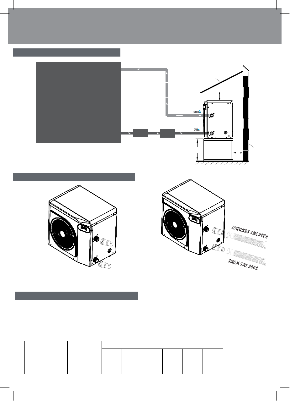
13
TOWARDS THE POOL
Snow tent
POOL
≥30cm
Filtration
Pump
FROM THE POOL
The filter located upstream of the heat pump must be regularly
backwashed so that the water in the system is clean, thus avoiding
the operational problems associated with dirt or clogging in the filter.
50-80cm ≥30cm
subgrade
wall
Step 1
Screw the connectors to the heat pump Step 2
Connect the water outlet pipe and the water intake pipe
The heat pump electrical plug integrates a 10mA differential circuit breaker.
Before connecting your heat pump, please ensure that the plug is
connected to the ground.
The filter pump should function at the same time as the heat pump.
Therefore, you need to connect them to the same electrical circuit.
Model
max current(A)
maximum length of the wire(m)
Refrigerant
2
1.0mm
2
1.5mm
2
2.5mm
2
4mm
2
6mm
2
10mm
Crystal Mini 40
6.65
36
52
88
142
213
371
R32
3.
4
Electrical connection
3.
3
Hydraulic connection
3.
2
Installation layout

4.
Use
14
1. Mode button
2. Heating mode indicator
3. Cooling/Defrost mode indicator
4. Silent mode indicator
5. Auto mode indicator
6. Wifi indicator
7. Increase Temp. button
8. Decrease Temp. button
9. ON/OFF button
Prior to setting your required temperature, you must first select an operating mode for your control
panel:
Heating Mode
Select the heating mode for the heat pump to heat
the water in your pool.
Cooling Mode
Select the cooling mode for the heat pump to cool
the water in your pool.
Silent Mode
Select the heating mode for the heat pump to heat
the water in your pool.
Auto Mode
automatic cooling or heating according to the set
temperature.
Wifi
Wifi function enabled
Before starting, ensure that the filtration pump is working and that water is circulating
through
the heat
pump.
4.2
erat
m
e
se
ect
r
4.1
12 3 4 5 6 7
9
8

4.
Use
15
Step 1 : Press to switch on yourpump.
Step 2 : Press to switch from onemode to another until the heating mode is displayed.
Step 3 : Using buttons and select the required
temperature. EXAMPLE:
If the current temperature is 18.8°C, default setting temperature is 27°required temperature is 30°
C.
Current water temperature Required water temperature
Useful information about how the heating modeoperates
When the incoming water temperature is less than or equal to the required temperature (set point
temperature) -X°C, the heat pump will switch to heating mode. The compressor will stop whenthe
temperature of the incoming water is greater than or equal to the required temperature (set point
temperature).
Temperature deviation value X setting
X : adjustable parameter from 1° to 18°C, default setting of temperature deviation value is 1°C.
(Parameter“P01”)
4.3
Heat
M
e

4.
Use
16
Step 1 : Press to switch on yourpump.
Step 2 : Press to switch from one mode to another until the cooling mode isdisplayed.
Step 3 : Using buttons and select the required temperature.
EXAMPLE :
If the current temperature is 30°C, default setting temperature is 27° required temperature is15°C.
Current water temperature Required water temperature
When the incoming water temperature is greater than or equal to the required temperature (set
point temperature) - X°C, the compressor will switch to cooling mode. The compressor will stop
when the temperature of the incoming water is less than or equal to the required temperature
(set point temperature).
Temperature deviation value X setting
X : adjustable parameter from 1° to 18°C, default setting of temperature deviation value is 1°C.
(Parameter“P01”)
Useful
information
about
how
the
cooling
mode
operates
4.4
Cooling
mode

4.
Use
17
Step 1 : Press to switch on yourpump.
Step 2 : Press to switch from one mode to another until the silent mode isdisplayed.
Step 3 : Using buttons and select the required temperature.
EXAMPLE :
If the current temperature is 18.8°C, default setting temperature is 27° required temperature is30°C.
Current water temperature Required water temperature
When the incoming water temperature is less than or equal to the required temperature (set point
temperature) -X°C, the heat pump will switch to heating mode. The compressor will stop whenthe
temperature of the incoming water is greater than or equal to the required temperature (set point
temperature).
Temperature deviation value X setting
X : adjustable parameter from 1° to 18°C, default setting of temperature deviation value is 1°C.
(Parameter“P01”)
Step 1 : Press to switch on yourpump.
Step 2 : Press to switch from one mode to another until the auto mode is displayed.
4.6
Auto
mode
Useful
information
about
how
the
silent
mode
operates
4.5
Silent
m
e

4.
Use
18
The system’s settings can be checked and adjusted via the control panel by following
these steps
Step 1 : Keep pressing 5 second Until all three LEDs flash simultaneously.
Step 2 : Press or for select the parameters.
Step 3 : Press for see the value.
Step 4 : Press again to return selection parameters or Press or digital flashing.
Step 5 : Press or to adjust the setting value.
Note, some settings cannot be modified. Consult the settings table for further information.
Step 6 : Press to set the newvalue.
Step 7 : Press to return to the mainscreen.
Parameter P01 The value of the parameter P01
WARNING: This operation is used to assist servicing and future repairs.
The default settings should only be modified by an experienced professional person.
4.7
at
s
va
es
a
a
va
ce
sett
s

4.
Use
19
Parameters table
N°
Description
Range value
Default
value
Comment
P01
Adjustment of temperature difference for restart
1~18°C
1°C
Actual data
P02
Reserved
/
/
/
P03
Reserved
/
/
/
P04
Settingtemperatureincoolingmode
5~28°C
27°C
Adjustable
P05
Settingtemperatureinheatingmode
25~45°C
27°C
Adjustable
P06
Dischargetemperatureprotect value
80~125°C
115°C
Adjustable
P07
Dischargetemperaturerecover value
50~100°C
95°C
Adjustable
P08
Compressor current protect
2-50A
Reserved
/
P09
Inlet water temperature compensation
50~100°C
95°C
Adjustable
P10
Reserved
/
/
/
P11
Defrosting mode activation timer
20~90 min
45min
Adjustable
P12
Defrostingmodecoilentrytemperature
-15~-1°C
-3°C
Adjustable
P13
Defrosting mode maximum duration
5~20min
8min
Adjustable
P14
Defrostingmodecoilexittemperature
1~40°C
20°C
Adjustable
P15
Defrostmodeambientandcoiltemperaturedifference
0~15°C
0°C
Adjustable
P16
Defrostingmode airentrytemperature
0~20°C
17°C
Adjustable
P17
EEV activation timer
20~90 sec.
45sec
Adjustable
P18
Heatingmodesuctionsupertemperaturesetvalue
-5~10°C
Reserved
/
P19
EEVactive-Dischargetemperatureprotect
70~125°C
Reserved
/
P20
EEVopening-Defrostingmode
20~450
Reserved
/
P21
EEV minimum opening
50~150
Reserved
/
P22
EEV mode selection
0 =Manual
1=Auto
Reserved
/
P23
EEVmanualmodeopening
20~450
Reserved
/
P24
Coolingmodesuctionsupertemperaturesetvalue
-5~10°C
Reserved
/
P25
ConstanttemperaturemodeFiltrationpumpstoptime
1~99min
45min
Adjustable
P26
ConstanttemperaturemodeFiltrationpumprunningtime
0~99min
5min
Adjustable
P27
CoolingEEVworkingmode
0=ambient
temperature
1=suctionsuper
temperature
Reserved
/
P28
Filtrationpumpworkingmode
0 =constant
temperature stop
1=constant
temperature running
1
Adjustable
P29
Maxwateroutlettempsetinheatingmode
25~45°C
43°C
Adjustable
4.7
at
s
va
es
a
a
va
ce
sett
s
Table of contents
Other Crystal Heat Pump manuals


