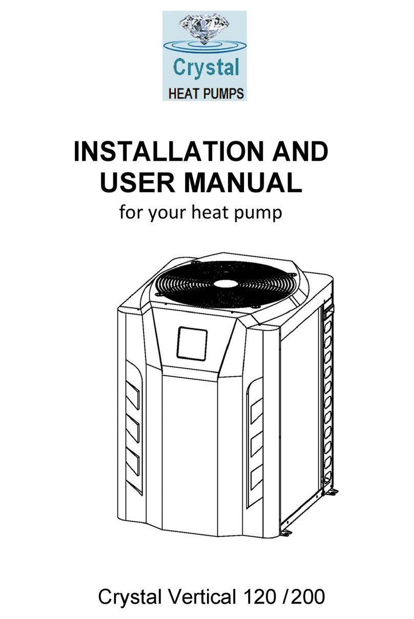
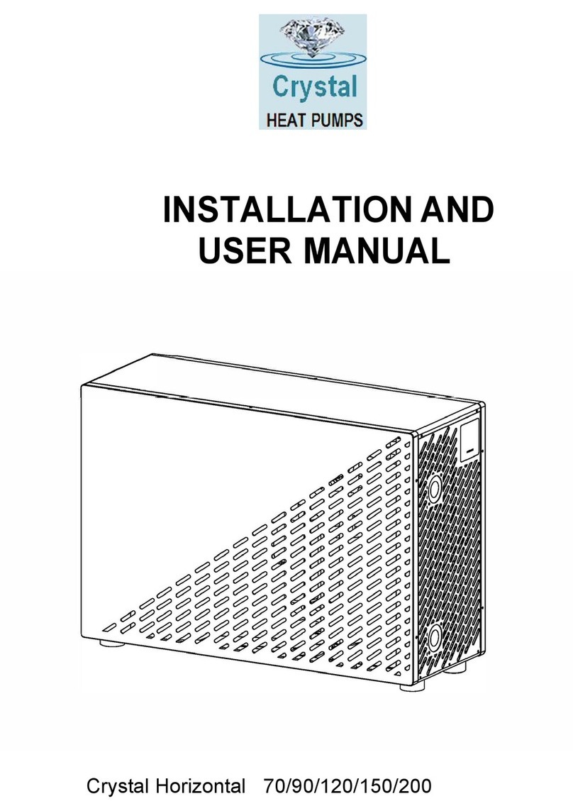
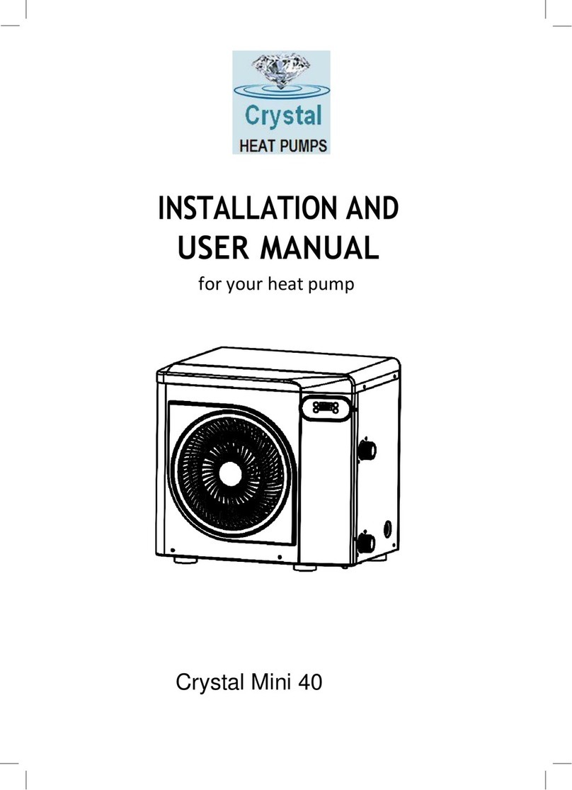
Crystal CHP075PX User manual


Please read and understand ALL the instructions
before installation and use.

-1-
This is for information purposes only as all our PX models are below the 7kgs threshold of R32Gas.
Regulation (EU) n° 517/2014 of 16/04/14 on fluorinated greenhouse gases and
repealing Regulation (EC) n° 842/2006
Leak checks
1. Operators of equipment that contains fluorinated greenhouses gases in quantities of 5 tons of CO2, equivalent or more and not
contained in foams shall ensure that the equipment is checked for leaks.
2. For equipment that contains fluorinated greenhouse gases in quantities of 5 tons of CO2equivalent or more, but of less than 50
tons of CO2equivalent: at least every 12 months.
Picture of the equivalence CO2
1. Load in kg and Tons amounting CO2.
Load and Tons amounting CO2
Frequency of test
From 7
to
75 kg load = from 5 at 50 Tons
Each year
Do not release R32 coolant liquid into the atmosphere. This is a fluoride greenhouse effect gas covered by the
Kyoto agreement with a global warming potential (GWP) = 675 - (see the European Community regulations on
fluoride greenhouse effect gases Regulation (EU) No 517/2014).
Concerning the Gas R32, 7.40kg amounting at 5 tons of CO2, commitment to check each year.
Training and certification
1. The operator of the relevant application shall ensure that the relevant personnel have obtained the necessary certification, which
implies appropriate knowledge of the applicable regulations and standards as well as the necessary competence in emission
prevention and recovery of fluorinated greenhouse gases and handling safety the relevant type and size of equipment.
Record keeping
1. Operators of equipment which is required to be checked for leaks, shall establish and maintain records for each piece of such
equipment specifying the following information:
a) The quantity and type of fluorinated greenhouse gases installed;
b) The quantities of fluorinated greenhouse gases added during installation, maintenance or servicing or due to leakage;
c) Whether the quantities of installed fluorinated greenhouse gases have been recycled or reclaimed, including the name and
address of the recycling or reclamation facility and, where applicable, the certificate number;
d) The quantity of fluorinated greenhouse gases recovered
e) The identity of the undertaking which installed, serviced, maintained and where applicable repaired or decommissioned the
equipment, including, where applicable, the number of its certificate;
f) The dates and results of the checks carried out;
g) If the equipment was decommissioned, the measures taken to recover and dispose of the fluorinated greenhouse gases.
2. The operator shall keep the records for at least five years, undertakes to carry out the activities for operators and shall
keep records for at least five years.
*Please note*:

-2-
12. WIFI function
ATTENTION: This manual includes all the necessary information the use and
installation of your heat pump .
1.
The installer must read the manual and attentively follow the instructions for
implementation and maintenance.
2.The installer is responsible for the installation of the product and should follow all the
instructions ANY errors due to an installation that does not follow the manual guidelines
will VOID the Warranty.
Any use that does not conform to its manufacturing purpose will be regarded as dangerous
and will VOID any Warranties.
for
Thank you for choosing our CHP-PX range for your swimming pool heat pump for your pool heating
needs, it will heat your water and keep the temperature constant when ambient temperatures are at
-20℃to 43℃. As long as the H/P unit purchased has been sized correctly to your specific
requirements, with adequate pool & plumbing, insulation and an insulated cover is used. Please
call supplier to discuss.
INDEX:
1. Specification
2. Dimension
3. Stock advice
4. Installation
5. Adjust the by-pass kit
6. Initial operation
7. Controller Operation
8. Electrical Wiring
9. Malfunction and Trouble shooting
10. Exploded view
11. Maintenance
WARNING :
Please always keep heat pump in well ventilated place and away from anything which could cause fire.
Do not braze or weld the pipe if there is refrigerant inside machine. Please do not charge the gas when in
a confined space.
Please always empty the water in the heat pump during winter time if not in use or when the ambient
temperature drops below 3℃, the Titanium Exchanger will be damaged by being frozen, in such cases,
your warranty will be VOID.
Please always turn off & isolate the power supply if you want to open the cabinet to reach inside the heat
pump.
Please keep the display controller in a dry area to protect the display controller from being damaged by
humidity, such damage will VOID the Warranty for the display.
The action of filling gas must be conducted by a professional with an R32 operating license.

-3-
1. Specification
Model
CHP075PX
CHP095PX
CHP115PX
CHP135PX
CHP165PX
CHP205PX
CHP255PX
CHP305PX
* Performance at Air 28℃, Water 28℃, Humidity 80%
Heating capacity
kW
7.5-2.3
9.5-2.4
11.5-2.9
13.5-3.2
17.1-3.7
20-4.6
25.5-5.9
30-6.7
Power
consumption
kW
1.19-0.15
1.51-0.15
1.83-0.18
2.14-0.2
2.76-0.23
3.28-0.29
4.18-0.37
4.91-0.42
C.O.P.
16-6.3
16-6.3
16-6.3
16-6.3
16-6.2
16-6.1
16-6.1
16-6.1
* Performance at Air 15℃, Water 26℃, Humidity 70%
Heating capacity
kW
5-2.1
6.8-2.2
8.2-2.3
10.1-2.4
12-3.2
15-3.9
19-4.8
23.5-5.5
Power
consumption
kW
1.11-0.26
1.45-0.28
1.74-0.29
2.15-0.3
2.55-0.4
3.19-0.49
4.04-0.6
5.0-0.69
C.O.P.
8-4.5
8-4.7
8-4.7
8-4.7
8-4.7
8-4.7
8-4.7
8-4.7
Voltage
V
220V-240V/50Hz or 60Hz/1PH
Rated current
A
5.0
6.7
8.2
9.5
11.5
14.9
18.6
22.3
Min. MCB fuse
A
16
16
16
25
25
30
30
40
Main cable
mm2
1.5
2.5
2.5
2.5
4
4
4
6
Advised pool volume
(with pool cover)
m³
11-26
12-34
14-62
16-65
24-86
54-118
63-132
70-182
Advised waterflux
m3/
h
2.6
2.9
3.8
4.2
4.7
5.2
8.2
10.3
Water pressure drop
Kpa
12
12
14
15
15
18
18
18
Water connection
mm
48.3/50
No. of Fan
1
2
Noise level(10m)
dB(
A
)
≤ 25
≤ 25
≤ 27
≤ 28
≤ 30
≤ 32
≤ 32
≤ 33
Noise level(1m)
dB
(A
)
32-45
32-46
33-46
34-48
34-48
35-50
35-50
36-52
* Dimension/ Weight
Net weight
kg
56
68
73
78
98
117
128
130
Gross weight
kg
68
73
78
83
113
135
146
148
Net dimension
mm
855*325*565
986*352*672
1040*355*895
1040*355*
1295
Packing
dimension
mm
925*417*616
1051*435*717
1140*480*917
1105*470*
1322
* Above data may be modified without notice.

-4-
2. Dimension (unit: mm)
2.1 Model: CHP075PX, CHP095PX

-5-
2.2 Model: CHP115PX, CHP135PX, CHP165PX.
2.3 Model: CHP205PX, CHP255PX

-6-
2.4 Model: CHP305PX.

-7-
3. Stock advice for R32 models
The warehouse should be bright, spacious, open, well ventilated, have ventilation
equipment and no fire source.
*VERY IMPORTANT* Heat pumps must be stored and transferred in a vertical position in its
original packaging. If this is not the case, the heat pump cannot be operated until a
minimum period of 24hrs has passed with the unit upright, before the unit can have the
electrical power turned on.
Smoking and the use of flames are prohibited near R32machine.
Water connections are not to be used as load bearing handles. The manufacturer does not accept
"ANY" responsibility for "ANY" damage to the water pipes.
4. Installation
4.1 Accessories list
Anti-vibration base, 4 pcs
Draining plug, 2 pcs
Water drainage pipes, 2 pcs
Winter Cover, 1 pc
Water connection assembly, 4 sets (2 sets 48.3mm, 2 sets 50mm )

-8-
4.2 Accessories Installation
Anti-vibration bases
1. Take out 4 Anti-vibration
bases
2. Install them on the bottom of
machine.
Note: Lift the heat pump to install the draining plug. Never
overturn the heat pump, it could damage the compressor.
Draining plug (NOT winter use
see further info regarding winter
use)
1. Install the draining plug under
the bottom panel
2. Connect with a water pipe to
drain out the water.
Water Inlet & outlet junction
1.Use the pipe tape to connect
the water Inlet & outlet junction
onto the heat pump.
2.Install the two joints like the
picture shows.
3. Screw them onto the water
Inlet & outlet junction.
NOTE: Please check for any shipping moved/damaged pipe work
etc. that is too close to other items that may cause vibration and
rubbing as this would be classed as shipping damage and "NOT"
a warranty issue.
Mains Cable wiring
1. Open the top cover of the
heat pump.
2.Connect the cables in the
correct terminal according to
electric diagram.
3. Please take note of length of
cable runs and possibly
upgraded cable requirement.
NOTE: Any damage caused or PCB`s damaged by doing this
will VOID the warranty.
Filtration pump wiring (Dry
contact)
1. Open the top cover of the
heat pump.
2. Connect the cables in the
correct terminal according to
electric diagram.

-9-
Dry contact timer connection
Timer
Dry contact pump connection
Water pump

-10
-
4.3 Installation of heat pump
(1) The heat pump must be installed by professional technicians, otherwise it may be damaged or
even broken.
(2) The unit is designed for outdoor location with good ventilation. Recirculation of cold discharge air
back into evaporator coil will greatly reduce heating capacity and efficiency of the unit, which will
void the compressor warranty.
(3) The unit can be installed almost anywhere in the outdoors. To get a good performance ,it needs
to meet the three factors :
a) Good ventilation
b) Stable and reliable power supply
c) Recycled water system
The difference from a gas water heater is, it should not bring environmental pollution or have
any installation problems in-windy areas.
(4) The unit should not be installed in a limited air ventilation area or placed in or near vegetation
that will block the air inlet.
These locations would deny the unit a continuous source of fresh air. When seasons change,
leaves maybe sucked onto the evaporator coil, thereby reducing its efficiency and impact on its
service life.
(5) For indoor installation, please request more instructions from your supplier and technicians.
(6) When a bypass is installed, flow should not exceed 30% of the nominal flow rate.
(7) Installer must make the water level higher than the circulation pump location. Unless a One-Way
Check Valve is used in the plumbing circuit.
(8) Typically, the pool heat pump unit should be installed aside a pool, less than 7.5 meters distance. But,
at least 2m away from the pool so a person cannot touch the pool and the heat pump at the same time,
as this would lead to electrical safety concerns.
(9) To get the best from the heat exchanger of the heat pump unit, it should be matched with the
nominal flow rate of water flow recommended in the specification sheet.
(10) We consider it good practice to place a discharge pipe in the lowest pipe to prevent freezing in
cold season. Put "T" fitting and ball valve to facilitate discharging the water in winter or emptying the
water out of the system to prevent freezing when the HP stops operating at the ambient
temperature below 3c, otherwise the unit may be damaged.
(11) It is suggested to install the quick adapter in front of the water in-out connection, which could
discharge water easily to prevent water freezing. This would be convenient for maintenance and
servicing.
(12) When the unit is running, there will be some condensation water discharged from the bottom.
For Summer Spring and Autumn use, please hold the drainage nozzle (accessory) into the hole
and clip well, then connect a pipe to drain the condensation water out. This tube and drain "IF"
used must be checked for blockages regularly as leaves and debris will block this.

-11 -
(13) The below picture shows the minimum required distances on each side of the heat pump.
*Absolute Minimum Clearance dimensions*
(14) If water pressure is over 10 KPA, or water flow rate is more than 11 cubic meters through
heat exchanger, it is necessary to install the by-pass pipe in water system.
(15) Installation illustration
NOTE: The factory only provides the heat pump unit. The other items in the illustration are
necessary spare parts for the water system which are provided by users or installers.
ATTENTION:
Please follow these steps when operating for the first time :
1. Open the diversion heat pump valves to charge H/P with water and close the
by-pass valve (direct line)
2. Make sure that the pump and the water-in pipe have been filled with water.
Make sure there are no Air-Locks.
3. Start the unit

-12 -
(16) The location of a chemical introducer into your system is also critical to the heater’s life.
If an automatic chlorinator or brominator is used, it must be located downstream of the heater.
A "ONE" way check valve must be installed between the chlorinator and the heater to prevent
chlorine returning into the heat pump. (See below pictures)

-13 -
5. Adjusting the bypass
Use the following procedure to adjust the bypass:
1.Valve 1 wide open. Valve 2 & valve 3 closed.
2.
Slowly open valve 2 & valve 3 by half, then close the valve 1 slowly to increase the water flow to valve 2
& valve 3.
3.
If it shows‘ON` or `EE3’ on the display, it means the water flow into the heat pump is not enough, then
you need to adjust the valves to increase the water flow through the heat pump.
How to get the optimum water flow:
Please turn on the heat pump under heating function, firstly close the by-pass then open it slowly to start the
heat pump (the machine can't start running when the water flow is insufficient).
Continue to adjust the by-pass slowly, at this time check the Inlet water temp. & Outlet water temp., it will be
optimum when the difference is around 2 degree.
Drain out the water in winter for the units without drainage outlet in heat exchanger
Turn off the heat pump and be sure that it is disconnected from
power Turn off the water pump

-14 -
-Close the valves 1 and 2
-Open the valve 4
Allow water to drain out over a long period until the heat pump is fully drained.
NOTE: Close the valve 4 before turn on the heat pump.
6. Initial operation
Note: In order to heat the water in the pool (pond or hot tub), the filter pump must be running
to cause the water to circulate through the heat pump. The heat pump will not start up if the
water is not circulating.
After all connections have been made and checked, carry out the following procedure:
1) Switch on the filter pump. Check for leaks and verify that adequate water is flowing from and to
the swimming pool.
2) Connect power to the heat pump and press the On/Off button on the electronic control panel.
The unit will start up after the time delay expires (see below).
3) After a few minutes, check whether the air blowing out of the unit is cooler.
4) When the filter pump is turned off, the unit should also turn off automatically, if not, then adjust
the flow switch.
5) Allow the heat pump and the filter pump to run 24 hours a day until the desired water
temperature is reached. The heat pump will stop running at this point. After this, it will restart
automatically (as long as the filter pump is running) whenever the swimming pool water
temperature drops 2 degree below the set temperature.
Depending on the initial temperature of the water in the swimming pool and the air temperature, it
may take several days to heat the water to the desired temperature. A good swimming pool cover
can dramatically reduce the required length of time.
Water Flow Switch:
Your heat pump is equipped with a flow switch for protecting the HP unit running with adequate
water flow rate. The heat pump will turn on when the pool pump runs and shut the heat
pump off when the pool pump shuts off. If the pool water level is higher than 1m above or below
the heat pump’s automatic adjustment knob, your dealer may need to adjust its initial start up.
Time delay - The heat pump has a built-in 3-minute start-up delay to protect the circuitry and avoid
excessive contact wear. The unit will restart automatically after this time delay expires. Even a brief
power interruption will trigger this time delay and prevent the unit from restarting immediately.
Additional power interruptions during this delay period do not affect the 3-minute duration of the
delay.
Condensation
The air drawn into the heat pump is strongly cooled by the operation of the heat pump for heating
the pool water, which may cause condensation on the fins of the evaporator. The amount of
condensation may be as much as several litres per hour at high relative humidity. This is
sometimes mistakenly, regarded as a water leak.

-15 -
Pressure gauge display (R32)
Examine the pressure gauge which indicates the refrigerant gas pressure of the unit, the below
table shows the normal value of the gas pressure (R32) when the machine is in power off or running
conditions.
Unit Condition
Power Off
Ambient (℃)
-5~5
5~15
15~25
25~35
Water temp (℃)
/
/
/
/
Pressure gauge (Mpa)
0.59~0.85
0.85~1.18
1.18~1.59
1.59~2.1
Unit Condition
Running
Ambient (℃)
/
/
/
/
/
Water temp (℃)
10~15
15~20
20~25
25~30
30~35
Pressure gauge (Mpa)
1.1~1.6
1.3~1.8
1.5~2.1
1.7~2.4
1.9~2.7
7. Controller Operation
7.1 Guide for operation
7.2 The keys and their operations
7.2.1 button
Press to start the heat pump unit.
Press to stop the heat pump unit.
7.2.2 and button
Water temperature setting:

-16 -
Press or to set the water
Press and at the same time to check water in temperature, water out temperature
and set temperature.
7.2.3 button
Press to change the working mode, Powerful, silent and smart. The default mode is smart
mode.
7.2.4 button
Press for 2 seconds to enter secondary page.
Press and to select the functions and press to enter.
7.2.5 Heating/Cooling/Auto mode
Select and press to enter, press and to choose Heating/ Cooling/
Auto mode, press again to exit. The default mode is Heating mode.
Logic of auto mode:T1=Water inlet temperature /Tset= set temperature=28c
temperature.

-17 -
Parameter checking
and press to enter, press and to check d0-d11 value. Press
checking.
Code
Condition
Scope
Remark
d00
IPM mould temperature
0-120℃
Real testing value
d01
Inlet water temp.
-9℃~99℃
Real testing value
d02
Outlet water temp.
-9℃~99℃
Real testing value
d03
Ambient temp.
-30℃~70℃
flash if Real value<-9
d04
Frequency limitation code
0,1,2,4,8,16
Real testing value
d05
Piping temp.
-30℃~70℃
flash if Real value<-9
d06
Gas exhaust temperature
0℃~C5℃(125℃)
Real testing value
d07
Step of EEV
0~99
N*5
d08
Compressor running
frequency
0~99Hz
Real testing value
d09
Compressor current
0~30A
Real testing value
d10
Current fan speed
0-1200 (rpm)
Real testing value
d11
Error code for last time
All error code
Remark:
d4: Frequency limitation code,
0: No frequency limit;
1: Coil pipe temperature limit;
2: Overheating or overcooling frequency limit;
4: Drive Current frequency limit;
8: Drive voltage frequency limit;
16: Drive high temperature frequency limit
7.2.6
Select
to exit

-18 -
7.2.7 Parameter setting
Select and press to enter, press and to choose P0-P18 value and
press to set.
Note: Long press for 10s to set P8, P12, P13, P14, P15, P17, P18.
Code
Name
Scope
Defa
ult
Remark
P00
Mandatory defrosting
0-1
0
0: Default normal operation
1: Mandatory defrosting.
P03
Water pump
0-1
0
1:Always running;
0:Depends on the running of compressor
P07
Water temp. calibration
-9~9
0
Default setting: 0
P08
Adjustable for P9-P11
0~1
0
1: Adjustable for P9, P10, P11
0: Not adjustable for P9, P10, P11
P09
Compressor Frequency
18~110
50
Adjustable if P08=1
P10
Opening degree of EEV
0~470
350
Adjustable if P08=1
P11
Fan motor rotate speed
300~1000
500
Adjustable if P08=1
P12
Communication port of
modbus
0~5
0
Only available for HP with modbus
P13
ID NO. of modbus
protocol
1~88
9
Only available for HP with modbus
P14
Restore to factory
settings
0~1
0
0: Default
1: Restore to factory settings
(restore P00, P03, P07, P08, P09, P10, P11
to factory setting)
P15
Model code in modbus
Only available for HP with modbus
P16
Product code
/
/
Depend on the machine
P17
Modules selection
0~1
0
Only available for HP with modbus or wifi
1: Modbus module
0: Wifi module
P18
Mode
0~1
0
1: Heating only
0: Heating/Cooling/Auto mode
This manual suits for next models
7
Table of contents
Other Crystal Heat Pump manuals
Popular Heat Pump manuals by other brands
York
York YAZS022 installation manual

Heat Controller
Heat Controller VMH 09 Replacement parts

Bosch
Bosch BOVA Series installation instructions
STIEBEL ELTRON
STIEBEL ELTRON WPL 15 AS Operation and installation
Oasis
Oasis RAPID PRO RP14 Installation & user manual

EAS Electric
EAS Electric ETH220VMA instruction manual
Carrier
Carrier Puron IP24 owner's manual
Bryant
Bryant Legacy 547K 14 installation instructions
Grant
Grant Aerona3 HPID12R32 Installation and servicing instructions

Mitsubishi Electric
Mitsubishi Electric CITY MULTI PQHY- P216TSLMU-A1 quick start guide
Firefly
Firefly YASBP-56HL User manual, installation & operation

Hotjet
Hotjet MINI 5Ai installation manual
