Sensa-Heat ES Series User manual

ES Series
INVERTER POOL& SPA HEAT PUMP
USER MANUAL

Table of contents
1.Introduction 1
2.Safety precautions 2
2.1 Warning 2
2.2 Attention 3
2.3 Safety 3
3.About your heat pump 4
3.1 Transportation 4
3.2 Accessories 4
3.3 Features 5
3.4 Operating condition and range 5
3.5 Introduction of different modes 5
3.6 Technical parameter 6
3.7 Dimension 7
4.Installation guidance 8
4.1 Installation reminder 8
4.2 Wiring 10
4.3 Electric wiring diagram 10
4.4 Reference for protecting devices and cable specification. 10
5. Operation guidance 11
5.1 Key function Error! Bookmark not defined.
5.2 Temperature display Error! Bookmark not defined.
5.3 Operation instruction Error! Bookmark not defined.
6.Testing 14
6.1 Inspect heat pump before use. 14
6.2 Refrigerant leakage detection method 14
6.3 Trial 14
7.Maintenance 15
8.Trouble shooting for common faults. 16
9.Water pump connection 18
10.Wi-Fi operation 23
11.Warranty 29
.

1
1.Introduction
Congratulations on the purchase of your new ES Series Heat Pump.
The ES Series Heat Pump has been specifically designed for Pool & Spa applications ensuring optimum
performance and many years of trouble-free operation.
Please read and understand this complete user manual before attempting to install your ES Series Heat
Pump,
Thank you!
Model Number_____________________________________
Serial Number_____________________________________
Date of Purchase___________________________________
Invoice Number____________________________________
Please record the information above during installation, as this will be
required for any service/warranty work that may be required.
The Sensa-Heat range of products are proudly designed and distributed by:
Spa-Craft Pty Ltd
1300 498 819
20 Curtis Rd Mulgrave
NSW 2756 Australia
2
2.Safety precautions
We have provided important safety messages in this manual for the installation and upkeep of your heat
pump.
Please thoroughly read and obey all safety messages in this manual.
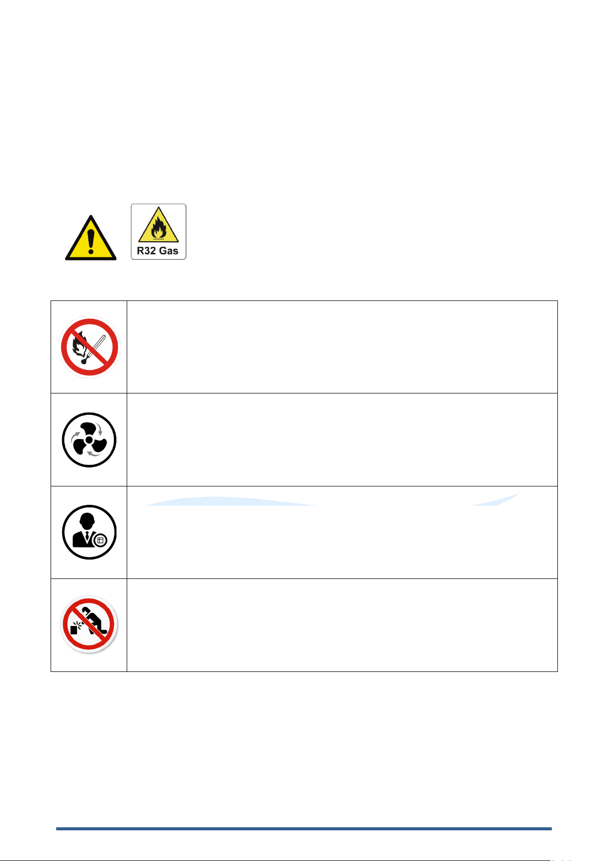
Environment friendly R32 Refrigerant is used for this heat pump.
2.1 Warning
This WARNING signed notes a hazard. It calls attention to a procedure,
practice, or the like, which, if not correctly performed or adhered to, could
result in personal injury or injury to a third party. These signs are rare but
are extremely important.
a. Keep the heat pump away from fire source.
b. The Heat Pump must be placed in a well-ventilated area, indoor or enclosed areas
are not allowed.
c. Repair and disposal must be carried out by trained service personnel.
d. Vacuum the system before welding. Welding can only be carried out by aqualified
service technician.

3
2.2 Attention
a. Please read the following instructions before installation, use and maintenance.
b. Installation must be carried out by a competent person in accordance with this manual.
c. Check all plumbing before operating the heat pump, insure there are no water leaks.
d. Do not obstruct or block air flow near inlet or outlet areas of the heat pump, obstruction to the air flow
will greatly affect the efficiency or damage your heat pump.
e. Carefully set the water temperature on your heat pump to your preference to avoid overheating or
overcooling of your Pool/Spa water
f. To optimize the heating effect, please install heat preservation insulation on pipes between pool/spa
and the heat pump, and please use a recommended cover on your pool or spa.
g. Connecting pipes of the pool/spa and the heat pump should be less than 10m.
h. Except for the methods recommended by the manufacturer, do not use any methods to accelerate
the defrosting process or clean the frosted parts.
i. If a repair is required, please contact the nearest after-sales service center. The repair process must
be strictly carried out in accordance with this manual by an authorized repairer. Unauthorized repairs
will void your warranty.
j. Do not use or stock combustible gas or liquid such as thinners, paint, and fuel near your heat pump
as to avoid a fire risk.
2.3 Safety
a. Please keep the main power supply out of reach from children.
b. When a power cut happens during operating, take caution as the heat pump will automatically
restart once power is reestablished.
c. Please switch off the main power supply in stormy weather to prevent damage that may be caused
by lightning strike.
d. Safety inspection must be carried before the maintenance or repair for heat pumps with R32 gas
to minimize the risk.
e. Any repairs should be conducted in a well-ventilated area. Any ignition source is prohibited during
the inspection.
f. If R32 gas leaks during the installation process, all operations must be stopped immediately and call
an authorized service center.

4
3.About your heat pump
3.1 Transportation
a. Always keep upright.
b. Do not lift the heat pump by the
water unions as this may cause internal damage to
the titanium heat exchanger inside
the heat pumps.
3.2 Accessories
Connection of the condensate drainage kit:

5
3.3 Features
a. Stable DC inverter compressor.
b. EEV Technology.
c. Quick reverse cycle defrosting with 4-way valve.
d. High efficiency twisted titanium heat exchanger.
e. High pressure and low-pressure protection.
f. Soft start & wide voltage application.
g. Stable inverter control system.
3.4 Operating condition and range
a. Air temperature operating range 0°C~43°C
b. Heating temperatures setting range 18°C~40°C.
c. Cooling temperature setting range 12°C~30°C
d.The ideal ambient air temperature for best performance is between air 15°C ~ 25°C.
3.5 Introduction of different modes
a. The heat pump has two modes: Boost and Silence.
b. They have different strengths under different conditions.
Mode
Modes
Strength
Boost mode
Heating capacity: 20% to 100% capacity
Intelligent optimization
Fast heating
Silence mode
Heating capacity: 20% to 80% capacity
Sound level: 3dB(A) lower than Boost mode

6
3.6 Technical parameter
Model
HPES07
HPES09
HPES13
HPES16
HPES20
HPES24
PERFORMANCE CONDITION: Air 27°C/ Water 27°C/ Humid. 80%
Heating capacity (kW)
7.0
9.0
13.0
16.0
20.2
24.2
COP Range
6~10.1
6.2~10.5
6.3~10.8
6.2~10.7
6.2~10.8
6.3~10.8
PERFORMANCE CONDITION: Air 15°C/ Water 26°C/ Humid. 70%
Heating capacity (kW)
5.0
6.5
9.0
11.0
14.0
16.0
COP Range
4.3~6.3
4.2~6.5
4.5~6.2
4.3~6.6
4.2~6.5
4.5~6.6
TECHNICAL SPECIFICATIONS
Advised pool volume(m3) *
15~30
20~45
35~65
40~75
50~90
60~110
Operating air temperature
(℃)
0℃~43℃
Power supply
230V 1Ph
Rated input current(A)
1.00~5.06
1.21~6.7
3
1.76~8.70
2.17~11.12
2.61~14.16
3.13~16.56
Sound level at 10m dB(A)
19.8~31.2
21.6~33.
5
23.9~34
26.2~37.3
26.3~38.1
26.9~38.7
Advised water flux(m³/h)
2~4
3~5
4~6
6~8
7~10
10~12
Water connection (mm)
40
Remarks:
This heat pump can perform normally within an air temperature of0℃~+43℃, efficiency will not be
guaranteed out of this range. Please take into consideration that the pool heat pump performance and
parameters are different under various conditions.
Related parameters are subject to adjustment periodically for technical improvement without further
notice. Please refer to the ID plate on your heat pump for up-to-date details.
7
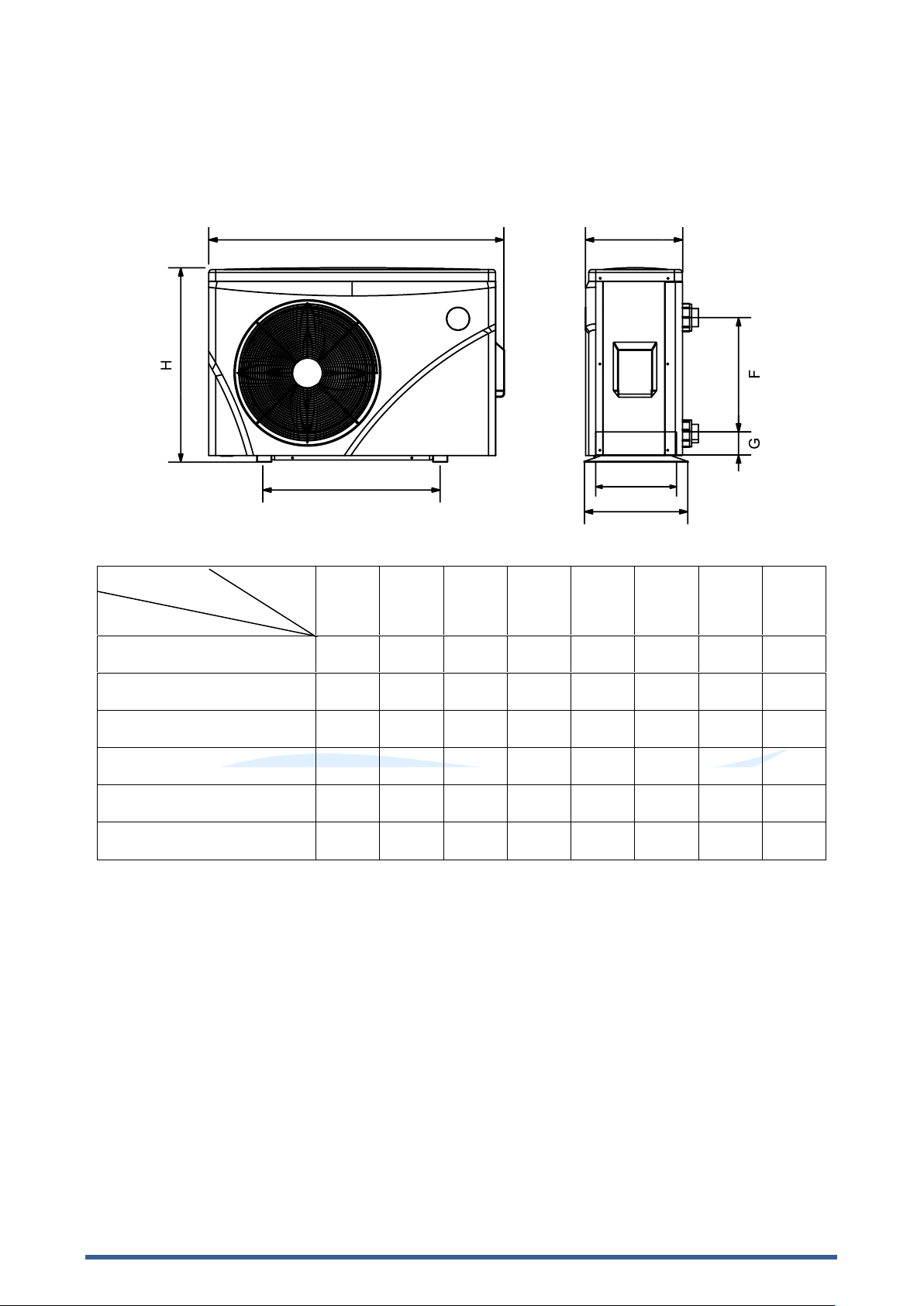
3.7 Dimension
※Above data is subject to modification without notice.
Note:The picture above is the specification diagram of the pool& spaheat pump
installation and layout reference only. The product is subject to adjustment periodically for improvement
without further notice.
A
B
C
D
E
F
G
H
HPES07
334
490
341
359
744
310
74
648
HPES09
324
560
347
349
903
250
74
654
HPES13
324
560
347
349
903
320
74
654
HPES16
324
590
347
349
991
350
74
654
HPES20
324
590
347
349
991
350
74
754
HPES24
395
590
415
420
990
460
74
757
Name
Size (mm)
Model

8
4.Installation guidance
4.1 Installation reminder
Only competent persons are authorized to install the heat pump and should be educated with the
relevant building codes and standards of their state or local governing body. All electrical connections
must be performed by a licensed electrician.
a. Location and clearances see appendix for further ventilation scenarios.
b. The heat pump should be installed in an outdoor location with adequate ventilation. Installing a
heat pump without adequate ventilation will result in poor performance or damage to your heat
pump.
c. The heat pump must be installed in an easily accessible position to ensure easy access when
maintenance and service is required.
The inverter heat pump should be installed in an outdoor well ventilation area. The below diagram
displays the minimum ventilation area, for optimum performance it is advised to exceed the minimum
clearances.

9
d. Typical plumbing installation diagram,
NOTE: If installing the heat pump on an existing pump/filtration setup, the heat pump
must be installed after the pump/filter and before the chlorinator/sanitizer
Please note:Water connection locations may differ from the diagram; this diagram is to be used
as a guide only!
1) The frame must be fixed by bolts (M10) to concrete foundation or brackets. The concrete
foundation must be solid and fastened; the bracket must be strong enough and antirust treated;
2) Do not stack substances that will block air flow near inlet or outlet area, and there is no barrier
within 50cm behind the main heat pump, or the efficiency of the heat pump will be reduced or
maydamage your heat pump
3) The heat pump needs an appended water pump (Supplied by the user). The recommended
pump must meet required flow rates as per the
4) When the heat pump is running, there will be condensation water discharged from the bottom of
the heat pump. Please insure the drainage nozzle (included with your heat Pump) is inserted
into the dranige hole and clip in, connect a pipe to drain the condensation water out.
e. The inlet and outlet water unions cannot stand the weight of flexible pipes. The heat pump must
be plumbed with rigid pipes!

10
4.2 Wiring
a. Connect to appropriate power supply, the voltage should comply with the rated voltage of the
products.
b. Heat pump must be earthed.
c. Wiring must be handled by a professional technician according to the circuit diagram.
d.
e. The layout of power cable and signal cable should be orderly and not affecting each other.
4.3 Electric wiring diagram
For power supply: 230V 50Hz
4.4 Reference for protecting devices and cable specification.
※Above data is subject to modification without notice.
Note: The above data is based on power cables less than10m long. If the power cable required ismore
than 10m, wire diameter must be increased in accordance with local power regulations. The signal
cable can be extended to 50mmaximally.
MODEL
HPES07
HPES09
HPES13
HPES16
HPES20
HPES24
Breaker
Rated Current (A)
8
9.5
15
20.5
23.5
25
Rated Residual Action Current
(mA)
30
30
30
30
30
30
Power Supply
230V 50Hz
Earthing
Distribution Box (Not Supplied)
Power Cord
Swimming Pool Heat Pump Wiring Board
Fuse
Breaker
11
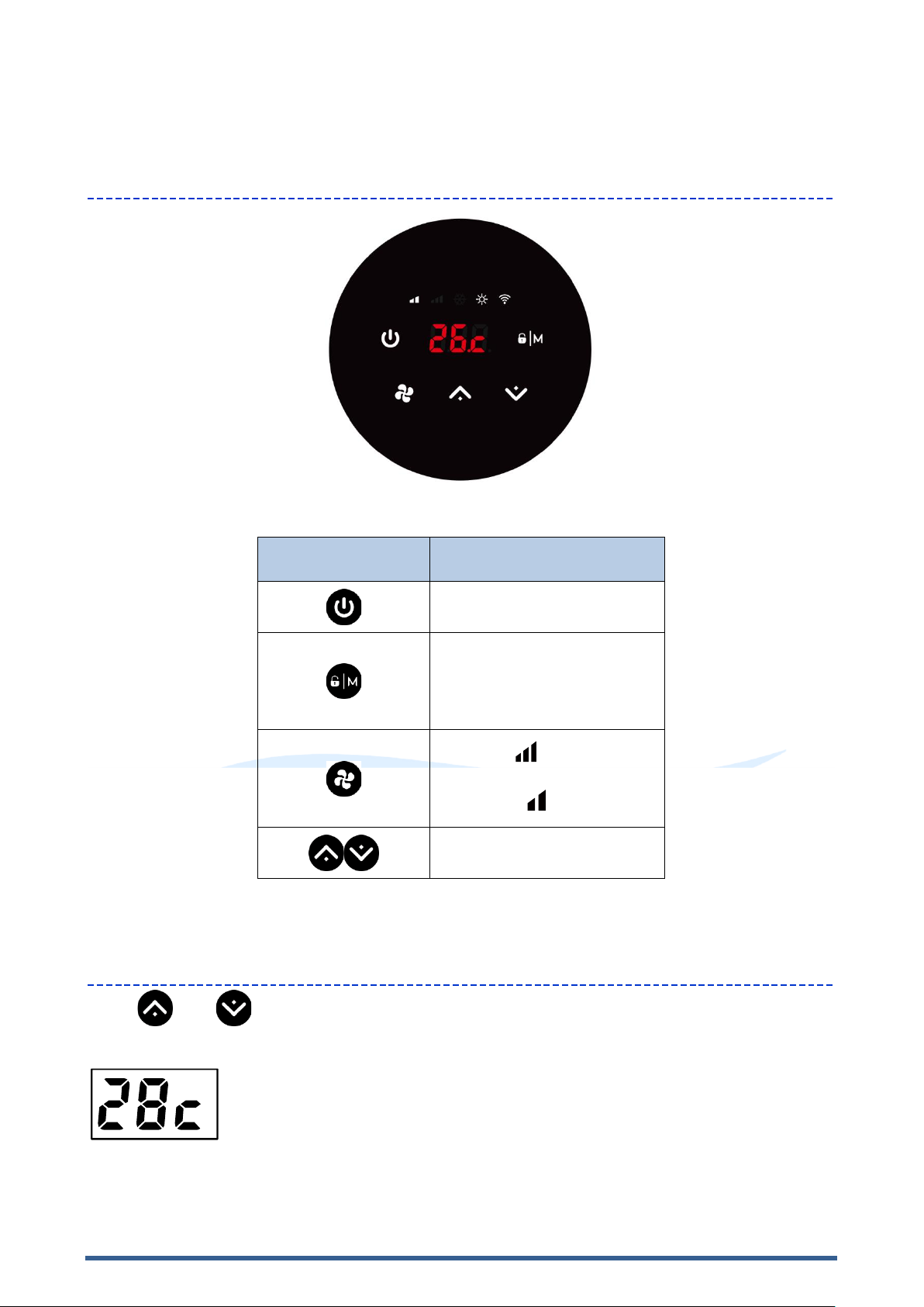
5. Operation guidance
1. Key function
Symbol
Heating & cooling models
1. Power On/Off
2. Wi-Fi setting
1. Lock/Unlock Screen
2. Heating mode (18-40°C)
3. Cooling mode (12-30°C)
4. Auto mode (12-40°C)
1. Boost
2. Silence
Temperature Setting
2. Temperature display
Press and together for 5 second to switch temperature display.
a. Celsius display:
means 28℃
b. Fahrenheit display (only the temperature number):

12
means 104℉
3. Operation instruction
a. Screen Lock
1)
2) Automatic Lock Period: 30 seconds if no operation
b. Power On
.
c. Temperature Setting
When the machine is on, press and to set temperature.
d. Boost/Silence Mode
Press , silence mode
Please choose boost mode for initial heating
e. Heating / Cooling /Auto Mode(heating & cooling models only)
cooling
Heating mode Water temperature setting range(18-40°C)
Cooling mode setting range(12~30°C)
Auto mode setting range(12~40°C)
* When water inlet temperature is higher than setting point, automatic cooling mode starts.
* When water inlet temperature is lower than setting point, automatic heating mode starts.
f. Defrosting
1) Automatic defrosting: When machine is auto defrosting, will flash, and return to previous
working mode when it finishes.
2) Manual Defrosting: To enter forced defrosting mode, the compressor must be working more than 10
minutes. in heating mode, press and on touch controller simultaneously for 5
seconds to start forced defrosting, d
defrosting stops.
(Remarks: the interval between forced defrosting should be more than 30 minutes.)
13
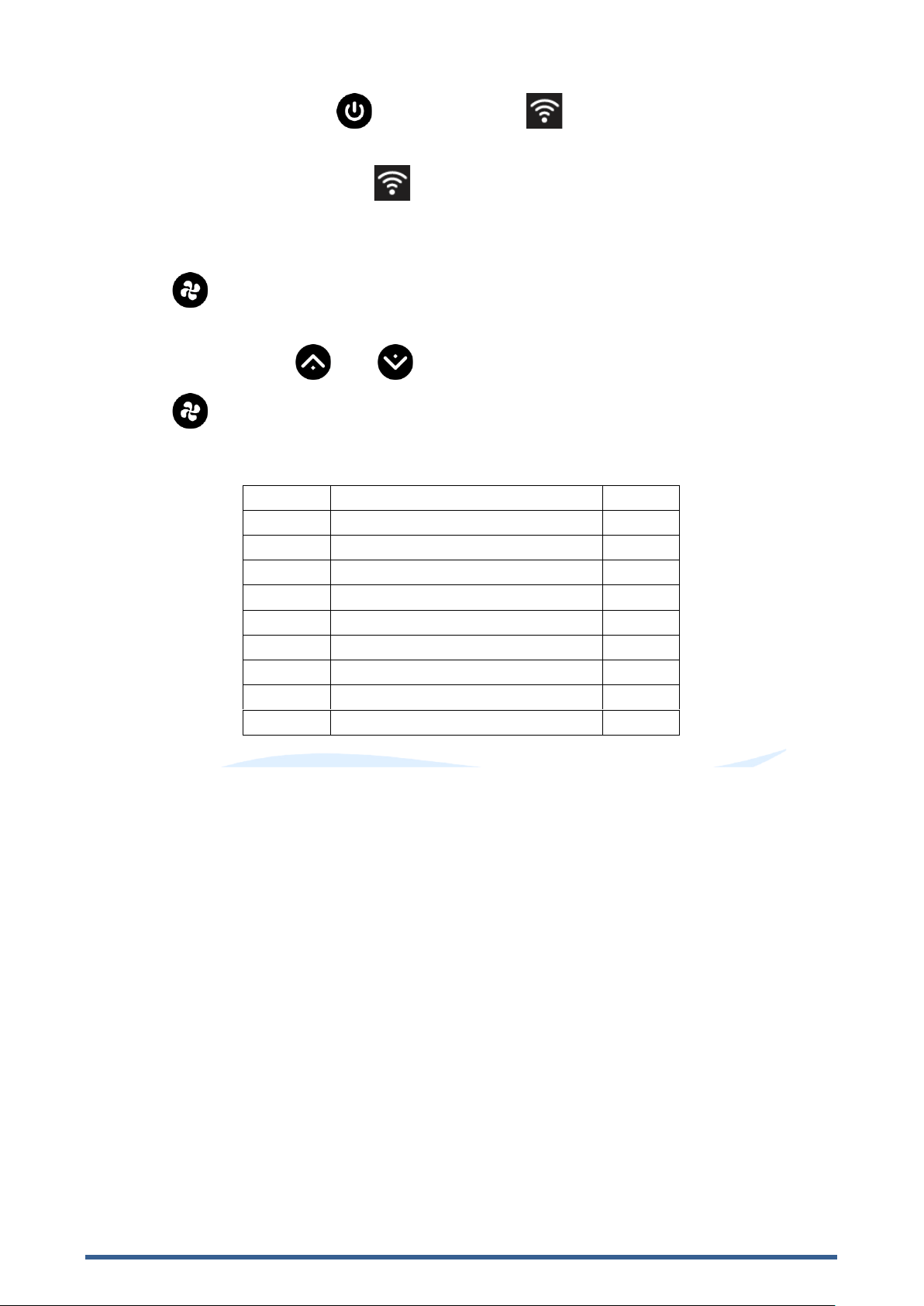
g. Wi-Fi Setting
When the screen is on, press -Fi connection.
Connect Wi-Fi on mobile phone and input password, and then control equipment by Wi-Fi. When
APP connects Wi-Fi successfully, .
h. Running Status Checking
1)
2) and its corresponding value.
3)
4)
5) Running status checking table:
Symbol
Content
Unit
C0
Inlet water temp
°C
C1
Outlet water temp
°C
C2
Ambient temp
°C
C3
Exhaust gas temp
°C
C4
Evaporator coil pipe temp
°C
C5
Return gas temp
°C
C6
Cooling coil pipe temp
°C
C9
Cooling plate temp
°C
C10
EEV opening angle
P

14
6.Testing
6.1 Inspect heat pump before use.
a. Check the heat pump has adequate ventilation,ensure air inlets and outlets, and are not obstructed.
b. Ensure heat pump is not installed in a corrosive environment.
c. Check electric wiring is fasten and wired correctly, ensure unit is fully earthed. (all electrical work
must be carried out by a licensed electrician)
d. Check all plumbing for any water leaks,
6.2 Refrigerant leakage detection method
a. Leakage checking is prohibited in enclosed area.
b. Any ignition source is prohibited during the leakage inspection. A halide torch (or any
other detector using a naked flame) shall not be used.
c. Leakage detection fluids can be applied with most refrigerants but the use of detergents containing
chlorine shall be avoided as the chlorine may react with the refrigerant and corrode the copper pipe.
d. Vacuumize completely before welding. Welding can only be carried out by professional personnel.
e. Please stop using while gas leakage occurs and contact professional personnel in service center.
6.3 Trial
a. The water pump must be started before the heat pump and turned off before the heat pump to avoid
any damage to the heat pump.
b. Before starting the heat pump, please check for any water leaks.
c. To protect the heat pump, the heat pump is equipped with a time lag function, the fan will run for 1
minute before the compressor is turn on and for1 minute after the compressor has turned off.
d. After the heat pump starts up, please check for any abnormal noises from the heat pump.
NOTE: For optimum efficiency, the water inlet to outlet temperature differential should be
between 2-3 degrees
The running status function on the touch pad will verify inlet and outlet temperatures, adjust
water by pass vales to active optimum water flow rates.

15
7.Maintenance
1. In the winter season when the heat pump is not in operation.
a. Cut off power supply to prevent any damage to the heat pump.
b. Drain all the water from the heat pump.
c. Cover the heat pump when not in use.
2. Please clean this heat pump with household detergents or clean water, NEVER use petrol,
thinners,or any similar fuel.
3. Check bolts, cables, and connections regularly.
4. If repair or removal is required, please contact authorized service center nearby.
5. Do not attempt to work on the equipment by yourself. Improper operation may cause danger.
6. To reduce risk, safety inspection must be carried out before the maintenance or repair of heat pumps
with R32 gas.
!!Important:
Unscrew the water nozzle of inlet
pipe to let the water flow out.
When the water in heat pump freezes in
winter season, the titanium heat exchanger
may be damaged.
“SWITCH OFF”power supply to the heat
pump before cleaning, examination and repair
repairing

16
8.Trouble shooting for common faults.
1. Repairing Guidance
-----------------------------------------------------------------------------------------------------------------------------------------
WARNING
a. If repair or removal is required, please contact an authorized service center.
b. Requirements for Service Personnel
c. Any person who is involved with working on or breaking into a refrigerant circuit should hold
a current valid certificate from an industry-accredited assessment authority, which
authorizes their competence to handle refrigerants safely in accordance with an industry
recognized assessment specification.
d. Do not attempt to work on the equipment by yourself. Improper operation may cause danger.
e. Strictly comply with the manufacturer's requirements when charging R32 gas and equipment
maintenance. This chapter focuses on special maintenance requirements for swimming pool
heat pump with R32 gas. Please refer to the technical service manual for detailed
maintenance operation.
f. Vacuumize completely before welding. Welding can only be carried out by professional
personnel in service center.
Failure solution and code
----------------------------------------------------------------------------------------------------------------------------------------
Failure
Reason
Solution
Heat pump does not run
No power
Wait until the power recovers
Power switch is off
Switch on the power
Fuse burned
Check and change the fuse
The breaker is off
Check and turn on the breaker
Fan running but with
insufficient heating
Evaporator blocked
Remove the obstacles
Air outlet blocked
Remove the obstacles
3 minutes start delay
Wait patiently
Display normal, but no heating
Set temp. too low
Set proper heating temp.
3 minutes start delay
Wait patiently
If above solutions do not work, please contact your installer with detailed information and your model
number. Do not try to repair it yourself.
Note: If the following conditions happen, please stop the heat pump immediately, and cut off the
power supply immediately, then contact your dealer:
1. Inaccurate switch action.
2. The fuse is frequently tripping, or leakage circuit breaker tripped.

17
Protection &Failure code
NO.
Display
Protection code description
1
E3
No water protection
2
E5
Power supply excesses operation range (not failure)
3
E6
Excessive temp difference between inlet and outlet water (Insufficient
water flow protection)
4
Eb
Ambient temperature too high or too low protection (not failure)
5
Ed
Anti-freezing reminder (not failure)
NO.
Display
Failure code description
1
E1
High pressure protection
2
E2
Low pressure protection
3
E4
3 phase sequence protection (three phase only)
4
E7
Water outlet temp too high or too low protection
5
E8
High exhaust temp protection
6
EA
Heat exchangers overheat protection/Evaporator overheat protection
(only at cooling mode)
7
P0
Controller communication failure
8
P1
Water inlet temp sensor failure
9
P2
Water outlet temp sensor failure
10
P3
Gas exhaust temp sensor failure
11
P4
Evaporator coil pipe temp sensor failure
12
P5
Gas return temp sensor failure
13
P6
Cooling coil pipe temp sensor failure
14
P7
Ambient temp sensor failure
15
P8
Cooling plate temp. sensor failure
16
P9
Current sensor failure
17
PA
Restart memory failure
18
F1
Compressor driver module failure
19
F2
PFC module failure
20
F3
Compressor start failure
21
F4
Compressor running failure
22
F5
Inverter board over current protection
23
F6
Inverter board overheat protection
24
F7
Current protection
25
F8
Cooling plate overheat protection
26
F9
Fan motor failure
27
Fb
Power filter plate No-power protection
28
FA
PFC module over current protection
18
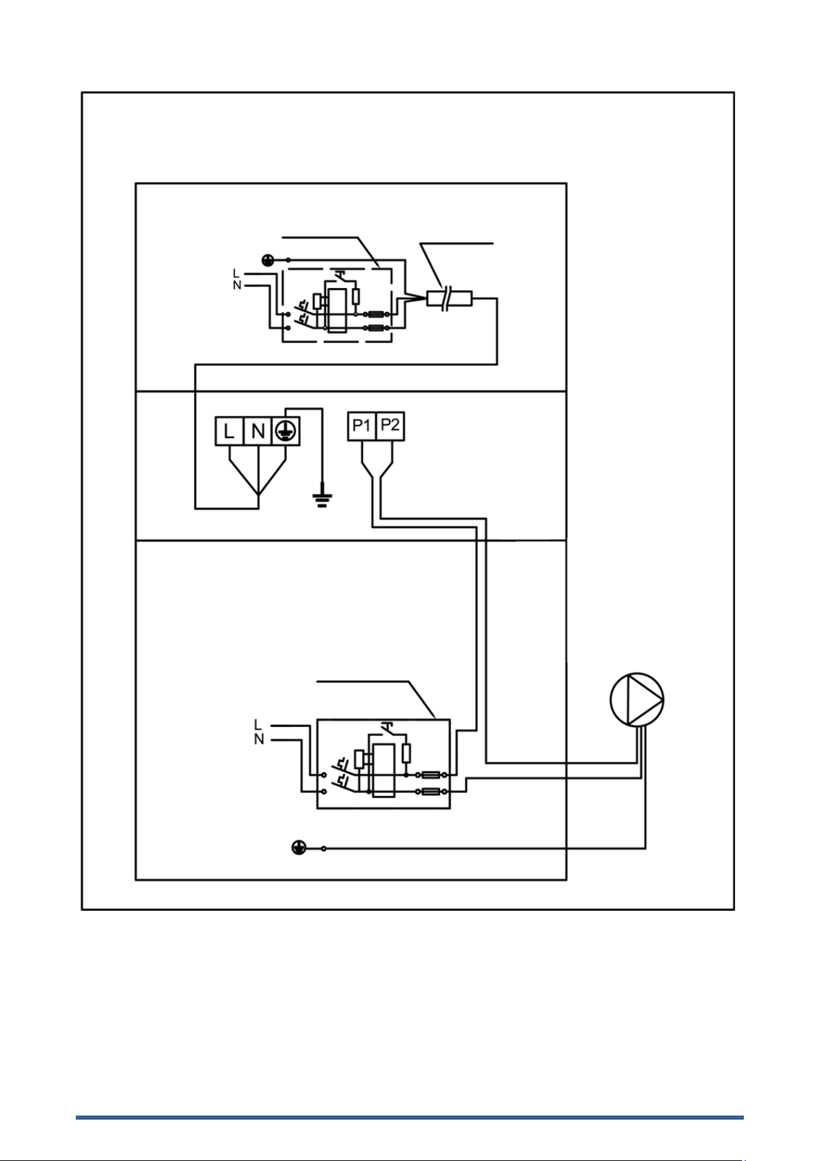
9.Water pump connection
Breaker/fuse
(Customer prepare)
Earthing
Power Supply
230V~/50Hz
Water pump: 230V voltage, ≤500W capacity
Water Pump
Breaker/fuse
(Customer prepare)
Power Supply
230V~/50Hz
Earthing
Power cord
This manual suits for next models
6
Table of contents
Other Sensa-Heat Heat Pump manuals

Popular Heat Pump manuals by other brands

Trane
Trane Axiom GEHB Installation operation & maintenance

Dimplex
Dimplex LI 11TER+ Installation and operation instruction

HTW
HTW RSJ Series Owners and installation manual

SOLARFOCUS
SOLARFOCUS vampair K 08 installation manual

Carrier
Carrier 38BYC Series Installation and start-up instructions

SolarEast
SolarEast BLN-006TB1 manual


