Crystal Vertical 120 User manual

INSTALLATION AND
USER MANUAL
foryourheatpump
Crystal Vertical 120 / 200

1
This heat pump contains a flammable refrigerant R32.
Any intervention on the refrigerant circuit is prohibited without a valid authorization.
Before working on the refrigerant circuit, the following precautions are necessary for safe work.
1.
Work procedure
The work must be carried out according to a controlled procedure, in order to minimize the risk of
presence of flammable gases or vapors during the execution of the works.
2.
General work area
All persons in the area must be informed of the nature of the work in progress. Avoid working in a confined area. The
area around the work area should be divided, secured and special attention should be paid to nearby sources of flame
or heat.
3.
Verification of the presence of refrigerant
The area should be checked with a suitable refrigerant detector before and during work to ensure that there is no
potentially flammable gas. Make sure that the leak detection equipment used is suitable for flammable refrigerants, is it
does not produce sparks, is properly sealed or has internal safety.
4.
Presence of fire extinguisher
If hot work is to be performed on the refrigeration equipment or any associated part, appropriate fire extinguishing
equipment must be available. Install a dry powder or CO2 fire extinguisher near the work area.
5.
No source of flame, heat or spark
It is totally forbidden to use a source of heat, flame or spark in the direct vicinity of one or more parts or pipes containing
or having contained a flammable refrigerant. All sources of ignition, including smoking, must be sufficiently far from the
place of installation, repair, removal and disposal, during which time a flammable refrigerant may be released into the
surrounding area. Before starting work, the environment of the equipment should be checked to ensure that there is no
risk of flammability. «No smoking» signs must be posted.
6.
Ventilated area
Make sure the area is in the open air or is properly ventilated before working on the system or performing hot work.
Some ventilation must be maintained during the duration of the work.
7.
Controls of refrigeration equipment
When electrical components are replaced, they must be suitable for the intended purpose and the appropriate
specifications. Only the parts of the manufacturer can be used. If in doubt, consult the technical service of the
manufacturer.
The following controls should be applied to installations using flammable refrigerants:
a. The size of the load is in accordance with the size of the room in which the rooms containing the refrigerant are
installed;
b. Ventilation and air vents work properly and are not obstructed;
c. If an indirect refrigeration circuit is used, the secondary circuit must also be checked.
d. The marking on the equipment remains visible and legible. Illegible marks and signs must be corrected.
e. Refrigeration pipes or components are installed in a position where they are unlikely to be exposed to a substance
that could corrode components containing refrigerant.
8.
Verification of electrical appliances
Repair and maintenance of electrical components must include initial safety checks and component inspection
procedures. If there is a defect that could compromise safety, no power supply should be connected to the circuit until
the problem is resolved.
Initial security checks must include:
a. That the capacitors are discharged: this must be done in a safe way to avoid the possibility of sparks;
b. No electrical components or wiring are exposed during loading, recovery or purging of the refrigerant gas system;
c. There is continuity of grounding.

2
These installation instructions are an integral part of the product.
They must be given to the installer and retained by the user.
If the manual is lost, please consult the website:
The instructions and recommendations contained in this manual should be read carefully and understood since
they provide valuable information concerning the heat pump’s safe handling and operation. Keep this manual in
an accessible place for easy future reference.
Installation must be carried out by a qualified professional person in accordance with current regulations and
the manufacturer’s instructions. An installation error may cause physical injury to persons or animals as well as
mechanical damage for which the manufacturer can under no circumstances be held responsible.
After unpacking the heat pump, please check the contents in order to
report any damage. Please also check that the pressure indicated on the gauge is higher than 80 psi. If
not, this could mean a leak of refrigerant.
Prior to connecting the heat pump, ensure that the information provided in this manual is compatible with the actual
installation conditions and does not exceed the maximum limits authorised for this particular product.
In the event of a defect and/or malfunction of the heat pump, the electricity supply must be disconnected
and no attempt made to repair the fault.
Repairs must be undertaken only by an authorised technical service organization using original replacement parts.
Failure to comply with the above-mentioned clauses may have an adverse effect on the heat pump’s safe operation.
To guarantee the heat pump’s efficiency and satisfactory operation, it is important to ensure its regular
maintenance in accordance with the instructions provided.
If the heat pump is sold or transferred, always make sure that all technical documentation is transmitted with the
equipment to the new owner.
This heat pump is designed solely for heating a swimming pool. Any other use must be considered as being
inappropriate, incorrect or even hazardous.
Any contractual or non-contractual liability of the manufacturer/distributor shall be deemed null and void
for damage caused by installation or operational errors, or due to non-compliance with the instructions
provided in this manual or with current installation norms applicable to the equipment covered by this
document.

3
Contents
1.
General........................................................................................................................................................................................... 4
1.1 General Terms of Delivery..................................................................................................................................................4
1.2 Safety Instruction.................................................................................................................................................................4
1.3 Water treatment................................................................................................................................................................... 5
2.
Description.................................................................................................................................................................................... 6
2.1 Package contents................................................................................................................................................................6
2.3 Technical Specification....................................................................................................................................................... 7
2.4 Unit dimension..................................................................................................................................................................... 8
2.5 Exploding view..................................................................................................................................................................... 9
3.
Installation...................................................................................................................................................................................10
3.1 Pre-requirements.............................................................................................................................................................. 10
3.2 Location.............................................................................................................................................................................. 10
3.3 Installation layout.............................................................................................................................................................. 11
3.4 Connecting the condensation draining kit..................................................................................................................... 11
3.5 Installing the unit on noise-damping supports.............................................................................................................. 11
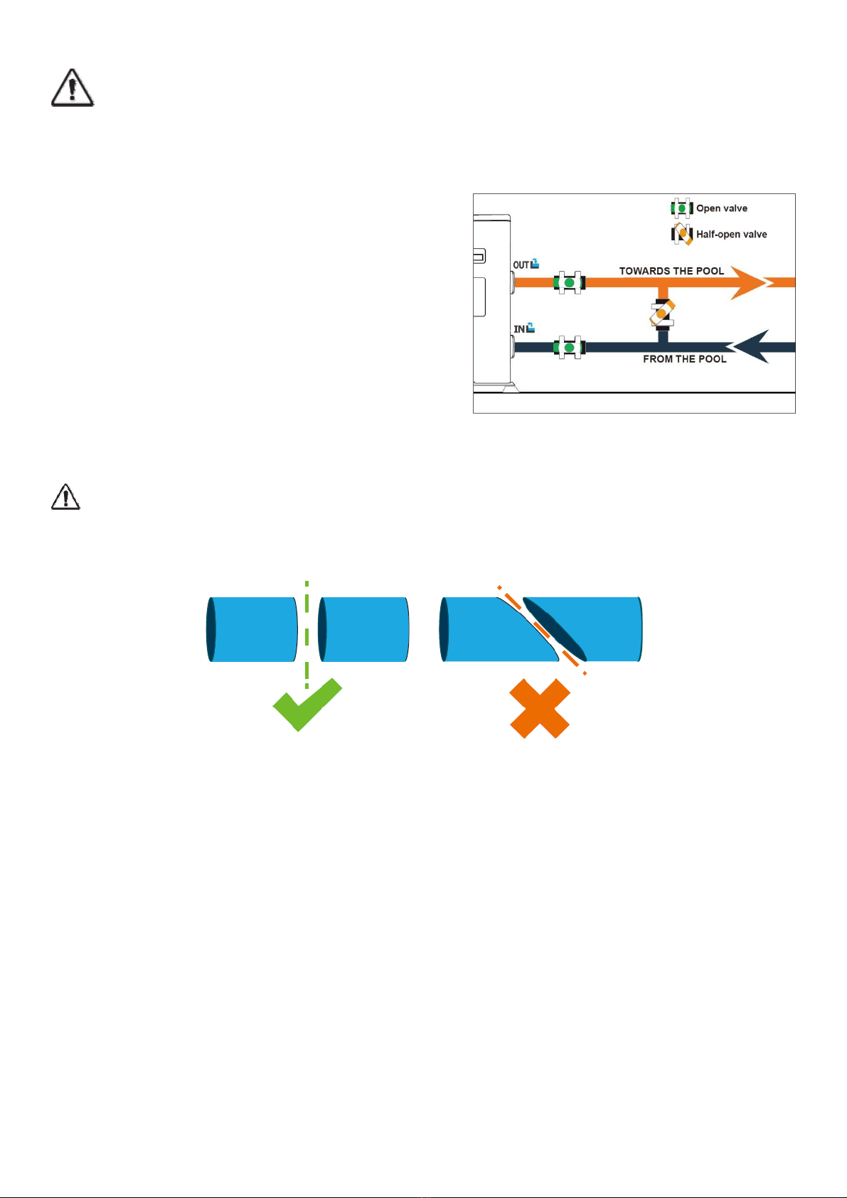
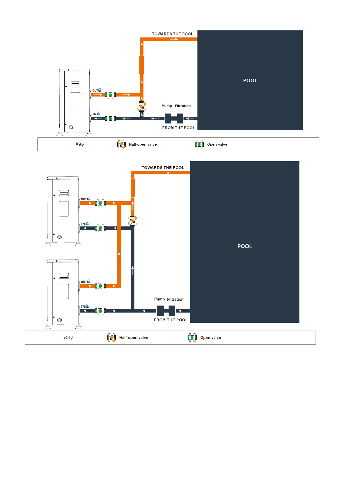
3.6 Hydraulic connection........................................................................................................................................................ 12
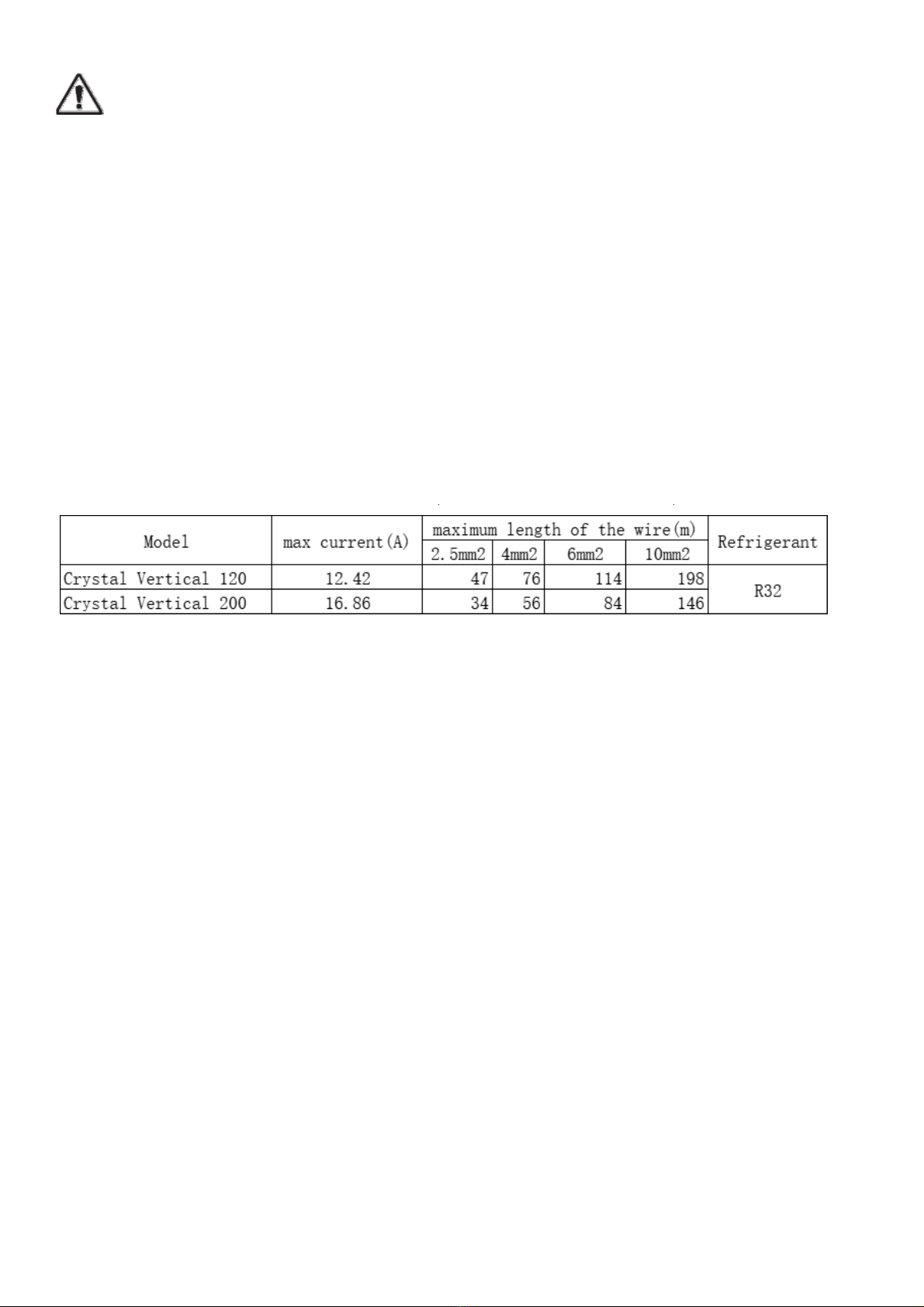
3.7 Electrical installation......................................................................................................................................................... 14
3.8 Electrical connection.........................................................................................................................................................15
4.
Use.................................................................................................................................................................................................16
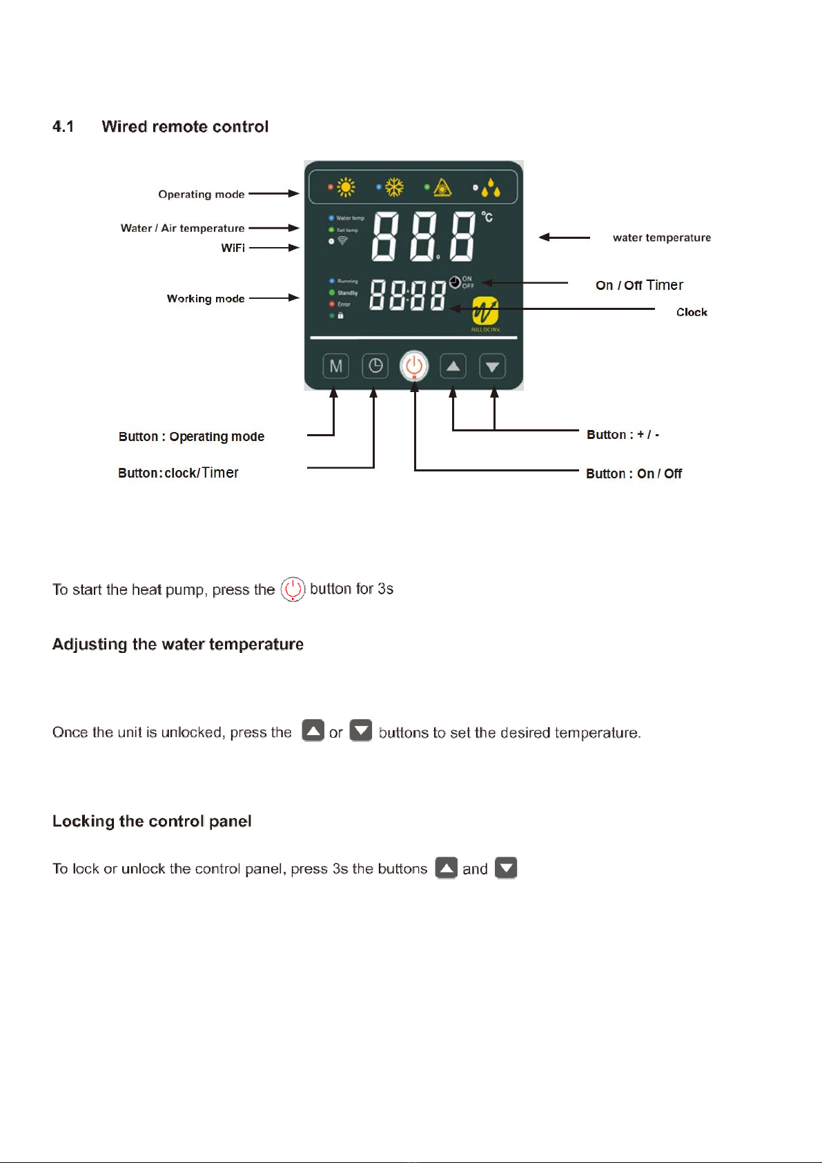
4.1 Wired remote control........................................................................................................................................................ 16
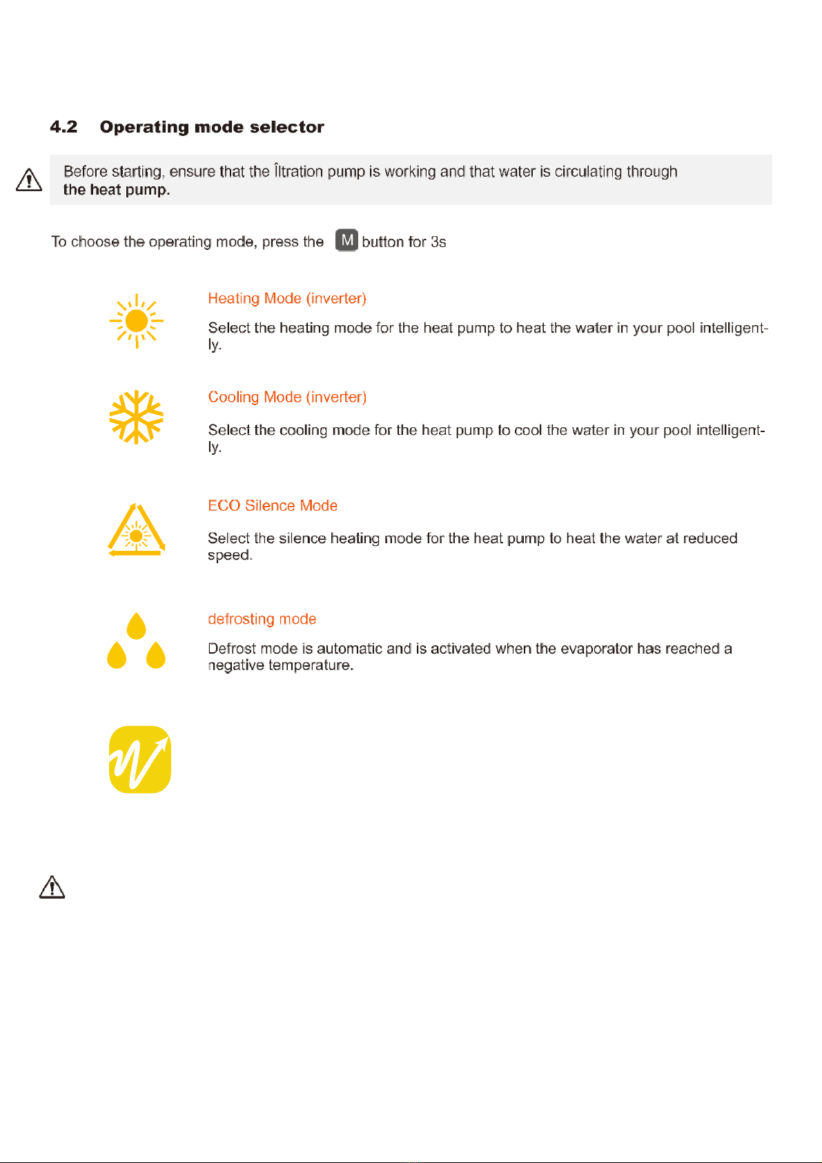
4.2 Operating mode selector..................................................................................................................................................17
4.3 Setting the clock................................................................................................................................................................ 18
4.4 Programming Start/Stop.................................................................................................................................................. 18
4.5 Activating a program.........................................................................................................................................................18
4.6 Forced de-icing function...................................................................................................................................................19
4.7 Enable / Disable LEDs..................................................................................................................................................... 19
4.8 Status values......................................................................................................................................................................20
4.9 System parameter query..................................................................................................................................................21
5.
Operation..................................................................................................................................................................................... 23
5.1 Operation............................................................................................................................................................................23
5.2 Using the pressure gauge................................................................................................................................................24
6.
Maintenance and servicing.....................................................................................................................................................25
6.1 Maintenance and servicing..............................................................................................................................................25
6.2 Winter storage................................................................................................................................................................... 26
7.
Repairs......................................................................................................................................................................................... 27
7.1 Breakdowns and faults..................................................................................................................................................... 27
7.2 List of faults........................................................................................................................................................................ 28
8.
Wiring diagram........................................................................................................................................................................... 29

4
1. General
1.1 General Terms of Delivery
All equipment, even if shipped ‘free of carriage and packing’, is dispatched at the consignee’s own risk
The person responsible for receiving the equipment must carry out a visual inspection to identify any dam- age to
the heat pump during transport (refrigerant system, body panels, electrical control box, frame). He/ she must note
down on the carrier’s delivery note any remarks concerning damage caused during transport and confirm them to
the carrier by registered letter within 48 hours.
The equipment must always be stored and transported vertically on a pallet and in its original packaging. If it is
stored or transported horizontally, wait at least 24 hours before switching it on.
1.2 Safety Instruction
WARNING: Please read carefully the safety instructions before using the equipment. The following
instructions are essential for safety so please strictly comply with them.
During installation and servicing
Only a qualified person may undertake installation, start-up, servicing and repairs, in compliance with
current standards.
Before operating or undertaking any work on the equipment (installation, commissioning, usage, servicing), the
person responsible must be aware of all the instructions in the heat pump’s installation manual as well as the
technical specifications.
Under no circumstances install the equipment close to a source of heat, combustible materials or a building’s air
intake.
If installation is not in a location with restricted access, a heat pump protective grille must be fitted.
To avoid severe burns, do not walk on pipe work during installation, repairs or maintenance.
To avoid severe burns, prior to any work on the refrigerant system, turn off the heat pump and wait several
minutes before placing temperature and pressure sensors. Check the refrigerant level when servicing the heat
pump.
Check that the high and low pressure switches are correctly connected to the refrigerant system and that
they turn off the electrical circuit if tripped during the equipment’s annual leakage inspection.
Check that there is no trace of corrosion or oil stains around the refrigerant components.

5
During use
To avoid serious injuries, never touch the fan when it is operating.
Keep the heat pump out of the reach of children to avoid serious injuries caused by the heat exchanger’s blades.
Never start the equipment if there is no water in the pool or if the circulating pump is stopped.
Check the water flow rate every month and clean the filter if necessary.
During cleaning
Switch off the equipment’s electricity supply.
Close the water inlet and outlet valves.
Do not insert anything into the air or water intakes or outlets. Do not rinse the equipment with water.
During repairs
Carry out work on the refrigerant system in accordance with current safety regulations.
Brazing should be performed by a qualified welder.
When replacing a defective refrigerant component, use only parts certified by our technical department.
When replacing pipe work, only copper pipes conforming to Standard NF EN12735-1 may be used for repairs.
When pressure-testing to detect leaks:
To avoid the risks of fire or explosion, never use oxygen or dry air. Use dehydrated nitrogen or a mixture of nitrogen
and refrigerant. The low and high side test pressure must not exceed 42 bar.
1.3 Water treatment
Heat pumps for swimming pools can be used with all types of water treatment systems.
Nevertheless, it is essential that the treatment system (chlorine, pH, bromine and/or salt chlorinator metering
pumps) is installed after the heat pump in the hydraulic circuit.
To avoid any deterioration to the heat pump, the water’s pH must be maintained between 6.9 and 8.0.

6
2. Description
2.1 Package contents
√Heat pump
√2 hydraulic inlet/outlet connectors (48/50mm diameter)
√This installation and user manual
√Condensation draining kit
√4 anti-vibration pads (fastenings not supplied)
2.2 General characteristics
A heat pump has the following features:
√CE certification and complies with the RoHS European directive.
√High performance with up to 90% energy savings compared to a conventional heating system.
√Clean, efficient and environmentally friendly R32 refrigerant.
√Reliable high output leading brand compressor.
√Wide hydrophilic aluminium evaporator for use at low temperatures. User-friendly intuitive remote control.
√Heavy duty ABS shell, anti-UV treated and easy to maintain. Designed to be silent.
√Dual antifreeze system to avoid frost damage:
Revolutionary exchanger with patented antifreeze system.
A smart monitoring system to preserve the pipe work and liner without emptying the pool in winter.

2.3 Technical Specification
Cr
y
stal Vertical Cr
y
stal Vertical
Ambient 15
℃
120 200
Advised pool volume m³ 35-50 60-80
Heating temperature range °C 25~40 25~40
Cooling temperature range °C 8~28 8~28
Auto mode temperature range
°C 5~43 5~43
Operating range °C -20~43 -20~43
Air 26°C Water 26°C Inverter mode
Capacity(KW) 13.00~3.04 20.93~5.23
Power input(KW) 1.94~0.24 3.22~0.46
Input current(A) 8.61~1.06 14.29~2.04
COP 12.67~6.70 11.37~6.50
Air 26°C Water 26°C Silent mode
Capacity(KW) 9.39~3.04 14.65~5.23
Power input(KW) 1.33~0.24 1.77~0.46
COP 12.67~7.06 11.37~8.29
Air 15°C Water 26°C Inverter mode
Capacity(KW) 9.63~2.23 15.50~3.88
Power input(KW) 2.10~0.32 3.39~0.57
Input current(A) 9.41~1.43 15.04~2.53
COP 6.96~4.59 6.80~4.57
Air 15°C Water 26°C Silent mode
Capacity(KW) 6.74~2.23 10.85~3.88
Power input(KW) 1.25~0.32 1.86~0.57
COP 6.96~5.39 6.80~5.83
Air 35°C Water 27°C
Capacity(KW) 7.25~2.93 10.85~5.03
Power input(KW) 2.04~0.63 2.58~1.05
Input current(A) 8.96~2.77 11.33~4.61
EER 4.65~3.55 4.77~3.56
Air-15°C Water26
℃
Capacity(KW) 4.33~1.00 6.95~1.75
Power input(KW) 1.995~0.304 3.221~0.542
Input current(A) 8.652~1.322 14.00~2.357
COP 3.29~2.17 3.23~2.17
Air -20°C Water 26°C
Capacity(KW) 2.41~0.56 3.88~0.97
Power input(KW) 1.89~0.288 3.051~0.513
Input current(A) 8.217~1.252 13.261~2.230
COP 1.94~1.28 1.89~1.27
Power supply 220-240V~ /50Hz
Max power input KW 2.8 3.8
Rated current(Air 15
℃
/Water 26
℃)
A
9.41~1.43
15.04~2.53
Max Current (correct)
A
12.42 16.86
Water flow m³/h 3.8 6.7
Refrigerant R32 R32
Min pressure/max pressure 1.5/4.15MPa 1.5/4.15MPa
Unit net dimensions mm 540*600*735 540*600*735
Package dimensions mm 976*665*865 576*685*865
Net weight kg 45 52
Gross weight kg 53 60
Noise at 1 m dB(A) 40~48 42~52
Noise at 10m dB(A) 21~29 24~32
compressor brand GMCC GMCC
compressor type Twin-Rotary Twin-Rotary
water proof level IPX4 IPX4
Loss charge (mCE) 1.1 1.1
Note: marked * specification only applicable to low temperature model.
7

8
D
C
2.4 Unit dimension
B
Crystal Vertical
120
Crystal Vertical
200
A
735
735
B570
570
C
550
550
D
540
540
E
600
600
F
414
414
G
87
87
H
160
160
Madeinmm
EA
F
GH

9
2.5 Exploding view
1Base Frame
12
Evaporator
2Electric Reactor
13
Motor Bracket
3Tray Heating Belt
14
4-way valve
4Electronic Expansive Valve
15
Electrical Control Box
5Compressor
16
Controller
6Heat Exchanger
17
Control Panel
7Water Flow Switch
18
Display Panel
8Fan Motor
19
Front Panel
9Fan Blade 20 Electric crankshaft heating
10 Top Cover 21 Electric base frame heating
11
Air Outlet Net

10
3. Installation
WARNING: Installation must be carried out by a qualified engineer.
This section is provided for information purposes only and must be checked and adapted if
necessary according to the actual installation conditions.
3.1 Pre-requirements
Equipment necessary for the installation of your heat pump:
Power supply cable suitable for the unit’s power requirements.
A By-Pass kit and an assembly of PVC tubing suitable for your installation as well as stripper, PVC adhesive.
A set of wall plugs and expansion screws suitable to attach the unit to your support.
Suitable fastening studs may be used to raise the unit.
3.2 Location
Please comply with the following rules concerning the choice of heat pump location.
- The unit’s future location must be easily accessible for convenient operation and maintenance.
- It must be installed on the ground, fixed ideally on a level concrete floor. Ensure that the floor is sufficiently
stable and can support the weight of the unit.
- A water drainage device must be provided close to the unit in order to protect the area where it isinstalled.
- If necessary, the unit may be raised by using suitable mounting pads designed to support its weight.
- Check that the unit is properly ventilated, that the air outlet is not facing the windows of neighbouring buildings
and that the exhaust air cannot return. In addition, provide sufficient space around the unit for servicing and
maintenance operations.
- The unit must not be installed in an area exposed to oil, flammable gases, corrosive products, sulphurous
compounds or close to high frequency equipment.
- To prevent mud splashes, do not install the unit near a road or track.
- To avoid causing nuisance to neighbours, make sure the unit is installed so that it is positioned towards the
area that is least sensitive to noise.
- Keep the unit as much as possible out of the reach of children.
≥0.5m ≥0.5m
≥ 0.5m ≥ 0.5m ≥0.5m ≥0.5m
Dimensions in mm.
Place nothing less than one metre in front of the heat pump.
Leave 50 cm of empty space around the sides and rear of the heat pump.
Do not leave any obstacle above or in front of the unit!
≥2.5
AIR

11
3.3 Installation layout
3.4 Installing the unit
While operating, the heat pump is subject to condensation. This will result in a more or less large run-off of
water, depending on the degree of humidity.
Install the heat pump, raising it at least 10 cm with solid water-resistant pads, then connect the drainage pipe to
the opening located under the pump.
*IN Winter USE* -DO NOT Connect the drainage pipe when using the heat pump in the winter, as this will allow the
water to freeze and block the tube. This will then allow water and ice to back up into the unit and cause damage which
will not be covered under the Warranty.
Please allow unrestricted run off of the condensate from the unit and to escape freely.
3.5 Installing the unit on noise-damping supports
In order to minimize the noise pollution associated with heat pump vibrations, it can be positioned on vibration
absorbing pads.
To do this, you simply have to position a pad between each of the unit’s feet and its support, and then fix
the heat pump to the support with suitable screws.

12
WARNING: Installation must be carried out by a qualified engineer.
This section is provided for information purposes only and must be checked and adapted if
necessary according to the actual installation conditions.
3.6 Hydraulic connection
By-Pass assembly
The heat pump must be connected to the pool by means of a
By-Pass assembly.
A By-Pass is an assembly consisting of 3 valves that
regulate the flow circulating in the heat pump.
During maintenance operations, the By-Pass permits the heat
pump to be isolated from the system without interrupting your
installation.
Making a hydraulic connection with the By-Pass kit
WARNING: Do not run water through the hydraulic circuit for 2 hours after applying the adhesive.
Step 1: Take the necessary steps to cut your pipes.
Step 2: Make a straight perpendicular cut through the PVC pipes with a saw.
Step 3: Assemble your hydraulic circuit without connecting it in order to check that it perfectly fits your installation,
then dismantle the pipes to be connected.
Step 4: Chamfer the ends of the cut pipes.
Step 5: Apply pipe and connections cleaner to the ends of the pipes and fittings, to be connected so both are
cleaned before gluing.
Step 6: Apply the adhesive in the same place.
Step 7: Assemble the pipe and fittings.
Step 8: Clean off any adhesive remaining on the PVC.
Step 9: Leave to dry for at least 2 hours before putting the hydraulic circuit into water.

13
By-Pass assembly for one heat pump
By-Pass assembly for more than one heat pump
The filter located downstream of the heat pump must be regularly cleared so that the water in the
system is clean, thus avoiding the operational problems associated with dirt or clogging in the filter.

WARNING: Installation must be carried out by a qualified engineer.
This section is provided for information purposes only and must be checked and adapted if
necessary according to the actual installation conditions.
3.7 Electrical installation
To function safely and maintain the integrity of your electrical system, the unit must be connected to a general
electricity supply in accordance with the following regulations:
Upstream, the general electricity supply must be protected by a 30 mA differential switch.
The heat pump must be connected to a suitable D-curve circuit breaker (see table below) in accordance with
current standards and regulations in the country where the system is installed.
The electricity supply cable must be adapted to match the unit’s rated power and the length of wiring required by
the installation (see table below). The cable must be suitable for outdoor use.
For a three-phase system, it is essential to connect the phases in the correct sequence. If the phases are
inverted, the heat pump’s compressor will not work.
In places open to the public, it is mandatory to install an emergency stop button close to the heat pump.
14

3.8 Electrical connection
WARNING: The heat pump’s power supply MUST be disconnected before any operation.
Please comply with the following instructions to electrically connect the heat pump.
Step 1: Detach the electrical side panel with a screwdriver to access the electrical terminal block.
Step 2: Insert the cable into the heat pump unit by passing it through the opening provided for that purpose.
Step 3: Connect the power supply cable to the terminal block in accordance with the diagram below.
Step 4: Carefully close the heat pump panel.
15

16
4. Use

17
4. Use
Auto mode
Automatic cooling or heating according to the set temperature.
Useful information
WARNING:When the cooling mode switches to heating mode or vice-versa,the heat pump will
restart after 10 minutes.
When the incoming water temperature is less than or equal to the required temperature(set point tempera-
ture -1℃),the heat pump will switch to heating mode.The compressor will stop when the temperature of
the incoming water is greater than or equal to the required temperature(set point temperature +1℃).

18
M
4. Use
4.3
Setting the clock
Set the system clock to local time, as follows:
Step 1: Press to set the time, the hours are blinking.
Step 2: Adjust the hours with the buttons
and
Step 3: Press to switch to minutes.
Step 4: Adjust the minutes with the buttons
and
.
Step 5: Press to validate and return to the main screen.
4.4
Programming Start/Stop
This function is for programming the Start/Stop timing. You can program up to 3 different Start/Stop timings. Setting is
as follows:
Step 1: Long press 3s to enter into timer functions
Step 2: Select the program to be configured with
M
thebuttons
and .
Step 3: Press to program the start time.
Step 4: Adjust the hours with the buttons
and
.
Step 5: Press to switch to minutes.
Step 6: Adjust the minutes with the buttons
and
.
Step 7: Press to program the stop time.
Step 8: Adjust the hours with the buttons
and
.
Step 9: Press to switch to minutes.
Step 10: Adjust the minutes with the buttons
and
.
Step 11: Press to return to the main screen.
4.5
Activating a program
Once the program has been defined, it can be activated as follows:
Step 1: Long press 3s to enter into timer functions
Step 2: Select the program to be activated with the buttons and .
Step 3: Keep pressing until the ON/OFF indicator lights are displayed and start flashing.
Step 4:MPress to return to the main screen.
The flashing ON/OFF lights indicate an active program.
NB: The remote control
returns automatically to
the main screen after 10
seconds.

19
M
4. Use
4.6
Forced de-icing function
Long and 3 seconds to enter forced de-icing, the symbol flashes.
4.7
Enable / Disable LEDs
Hold
and for 3 seconds to activate or deactivate the front LEDs. The LEDs are reactivated
automatically after a power cut.
M
This manual suits for next models
1
Table of contents
Other Crystal Heat Pump manuals
Popular Heat Pump manuals by other brands

York
York YZF installation manual

Dimplex
Dimplex SI 50TU Installation and operating instruction

Daikin
Daikin CHYHBH05AA installation manual

Zodiac
Zodiac Z550iQ Instructions for installation and use

Climate Control
Climate Control CLIMATE CONTROL CC-HTSTB Technical guide

Lennox
Lennox NEOSYS NAC 200 Application guide