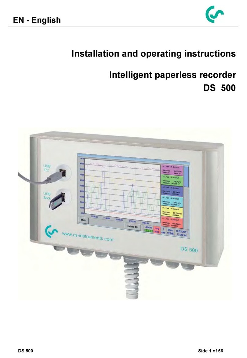
CS Instruments DS 500 User manual

DS 500 V1.55 Page 1 of 124
EN - English
Installation and operating instructions
Intelligent paperless recorder
DS 500

Foreword
DS 500 V1.55 Page 2 of 124
I. Foreword
Dear customer,
thank you very much for deciding in favour of the DS 500. Please read this installation
and operation manual carefully before mounting and initiating the device and follow
our advice. A riskless operation and a correct functioning of the DS 500 are only
guaranteed in case of careful observation of the described instructions and notes.
Sales Office South/Geschäftsstelle Süd
Zindelsteiner Str. 15
D-78052 VS-Tannheim
Tel.: +49 (0) 7705 978 99 0
Fax: +49 (0) 7705 978 99 20
Mail: [email protected]
Web: http://www.cs-instruments.com
Sales Office North/Geschäftsstelle Nord
Am Oxer 28c
D-24955 Harrislee
Tel.: +49 (0) 461 700 20 25
Fax: +49 (0) 461 700 20 26
Web: http://www.cs-instruments.com

Table of contents
DS 500 V1.55 Page 3 of 124
II. Table of contents
I. Foreword ....................................................................................................................... 2
II. Table of contents....................................................................................................... 3
1Safety instructions........................................................................................................ 7
1.1 General..................................................................................................................................... 7
1.2 Installation ............................................................................................................................... 8
2Application area...........................................................................................................10
3Intended use.................................................................................................................11
4Technical data DS 500.................................................................................................12
5Input signal...................................................................................................................13
6Cable cross-section.....................................................................................................13
7Package dimensions ...................................................................................................14
8Assembly instructions.................................................................................................15
9Panel and wall mounting.............................................................................................16
10 Connection diagrams DS 500 ..................................................................................17
10.1 DS 500 with 4 channels..................................................................................................... 17
10.2 DS 500 with 8 channels..................................................................................................... 17
10.3 DS 500 with 12 channels................................................................................................... 18
10.4 Power supply DS 500 standard version 100 - 240 VAC ................................................. 18
10.5 X2.1 and X2.2 by standard version 100 - 240 VDC, wired ex works............................. 18
10.6 Power supply by special version 24 VDC....................................................................... 19
10.7 Connection 4 x alarm relay, max. 230 VAC, 6 A............................................................. 19
10.8 Connection bus systems X4.1 and S4.1 ......................................................................... 19
10.9 Connector pin assignment for all sensors XA.1 –XA.4, XB.1 –XB.4, XC.1 –XC.4.... 19
11 Connection diagrams of the different sensor types...............................................20
11.1 Connection CS dew point sensors, series FA 415/FA 300............................................ 20
11.2 Connection for dew point- and consumption sensors, series FA/VA 4xx .................. 21
11.3 Connection for dew point- and consumption sensors, series FA/VA 5xx .................. 22
11.3 Connection pulse sensors ............................................................................................... 23
11.4 Analogue two-, three-, and four-wire current signal...................................................... 24
11.5 Three- and four-wire power supply 0 - 1/10/30 VDC ...................................................... 27
11.6 Two-, three-, and four-wire connector pin assignments for PT100/PT1000/KTY81.... 28
11.7 Connection with RS485 .................................................................................................... 28

Table of contents
DS 500 V1.55 Page 4 of 124
12 Connect the DS 500 with a PC.................................................................................29
13 Operation DS 500......................................................................................................30
13.1 Main menu (Home) ............................................................................................................ 30
13.1.1 Initialization...................................................................................................................... 30
13.1.2 Main menu after initialization........................................................................................... 31
13.2 Shutdown ........................................................................................................................... 31
13.3 Settings .............................................................................................................................. 32
13.3.1 Password settings............................................................................................................ 32
13.3.2 Sensor settings................................................................................................................ 33
13.3.2.1 Choice of the sensor type (For example type CS-Digital sensor) ............................ 33
13.3.2.2 Label and setting the description fields .................................................................... 36
13.3.2.3 Name the measurement data and define the decimal places.................................. 36
13.3.2.4 Recording measurement data.................................................................................. 37
13.3.2.5 Alarm settings........................................................................................................... 38
13.3.3 Dew point sensor with type CS-Digital (SDI Bus)............................................................ 40
13.3.4 Flow sensor VA 400 / VA 420 of type CS-Digital (SDI Bus)............................................ 41
13.3.4.1 More-Settings (scale analogue output) .................................................................... 42
13.3.5 Dew Point Sensor of type FA 5xx (RS 485 Modbus)....................................................... 45
13.3.5.1 Settings Dew point sensor FA 500 FA 510 .............................................................. 46
13.3.5.1.1 Unit selection for temperature and humidity...................................................................... 46
13.3.5.1.2 Definition of the System pressure (relative pressure value) .............................................. 46
13.3.5.1.3 Definition of Reference pressure (absolute pressure value).............................................. 47
13.3.5.1.4 Calibration......................................................................................................................... 48
13.3.5.1.5 More Settings Analogue output 4-20mA........................................................................... 48
13.3.6 Flow sensor of type VA 5xx (RS 485 Modbus)................................................................ 49
13.3.6.1 Settings for Flow sensor VA 5xx .............................................................................. 50
13.3.6.1.1 Diameter settings .............................................................................................................. 50
13.3.6.1.2 Gas Constant settings....................................................................................................... 51
13.3.6.1.3 Definition of the reference conditions ................................................................................ 52
13.3.6.1.4 Definition Unit of flow and velocity..................................................................................... 52
13.3.6.1.5 Definition consumption counter value and consumption unit............................................. 53
13.3.6.2 Settings analogue output 4-20mA of VA 5xx............................................................ 54
13.3.6.3 Settings Pulse / Alarm output of VA 5xx................................................................... 55
13.3.6.4 Settings ZeroPoint or Low Flow Cut off for VA 5xx.................................................. 56
13.3.7 Configuration of analogue sensors.................................................................................. 57
13.3.7.1 Type 0 - 1/10/30 Volt and 0/4 - 20 mA ................................................................... 57
13.3.7.2 Type PT100x and KTY81......................................................................................... 58
13.3.7.3 Type Pulse (Pulse ration)......................................................................................... 59
13.3.7.4 Type No Sensor........................................................................................................ 61
13.3.8 Typ Modbus..................................................................................................................... 62
13.3.8.1 Selection and activation of sensor type.................................................................... 62
13.3.8.2 Modbus settings ....................................................................................................... 62
13.3.9 Option Modbus extended channels................................................................................. 66
13.3.9.1 Activation of the extended Modbus channels........................................................... 66
13.3.9.2 Settings of the extended Modbus channels ............................................................. 66
13.3.9.3 Modbus Settings....................................................................................................... 67
13.3.10 Sensor Settings storing/importing (Custom Sensor).................................................... 68
13.3.10.1 Sensor Settings Storing........................................................................................... 68
13.3.10.2 Sensor Settings import ............................................................................................ 69

Table of contents
DS 500 V1.55 Page 5 of 124
13.4 Logger settings (data logger)........................................................................................... 70
13.5 Device settings.................................................................................................................. 74
13.5.1 Set language.................................................................................................................... 74
13.5.2 Date & Time..................................................................................................................... 74
13.5.3 Network settings .............................................................................................................. 75
13.5.4 ModBus settings (Slave).................................................................................................. 76
13.5.5 Relay Settings.................................................................................................................. 76
13.5.6 SD-Card........................................................................................................................... 77
13.5.7 Update System ................................................................................................................ 78
13.5.7.1 Saving System settings............................................................................................ 78
13.5.7.2 Update FW (Main and channel................................................................................. 79
13.5.8 Factory Reset................................................................................................................... 80
13.6 Report settings (optional)................................................................................................. 81
13.7 Virtual Channels (optional)............................................................................................... 82
13.7.1 Option „Virtual Channels“ activation ................................................................................ 82
13.7.2 Virtual Channels Settings ................................................................................................ 83
13.7.3 Selection of Sensor-type.................................................................................................. 83
13.7.4 Configuration of each single virtual value........................................................................ 85
13.7.4.1 Activation of a single virtual value ............................................................................ 85
13.7.4.2 Definition of Operands.............................................................................................. 85
13.7.4.3 Definition of Operations............................................................................................ 86
13.7.4.4 Definition of Unit ....................................................................................................... 87
13.7.4.5 Value name, resolution of decimal places and recording of values......................... 88
13.7.4.6 Calculation Example „Specific Performance“ .......................................................... 89
13.8 Analog Total (optional) ..................................................................................................... 91
13.8.1 Option „Analog Total“ activation ...................................................................................... 91
13.8.2 Selection of sensor type .................................................................................................. 92
13.9 Chart ................................................................................................................................... 93
13.10 Chart/Real time values...................................................................................................... 98
13.11 Channels .......................................................................................................................... 100
13.12 Real time values .............................................................................................................. 101
13.13 Alarm overview................................................................................................................ 102
13.14 Further setting options................................................................................................... 103
13.14.1 Set backlight............................................................................................................... 103
13.14.2 Calibrate touch-screen............................................................................................... 104
13.14.3 Cleaning..................................................................................................................... 104
13.14.4 System Status............................................................................................................ 104
13.14.5 About DS 500............................................................................................................. 105
13.15 Consumption report with cost settings, export data and webserver ........................ 106
13.15.1 Consumption report (optional).................................................................................... 106
13.15.2 Cost settings (optional) .............................................................................................. 108
13.16 Webserver (optional)....................................................................................................... 109
13.16.1 Option „Webserver“ activation.................................................................................... 109
13.16.2 Setup the Webserver Admin Password ..................................................................... 109
13.16.3 Webserver start.......................................................................................................... 110
13.16.3.1 Webserver assignment of rights (Administrator)................................................... 111
13.16.3.1.1 Accessrights Webserver................................................................................................ 111
13.16.3.1.2 Webserver Login ........................................................................................................... 111
13.16.3.1.3 New users and password defintion................................................................................ 112
13.16.3.2 Webserver E-Mail Configuration (Administrator).................................................. 113
13.16.3.3 Webserver MailOnAlarm (Administrator & Operator)............................................ 114
13.16.3.4 Webserver Chart (Administrator, Operator & User) .............................................. 115
13.16.3.5 Webserver Screen................................................................................................. 116
13.16.3.6 Webserver Actuals ................................................................................................ 117
13.16.3.7 Webserver Status.................................................................................................. 117

Table of contents
DS 500 V1.55 Page 6 of 124
13.17 Import / Export................................................................................................................. 118
13.17.1 Export Logger data..................................................................................................... 118
13.17.2 Screenshots export .................................................................................................... 119
13.17.3 Export System Settings.............................................................................................. 120
13.17.4 Export Report............................................................................................................. 120
13.17.5 Import system settings ............................................................................................... 121
14 Screenshot function...............................................................................................122
14.1 Screenshot saving .......................................................................................................... 122
15 Cleaning ..................................................................................................................123

Safety instruction
DS 500 V1.55 Page 7 of 124
1 Safety instructions
1.1 General
Warning!
Inadmissible operating parameters!
Undercutting and exceeding respectively of limit values may cause danger to persons
and material and may lead to functional and operational disturbances.
Measures:
•Make sure that the DS 500 is only operated within the admissible limit values indicated on the
type label.
•Strict observance of the performance data of the DS 500 in connection with the application.
•Do not exceed the admissible storage and transportation temperature.
Further safety instructions:
•Attention should also be paid to the applicable national regulations and safety instructions during
installation and operation.
•The DS 500 is not allowed to be used in explosive areas.
Additional remarks:
•Do not overheat the instrument!
•Change of battery or SD-Card are only allowed to be carried out by authorized qualified personnel.
and in strainless state!
Attention!
Malfunctions at the DS 500!
Faulty installation and insufficient maintenance may lead to malfunctions of the DS 500
which may affect the measuring results and which may lead to misinterpretations.
R
Please check whether this manual corresponds with the device type.
Please attend to all notes indicated in this instruction manual. It contains essential information
which has to be followed during installation, operation and maintenance. Therefore, this
instruction manual has to be read categorically by the technician as well as by the responsible
user/qualified personnel before installation, initiation and maintenance.
This instruction manual has to be available at any time at the operation site of the DS 500.
Regional and national regulations respectively, have to be observed in addition to this instruction
manual if necessary.
In case of any obscurities or questions with regard to this manual or the instrument please contact
CS Instruments GmbH.

Safety instructions
DS 500 V1.55 Page 8 of 124
1.2 Installation
Warning!
Supply voltage!
Contact with supply voltage carrying non-insulated parts may cause an electric shock
with injury and death.
Measures:
•Note all applicable regulations for electrical installations (e.g. VDE 0100)!
•Carry out maintenance only in strain less state!
•All electric works are only allowed to be carried out by authorized qualified personnel.
Danger!
Missing earth connection!
When the earth connection (protective earth) is missing, there is the
risk in the event of malfunction, that contactable, conductive
components may carry supply voltage. Touching of such parts leads
to an electric shock with injuries and death.
It is imperative to connect the plant to earth or to connect the
protective conductor according to the regulations.
Do not use plug adapters at the power plug.
Have the power plug replaced by qualified skilled persons, if
required.

Safety instructions
DS 500 V1.55 Page 9 of 124
The plug of the power supply cord is used as a separator. This separator must be clearly recognizable
and easily accessible by the user. A plug connector with a CEE7/7 system is necessary.
All the electrical lines carrying supply voltage or another voltage that is dangerous in the case of con-
tact (power supply cord, alarm and indicator relays), must additionally be equipped with double or
reinforced insulation (EN 61010-1). This can be ensured by using plastic-sheathed cables, a second
insulation (e.g. flexible insulating tubing), or correspondingly suitable lines with reinforced insulation.
The connecting cables can be equipped, for example, with flexible insulating tubing.
The additional flexible insulating tubing must withstand the electrical and mechanical stresses which
can occur during the intended use (see EN 61010-1, Clause 6.7.2.2.1).
DANGER!
Supply voltage!
When wiring the connecting lead, it must be ensured that the double or
reinforced insulation be-tween the electric circuits that are dangerous in the
case of contact and the contactable secondary circuit remains maintained.
NOTE!
The additional insulation must be suitable for a test voltage of 1500 V
alternating current.
The thickness of the insulation must be at least 0.016 inch.
E.g. flexible insulating tubing, type BIS 85 (Bierther GmbH).
The additional insulation of the connecting leads (mains connection, alarm and indicator relays) can
be implemented as follows:
3 2 1
(1) - Terminals (connectors)
(2) –Flexible insulating tubing for the connecting leads
(3) –Connecting cable

Application area
DS 500 V1.55 Page 10 of 124
2 Application area
Our long-term hands-on experience in measurement and control technology was implemented in the
new DS 500.
From recording of the measured data, automatic sensor identification, indication on a big colour
screen, alerting, storage up to remote read-out via web server, all that is possible with DS 500. By
means of the CS-Soft, software alarms can be sent via SMS or e-mail.
On the big 7' colour screen with touch panel all information is available at a glance.
The operation is very easy. All measured values, measured curves and threshold exceeding’s are
indicated. The progression of the curve, since the beginning of the measurement, can be viewed by
an easy slide of the finger.
Daily, weekly and monthly reports, with costs in € and counter reading in m
3
, for each consumption
sensor are completing the sophisticated system concept.
The huge difference to ordinary paperless chart recorders reveals in the easy initiation as well as in
the evaluation of the measured data. All sensors are identified directly and powered by DS 500.
Everything is matched and tuned.
Versatile:
Up to 12 sensors, incl. all CS sensors
(consumption, dew point, pressure, current,
KTY, PT 100, PT 1000) are identified auto-
matically by DS 500. Optional analogue
sensors (0/4 - 20 mA, 0 - 1/10/30 V, pulse)
can be configured easily and quickly.
Digital sensors can be connected via
RS 485, Modbus RTU and SDI.
Flexible:
Network-compatible and
worldwide remote data
transmission via
Ethernet, integrated web
server.
Alarm relay / fault
indication:
Up to 32 threshold
values can be
configured freely and
allocated to 4 different
alarm relay. Collective
alarms are possible.

Intended use
DS 500 V1.55 Page 11 of 124
3 Intended use
The DS 500 data logger serves for the stationary measured data acquisition and storage of analogue
and digital input signals.
The DS 500 data logger is exclusively designed and constructed for the proper application purpose that
is described herein and must only be used correspondingly.
A check in order to ascertain whether or not the device is suitable for the chosen employment must be
carried out by the user. It must be ensured that the medium is compatible with the components which
come into contact with it. The technical data listed in the data sheet are binding.
Improper handling or operation outside the technical specifications is impermissible. Claims of any kind
on the basis of improper use are excluded.

Technical data DS 500
DS 500 V1.55 Page 12 of 124
4 Technical data DS 500
Dimensions of housing
280 x 200 x 95 mm
Connections
18 x PG 12 for sensors and supply, alarm relay
1 x RJ 45 Ethernet connection
Version panel mounting
Cutout panel 250 x 156 mm
Weight
3,5 kg
Material
Die cast metal, front screen polyester
Protection level
IP65
Sensor inputs
4/8/12 sensor inputs for analogue and digital sensors
freely allocatable.
Digital CS sensors for dew point and consumption with SDI interface
FA/VA 400 Series.
Digital third-party sensors RS 485/Modbus RTU, other bus systems
realizable on request.
Analogue CS sensors for pressure, temperature, clamp-on
ammeters preconfigured.
Analogue third-party sensors 0/4 –20 mA, 0 - 1/10/30 V, pulse,
Pt100/Pt1000, KTY.
Power supply for sensors
Output voltage: 24 VDC ± 10% galavanically isolated
Output current: 130 mA by continuous operation, peak 180mA
Maximum output current over all channels with
- one power supply: 400mA
- two power supplies: 1Ampere
Interfaces
USB stick, USB cable, Ethernet/RS 485 Modbus RTU/TCP,
SDI other bus systems on request, web server optionally
Outputs
Outputs 4 relay (max. switching voltage: 400 VAC / 300 VDC, Switching
current: min. 10mA, max. 6A) alarm management,
relay freely programmable, collective alarm.
Analogue output, pulse in case of sensors with own signal
output looped, like e. g. VA/FA Series.
Memory card
Memory size 2 GB SD memory card standard, optionally up to 4 GB
Power supply
100 - 240 VAC/50 - 60 Hz, 75VA , special version 24 VDC
Battery 1)
CR 2032
Colour screen
7" touch panel TFT transmissive, graphics, curves, statistics
Accuracy
See sensor specifications
Operating temperature
0 - 50 °C
Storage temperature
-20 - 70 °C
Optionally
Web server
Optionally
Quick measurement with 10 ms sampling rate for analogue sensors,
Max/Min indication per second.
Optionally
Option "consumption report” statistics, daily/weekly/monthly report.
1) Lithium manganese dioxide Battery, Panasonic CR2032 / 3 V / 225 mAh

Input signal/Cable cross-section
DS 500 V1.55 Page 13 of 124
5 Input signal
6 Cable cross-section
6.1 Power supply 100 - 240 VAC, 50 - 60 Hz, special version 24 VDC:
Cable cross section power supply: 0,75 mm²
6.2 Sensor circuit points/Output signal:
AWG16 –AWG28, cable cross-sections: 0,14 - 1,5 mm2
Cable gland clamping Range: 4-8mm
Input signal
Current signal
(0 –20 mA / 4 –20 mA)
internal or external
power supply
Measuring range
0 –20 mA / 4 –20 mA
Resolution
0,0001 mA
Accuracy
0,03 mA 0,05 %
Input resistance
50
Voltage signal
(0 - 1V)
Measuring range
0 - 1 V
Resolution
0,05 mV
Accuracy
0,2 mV 0,05 %
Input resistance
100 k
Voltage signal
(0 - 10 V / 30 V)
Measuring range
0 - 10 V/30 V
Resolution
0,5 mV
Accuracy
2 mV 0,05 %
Input resistance
1 M
RTD
Pt100
Measuring range
-200 - 850 °C
Resolution
0,1 °C
Accuracy
0,2 °C at -100 - 400 °C
0,3 °C (further range)
RTD
Pt1000
Measuring range
-200 - 850 °C
Resolution
0,1 °C
Accuracy
0,2 °C at -100 - 400 °C
0,3 °C ( further range )
Pulse
Measuring range
Minimum pulse length 100
μ
s
frequency 0 - 1 kHz
max. 30 VDC

Package dimensions
DS 500 V1.55 Page 14 of 124
7 Package dimensions
Dimensions of holes for wall mounting (D = 6 mm):

Assembly instructions
DS 500 V1.55 Page 15 of 124
8 Assembly instructions

Panel and wall mounting
DS 500 V1.55 Side 16 of 124
9 Panel and wall mounting
Cut-out panel
Dimension of housing 270 x 170 x 90 mm
Dimension of holes for wall mounting D = 6 mm

Connection diagrams DS 500
DS 500 V1.55 Side 17 of 124
10 Connection diagrams DS 500
10.1 DS 500 with 4 channels
123
123
12345
1 2 3 4 5 6 7 8 9
12345678
9
123
123
1
23
12345
12345
12345678
9
1 2 3 4 5 6 7 8 9
X3.4 X3.3 X3.2 X3.1
X2.2 X2.1 X1.1
X4.1
XA.4 XA.3
XA.1 XA.2
ON 1 2 3 4 5 6 7 8
S4.1
X1.1:
power supply
X2.1, X2.2:
for internal use
X3.1 - X3.4:
alarm relay 1 –4
X4.1, S4.1:
for CAN, RS485,
R120 configuration
XA.1 - XA.4:
sensor channels 1 –4
10.2 DS 500 with 8 channels
123
123
12345
1 2 3 4 5 6 7 8 9
12345678
9
123
123
1
23
12345
12345
12345678
912345678
912345678
912345678
9
12345678
9
1 2 3 4 5 6 7 8 9
X3.4 X3.3 X3.2 X3.1
X2.2 X2.1 X1.1
X4.1
XB.4 XB.3 XB.2 XB.1
XA.4 XA.3
XA.1 XA.2
X1.1:
power supply
X2.1, X2.2:
for internal use
X3.1 - X3.4:
alarm relay 1 –4
X4.1:
for CAN, RS485,
R120
configuration
XA.1 - XA.4:
sensor channels
1 –4
XB.1 - XB.4:
sensor channels
5 –8

Connection diagrams DS 500
DS 500 V1.55 Side 18 of 124
10.3 DS 500 with 12 channels
123
123
12345
1 2 3 4 5 6 7 8 9
12345678
9
123
123
1
23
12345
12345
12345678
912345678
912345678
912345678
9
12345678
912345678
912345678
912345678
9
12345678
9
1 2 3 4 5 6 7 8 9
X3.4 X3.3 X3.2 X3.1
X2.2 X2.1 X1.1
X4.1
XB.4 XB.3 XB.2 XB.1
XC.4 XC.3 XC.2 XC.1
XA.4 XA.3
XA.1 XA.2
X1.1:
power supply
X2.1, X2.2:
for internal use
X3.1 - X3.4:
alarm relay 1 –4
X4.1:
for CAN, RS485, R120
configuration
XA.1 - XA.4:
sensor channels 1 –4
XB.1 - XB.4:
sensor channels 5 –8
XC.1 - XC.4:
sensor channels 9 –12
10.4 Power supply DS 500 standard version 100 - 240 VAC
X1.1
L1
N
PE
100 - 240 VAC, 50 - 60 Hz
10.5 X2.1 and X2.2 by standard version 100 - 240 VDC, wired ex works
X2.1, X2.2
L1´
N´
PE´
GND
U+ (24 VDC)
Only for internal use

Connection diagrams of the different sensor types
DS 500 V1.55 Side 19 of 124
10.6 Power supply by special version 24 VDC
X2.1
GND
U+ (24 VDC)
External supply 24 VDC (X 2. 2 not occupied)
Internal power supplies 100 - 240 VAC/24 VDC are not assembled.
The supply voltage 24 VDC connect directly into pin 4 and 5.
10.7 Connection 4 x alarm relay, max. 230 VAC, 6 A
X3.1 –X3.4
NC
COM
NO
X3.1: alarm relay 1
X3.2: alarm relay 2
X3.3: alarm relay 3
X3.4: alarm relay 4
NC and COM are closed by: alarm, voltage breakdown, sensor
break
10.8 Connection bus systems X4.1 and S4.1
X4.1
A (+)
B (-)
GND
Y
Z
S4.1
RS485 Modbus S2, S3, S7 ON
TERMINATING 120R S1, S8 ON
DS 500 version with
4 channels
10.9 Connector pin assignment for all sensors XA.1 –XA.4, XB.1 –XB.4, XC.1 –XC.4
XA.1 –XA.4
XB.1 –XB.4
XC.1 –XC.4
I (500µA)
12345678
+ RS485
- RS485
SDI
Analog IN +
+VB 24Vdc
-VB GND
Analog IN -
9
Ext.
Anzeige
RS485-A (+)
RS485-B (-)
SDI (CS-internal data transfer for all dew point and consumption sensors)
ANALOGUE IN + (current signal and voltage signal)
ANALOGUE IN –(current signal and voltage signal)
CURRENT SOURCE 500 µA
+VB, 24V DC sensor power supply
- VB-, GND sensor
- Support Pin for ext. use e.g. PLC/ZLT or Display

Connection diagrams of the different sensor types
DS 500 V1.55 Page 20 of 124
11 Connection diagrams of the different sensor types
By/With consumption sensors and dew point sensors from CS Instruments there is the possibility to provide
values as analogue current signal 4 –20 mA for further working process.
The measurement/reading of the current signal for an external PLC/ZLT or external third-party display is
explained in the connection diagrams.
BY using of the CS Instruments connection cables 0553.0104 or 0553.0105 please follow pining:
Pin 1
Pin 2
Pin 3
Pin 4
Pin 5
Connector VA / FA 4xx
SDI
- VB
+ VB
+I 4…20mA
NC
Connector VA / FA 5xx
+ VB
Modbus A
- VB
Modbus B
+I 4…20mA
Connection cable
0553.0104 (5m)
0553.0105 (10m)
brown
white
blue
black
grey
The following connection diagrams in Chapter 10 apply to XA.1 to XC.4!
FA serial: dew point sensors from CS Instruments
VA serial: consumption sensors from CS Instruments
11.1 Connection CS dew point sensors, series FA 415/FA 300
1
3 2
SDI
+-
Sensor
I (500µA)
12345678
+ RS485
- RS485
SDI
Analog IN +
+VB 24Vdc
-VB GND
Analog IN -
9
Ext.
Anzeige
ß+4 ...20mA
DS 500
FA 300
FA 415
The digital data transmission between DS 500 and the dew point
sensors FA 415 and FA 300 occur via the SDI bus line.
.
à+4 ...20mA
3
SDI
1
2
Sensor extern
SPS, ZLT
4 .. 20 mA
+-
I (500µA)
12345678
+ RS485
- RS485
SDI
Analog IN +
+VB 24Vdc
-VB GND
Analog IN -
9
Ext.
Anzeige
DS500 with ext. 4 -20mA routing
It´s possible to connect the FA 300/FA 425 alternatively as 4 –20 mA
analogue sensor in 2-wire technology.
To route the current signal of 4 - 20 mA to an external display, PLC or
ZLT, please remove the bridge from Pin 4 (Analog IN) to support Pin
9 (ext. display) and then connect the external display according
schematic.
Other manuals for DS 500
2
This manual suits for next models
1
Table of contents
Other CS Instruments Voice Recorder manuals
