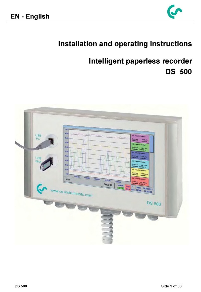
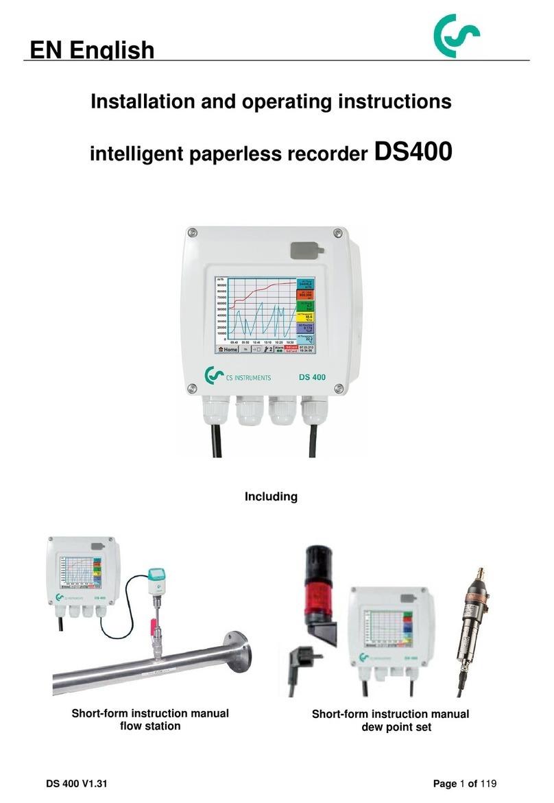
CS Instruments DS400 User manual

DS 400 mobile V1.29 Seite 1von 109
Installation and operating instructions
intelligent paperless recorder
DS400 mobile
EN English

Foreword
DS 400 mobile V1.29 Seite 2von 109
I. Foreword
Dear customer,
thank you very much for deciding in favour of the DS 400. Please read this
installation and operation manual carefully before mounting and initiating the device
and follow our advice. A riskless operation and a correct functioning of the DS 400
are only guaranteed in case of careful observation of the described instructions and
notes
Sales Office South / Geschäftsstelle Süd
Zindelsteiner Str. 15
D-78052 VS-Tannheim
Tel.: +49 (0) 7705 978 99 0
Fax: +49 (0) 7705 978 99 20
Web: http://www.cs-instruments.com
Sales Office North / Geschäftsstelle Nord
Am Oxer 28c
D-24955 Harrislee
Tel.: +49 (0) 461 700 20 25
Fax: +49 (0) 461 700 20 26
Web: http://www.cs-instruments.com

Table of Contents
DS 400 mobile V1.29 Seite 3von 109
II. Table of Contents
I. Foreword....................................................................Fehler! Textmarke nicht definiert.
II. Table of Contents.........................................................................................................3
1Safety instructions ..........................................................................................................6
1.1 Generell................................................................................................................................... 6
1.2 Installation .............................................................................................................................. 7
1.3 Lithium Ion Battery ................................................................................................................ 7
2Application area...............................................................................................................8
3Intended use.....................................................................................................................9
4Technical data DS 400...................................................................................................10
5Input signal.....................................................................................................................11
6Cable cross-section.......................................................................................................11
6.1 Sensor circuit points/Output signal................................................................................... 11
7Connection diagrams of the different sensor types...................................................12
7.1 Connector pin assignment for all sensors A1 –A2, B1 –B2 .......................................... 12
7.2 Connection diagrams .......................................................................................................... 13
7.2.1 Anschluss CS Taupunktsensoren Serie FA 415/FA 300................................................. 13
7.2.2 Connection for dew point- and consumption sensors, serial FA/VA 400........................ 13
7.2.3 Connection for dew point- and consumption sensors, series FA/VA 5xx........................ 13
7.2.4 Connection pulse Sensors............................................................................................... 14
7.2.5 Analogue two-, three-, and four-wire current signal......................................................... 15
7.2.6 Three- and four-wire power supply 0 - 1/10/30 VDC....................................................... 16
7.2.7 Two-, three- and four-wire connector pin assignments for PT100/PT1000/KTY81........ 17
7.3 Connection with RS485....................................................................................................... 17
8Connect the DS 400 with a PC......................................................................................18

Table of contents
DS 400 mobile V1.29 Seite 4von 109
9Operation DS 400...........................................................................................................19
9.1 Switching on / off of the DS400 mobile.............................................................................. 19
9.2 Main menu (Home)............................................................................................................... 19
9.2.1 Initialization...................................................................................................................... 19
9.2.2 Main menu after initialization........................................................................................... 20
9.3 Settings................................................................................................................................. 21
9.3.1 Password-Settings........................................................................................................... 21
9.3.2 Sensor-Settings ............................................................................................................... 22
9.3.2.1 Choice of the sensor type (For example type CS-Digital sensor)............................ 23
9.3.2.2 Name the measurement data and define the decimal places.................................. 24
9.3.2.3 Recording measurement data.................................................................................. 24
9.3.2.4 Alarm-Settings.......................................................................................................... 25
9.3.2.5 More Settings (scale analogue output)..................................................................... 27
9.3.2.6 Dew Point Sensor FA 400 / FA 410 of type CS-Digital (SDI Bus)............................ 28
9.3.2.7 Flow sensor VA 400 / VA 420 of type CS-Digital (SDI Bus)..................................... 29
9.3.2.8 Dew Point Sensor FA 500 / FA 510 of type FA 5xx (RS 485 Modbus).................... 32
9.3.2.8.1 Settings Dew point sensor FA 500 FA 510 .......................................................... 33
9.3.2.8.1.1 Unit selection for temperature and humidity................................................... 33
9.3.2.8.2 Definition of the System pressure (relative pressure value)................................. 33
9.3.2.8.3 Definition of Reference pressure (absolute pressure value)............................... 34
9.3.2.8.4 Calibration ............................................................................................................ 35
9.3.2.8.5 More Settings Analogue output 4-20mA ............................................................ 35
9.3.2.9 Flow sensor of type VA 5xx (RS 485 Modbus)......................................................... 36
9.3.2.9.1 Settings for Flow sensor VA 5xx .......................................................................... 37
9.3.2.9.1.1 Diameter settings ........................................................................................... 37
9.3.2.9.1.2 Gas Constant settings.................................................................................... 38
9.3.2.9.1.3 Definition of the reference conditions............................................................. 39
9.3.2.9.1.4 Definition Unit of flow and velocity ................................................................. 39
9.3.2.9.1.5 Definition consumption counter value and consumption unit......................... 40
9.3.2.9.2 Settings analogue output 4-20mA of VA 5xx........................................................ 41
9.3.2.9.3 Settings Pulse / Alarm output of VA 5xx............................................................... 42
9.3.2.9.4 Settings ZeroPoint or Low Flow Cut off for VA 5xx.............................................. 44
9.3.2.10 Configuration of Analogue-Sensors ......................................................................... 45
9.3.2.10.1 Type 0 - 1/10/30 Volt und 0/4 –20 mA................................................................. 45
9.3.2.10.2 Type PT100x and KTY81..................................................................................... 47
9.3.2.10.3 Type Pulse (Pulse ration)..................................................................................... 48
9.3.2.10.4 Type „No Sensor“ ................................................................................................. 50
9.3.2.11 Type Modbus............................................................................................................ 51
9.3.2.11.1 Selection and activation of Sensor-Type Modbus................................................ 51
9.3.2.11.2 Modbus Settings................................................................................................... 51
9.3.2.12 Custom Sensor......................................................................................................... 55
9.3.2.12.1 Sensor settings saving ......................................................................................... 55
9.3.2.12.2 Sensor settings import.......................................................................................... 56
9.3.3 Device Settings................................................................................................................ 57
9.3.3.1 Language.................................................................................................................. 57
9.3.3.2 Date & Time.............................................................................................................. 58
9.3.3.3 Network-Settings...................................................................................................... 59
9.3.3.4 Relay Settings .......................................................................................................... 60
9.3.3.5 SD-Card.................................................................................................................... 61
9.3.3.6 System...................................................................................................................... 62
9.3.3.6.1 Save system settings............................................................................................ 62
9.3.3.6.2 System update...................................................................................................... 63
9.3.3.6.3 Check for Updates................................................................................................ 63
9.3.3.6.4 Update Firmware.................................................................................................. 64
9.3.3.6.5 Update Channels.................................................................................................. 64
9.3.3.6.6 Factory Reset....................................................................................................... 65
9.3.3.7 Calibrate touch-screen ............................................................................................. 66

Table of contents
DS 400 mobile V1.29 Seite 5von 109
9.3.4 Set backlight .................................................................................................................... 66
9.3.5 Cleaning........................................................................................................................... 67
9.3.6 System-Status.................................................................................................................. 67
9.3.7 About DS 400................................................................................................................... 67
9.3.8 Virtual Channels (optional) .............................................................................................. 68
9.3.8.1 Option „Virtual Channels“ activation......................................................................... 68
9.3.8.2 Virtual Channels Einstellung..................................................................................... 69
9.3.8.3 Selection of Sensor-type .......................................................................................... 69
9.3.8.4 Configuration of each single virtual value................................................................. 70
9.3.8.4.1 Activation of a single virtual value........................................................................ 70
9.3.8.4.2 Definition of Operands.......................................................................................... 71
9.3.8.4.3 Definition of Operations........................................................................................ 72
9.3.8.4.4 Definition of Unit................................................................................................... 72
9.3.8.5 Value name, resolution of decimal places and recording of values......................... 74
9.3.8.6 Calculation Example „Specific Performance“.......................................................... 75
9.3.9 Analog Total (optional)..................................................................................................... 77
9.3.9.1 Option „Analog Total“ activation ............................................................................... 77
9.3.9.2 Selection of sensor type........................................................................................... 78
9.3.10 Webserver (optional) ....................................................................................................... 79
9.3.10.1 Option „Webserver“ activation.................................................................................. 79
9.3.10.2 Setup the Webserver Admin Password.................................................................... 80
9.3.10.3 Webserver start........................................................................................................ 80
9.3.10.4 Webserver assignment of rights (Administrator)...................................................... 81
9.3.10.4.1 Accessrights Webserver....................................................................................... 81
9.3.10.5 Webserver Login ...................................................................................................... 81
9.3.10.6 New users and password......................................................................................... 82
9.3.10.7 Webserver E-Mail Configuration (Administrator)...................................................... 83
9.3.10.8 Webserver MailOnAlarm (Administrator & Operator)............................................... 84
9.3.10.9 Webserver Chart (Administrator, Operator & User) ................................................. 85
9.3.10.10 Webserver Screen................................................................................................... 86
9.3.10.11 Webserver Actuals .................................................................................................. 87
9.3.10.12 Webserver Status.................................................................................................... 87
9.3.11 Data Logger (optional)..................................................................................................... 88
9.3.11.1 Option „Data Logger“ activation................................................................................ 88
9.3.11.2 Data logger Settings................................................................................................. 88
9.4 Chart...................................................................................................................................... 92
9.5 Chart / Real time values....................................................................................................... 96
9.6 Channels............................................................................................................................... 98
9.7 Real time values................................................................................................................... 99
9.8 Alarm-Overview.................................................................................................................. 100
9.9 Export /Import..................................................................................................................... 101
9.9.1 Eport Logger data.......................................................................................................... 101
9.9.2 Export System Settings ................................................................................................. 103
9.9.3 Import System Settings.................................................................................................. 104
9.10 Screenshot function .......................................................................................................... 105
9.10.1 Screenshot saving......................................................................................................... 105
9.10.2 Screenshots export........................................................................................................ 106
10 Cleaning ....................................................................................................................108

Safety instructions
DS 400 mobile V1.29 Seite 6von 109
1 Safety instructions
1.1 Generell
Please check whether this manual corresponds with the device type.
Please attend to all notes indicated in this instruction manual. It contains essential information
that has to be followed during installation, operation and maintenance. Therefore, this instruction
manual has to be read categorically by the technician as well as by the responsible user/qualified
personnel before installation, initiation and maintenance.
This instruction manual has to be available at any time at the operation site of the DS 400.
Regional and national regulations respectively, have to be observed in addition to this instruction
manual if necessary.
In case of any obscuritiesor questions with regard to this manual or the instrument please contact
CS Instruments GmbH.
Warning!
Supply voltage!
Contact with supply voltage carrying non-insulated parts may cause an electric shock
with injury and death.
Measures:
•Note all applicable regulations for electrical installations (e.g. VDE 0100)!
•Carry out maintenance only in strain less state!
•All electric works are only allowed to be carried out by authorized qualified personnel.
Warning!
Inadmissible operating parameters!
Undercutting and exceeding respectively of limit values may cause danger to persons
and material and may lead to functional and operational disturbances.
Measures:
•Make sure that the DS 500 is only operated within the admissible limit values indicated on the
type label.
•Strict observance of the performance data of the DS 400 in connection with the application.
•Do not exceed the admissible storage and transportation temperature.
Further safety instructions:
•Attention should also be paid to the applicable national regulations and safety instructions during
installation and operation.
•The DS 400 is not allowed to be used in explosive areas.
Additional remarks:
•Do not overheat the instrument!
•Change of battery and SD-Card are only allowed to be carried out by authorized qualified personnel
and in strain less state
Attention!
Malfunctions at the DS 400!
Faulty installation and insufficient maintenance may lead to malfunctions of the DS 400
which may affect the measuring results and which may lead to misinterpretations.

Safety instructions
DS 400 mobile V1.29 Seite 7von 109
1.2 Installation
NOTE!
The plug of the power supply unit (charger) is used as a separator.
This separator must be clearly recognisable and easily accessible by the user. A
plug connector with a CEE7/7 system is necessary.
NOTE!
Only the supplied power supply may be used.
1.3 Lithium Ion Battery
Warning!
Battery!
The replacement of the battery must only be carried out by authorised and
skilled personnel, and when the device is de-energised.
Only the original battery of the manufacturer with built-in protection circuit
may be used
Do not use any other power supply for charging the Li-Ion battery as the provided.
Do not charge the battery under conditions that are not specified in the manual.
Do not charge the battery in an environment with flammable substances. Never charge the
battery unattended.
Transport
The contained lithium ion batteries are subject to the Dangerous Goods Legislation requirements. The user
can transport the batteries by road without further requirements.
When being transported by third parties (e.g.: air transport or forwarding agency), special requirements on
packaging and labelling must be observed. For preparation of the item being shipped, consulting an expert
for hazardous material is required.
Please also observe possibly more detailed national regulations.
Disposal
The datalogger, rechargeable batteries, accessories and packaging should be sorted for
environmental friendly recycling.
Do not dispose of power tools and batteries/rechargeable batteries into household waste!
Only for EC countries:
According to the European Guideline 2012/19/EU, power tools that are no longer
usable, and according to the European Guideline 2006/66/EC, defective or used
battery packs/batteries, must be collected separately and disposed of in an environmentally
correct manner.
Batteries no longer suitable for use can be directly returned at:
CS Instruments GmbH
Zindelsteiner Str. 15
D-78052 VS-Tannheim
CS Instruments GmbH
Am Oxer 28c
D-24955 Harrislee

Application area
DS 400 mobile V1.29 Seite 8von 109
2 Application area
Our long-term hands-on experience in measurement and control technology was implemented in the
new DS 400.
From recording of the measured data, automatic sensor identification, indication on a big colour
screen, alerting, storage up to remote read-out via web server, all that is possible with DS 400. By
means of the CS-Soft, software alarms can be sent via SMS or e-mail.
On the big 3.5' colour screen with touch panel all information is available at a glance.
The operation is very easy. All measured values, measured curves and threshold exceeding’s are
indicated. The progression of the curve, since the beginning of the measurement, can be viewed by
an easy slide of the finger.
The huge difference to ordinary paperless chart recorders reveals in the easy initiation as well as in
the evaluation of the measured data. All sensors are identified directly and powered by DS 400.
Everything is matched and tuned.
Consumption sensor
VA400 Clamp on
Ammeter
Consumtion counter
VA420
Dew Point
sensor FA410
Pressure
sensor
Screw-in
temperature
Probe Pt1000
Temperature
Probe Pt 100
Third Party
sensors
4… 20mA
Third Party
Sensors
RS485
Modbus RTU
Third Party
sensors
Electricity
meter KWh
Third Party
sensors
Pulse
Third Party
sensors
0...1V/10V
Netzteil
230VAC / 12VDC
Versatile:
Up to 4 sensors, incl. all CS sensors
(consumption, dew point, pressure,
current, KTY, PT 100, PT 1000) are
identified automatically by DS 400.
Optional analogue sensors (0/4 - 20
mA, 0 - 1/10/30 V, pulse) can be
configured easily and quickly. Digital
sensors can be connected via
RS 485, Modbus RTU and SDI.
Flexible:
Network-compatible and
worldwide remote data
transmission via Ethernet,
integrated web server.
Alarm relay / fault indication:
Up to 4 threshold values can be configured freely. Collective alarms are possible.
Remark:
Alarm relays are available with DS400, not accessible at DS 400 mobile.

Intended use
DS 400 mobile V1.29 Seite 9von 109
3 Intended use
The DS 400 data logger serves for the stationary measured data acquisition and storage of analogue
and digital input signals.
The DS 400 data logger is exclusively designed and constructed for the proper application purpose that
is described herein and must only be used correspondingly.
A check in order to ascertain whether or not the device is suitable for the chosen employment must be
carried out by the user. It must be ensured that the medium is compatible with the components which
come into contact with it. The technical data listed in the data sheet are binding.
Improper handling or operation outside the technical specifications is impermissible. Claims of any kind
on the basis of improper use are excluded.

Technical data DS 400
DS 400 mobile V1.29 Seite 10 von 109
4 Technical data DS 400
Dimensions of housing
270x225x156 mm
Weight
2.2 kg
Case Material
impact resistant HDPE/HWU –plastic (ABS).
Sensor inputs
(2x2) sensor inputs for analogue and digital sensors freely
allocable.
Digital CS sensors for dew point and consumption with SDI interface
FA/VA 400 Series.
Digital third-party sensors RS 485/Modbus RTU, other bus systems
realizable on request.
Analogue CS sensors for pressure, temperature, clamp-on ammeters
preconfigured.
Analogue third-party sensors 0/4 –20 mA, 0 - 1/10/30 V, pulse,
Pt100/Pt1000, KTY.
Power supply for sensors
Output voltage:: 24 VDC ± 10%
Output current: a.) Digital-Board 120mA continuous operation / channel
b.) Analog-Board 120mA continuous operation for both
channels
Maximum output current over all channels: 280mA
Interfaces
USB stick, Ethernet/RS 485 Modbus RTU/TCP,
SDI other bus systems on request, web server optional
Power supply
Li-Ion Battery,
Power Supply 100 –240 VAC/50 –60 Hz with output 12VDC
Colour screen
3.5“-Touchpanel TFT transmissive, graphics, curves, statistics
Accuracy
See sensor specifications
Operating temperature
0 –50 °C
Storage temperature
-20 bis +70°C
Optionally
Ethernet- and RS 485 Interface (Modbus Protocol)
Optionally
Webserver
Optionally
Mathematics calculation function

Input Signal
DS 400 mobile V1.29 Seite 11 von 109
5 Input signal
6 Cable cross-section
6.1 Sensor circuit points/Output signal
ODU Medi-Snap, AWG26 cable cross-sections: 0,14 mm2
Input signal
Current signal
(0 –20 mA / 4 –20 mA)
internal or external
power supply
Measuring range
0 –20 mA / 4 –20 mA
Resolution
0,0001 mA
Accuracy
0,03 mA 0,05 %
Input resistance
50
Voltage signal
(0 - 1V)
Measuring range
0 - 1 V
Resolution
0,05 mV
Accuracy
0,2 mV 0,05 %
Input resistance
100 k
Voltage signal
(0 - 10 V / 30 V)
Measuring range
0 - 10 V/30 V
Resolution
0,5 mV
Accuracy
2 mV 0,05 %
Input resistance
1 M
RTD
Pt100
Measuring range
-200 - 850 °C
Resolution
0,1 °C
Accuracy
0,2 °C at -100 - 400 °C
0,3 °C (further range)
RTD
Pt1000
Measuring range
-200 - 850 °C
Resolution
0,1 °C
Accuracy
0,2 °C at -100 - 400 °C
0,3 °C ( further range )
Pulse
Measuring range
minimal pulse length 100
μ
s
frequency 0 - 1 kHz
max. 30 VDC

Connection diagrams of different Sensors
DS 400 mobile V1.29 Seite 12 von 109
7 Connection diagrams of the different sensor types
7.1 Connector pin assignment for all sensors A1 –A2, B1 –B2
The interface connector to be used is an ODU Medi-Snap 8 pin –Reference: K11M07-P08LFD0-6550
.
Available connection cables at CS-Instruments are:
ODU with Open ends: Order no 0553 0501, cable length: 5 m.
Order no 0553 0502, cable length: 10 m.
ODU with M12 Connector: Order no 0553 0503, cable length: 5 m.
Extension cable (ODU/ODU): Order no 0553 0504, cable length: 10 m.
Connection scheme:
Connector housing
Plug insert
Collet
Clamping nut
View on welding pins of Medi Snap Connector
Cable lenght 5 / 10 m
1weiss white
2braun brown
3grün green
4gelb yellow
5grau grey
6rosa pink
7blau blue
8rot red
Depending on the connected boards (digital or analogue) are the inputs useable.
S11M07-P08MFD0-6550
1 8
2 7
3
6
4
5

Connection Diagrams
DS 400 mobile V1.29 Seite 13 von 109
7.2 Connection diagrams
The following connection diagrams in Chapter 7 apply to A1 to B2!
FA serial: dew point sensors from CS Instruments
VA serial: consumption sensors from CS Instruments
7.2.1 Anschluss CS Taupunktsensoren Serie FA 415/FA 300
- RS485 (B)
+ RS485 (A)
Pulse Input
4 5 6 7 8
+24Vdc
Loop
SDI
2
-Vb Gnd
1 3
Loop
Sensor
1
23
+
-
Grün/Green
Rot/Red
Blau/Blue
interne Loop
Digitalboard
DS 400
FA 300
FA 415
The digital data transmission between DS 500 and the dew point
sensors FA 415 and FA 300 occur via the SDI bus line.
It´s possible to connect the FA 300/FA 425 alternatively as 4 –20 mA
analogue sensor in 2-wire technology
7.2.2 Connection for dew point- and consumption sensors, serial FA/VA 400
- RS485 (B)
+ RS485 (A)
Pulse Input
4 5 6 7 8
+24Vdc
Loop
SDI
2
-Vb Gnd
1 3
Loop
Sensor
1
23
+
-
Grün/ Green
Rot/Red
Blau/Blue
interne Loop
4
Digitalboard
DS 400
FA 410
FA 400
VA 400
VA 420
The digital data transmission between DS 400 and the sensors
FA 400/410 and VA 400/420 occurs via the SDI bus line.
.
7.2.3 Connection for dew point- and consumption sensors, series FA/VA 5xx
- RS485 (B)
+ RS485 (A)
Pulse Input
4 5 6 7 8
+24Vdc
Loop
SDI
2
-Vb Gnd
1 3
Loop
Sensor
2
31
+
-
Braun/Brown
Weiss/White
Blau/Blue
interne Loop
4
Rot / Red
DS400
FA 510
FA 500
VA 500
VA 520
The digital data transmission between DS 400 and the sensors
FA 500/ FA 510 and VA 500/520 carried out via RS 485 (Modbus).

Connection Diagrams
DS 400 mobile V1.29 Seite 14 von 109
7.2.4 Connection pulse Sensors
+
1 = 2.5V –30V
0 = 0V –0.7V -
(+) V- PT
(+) I
4 5 7 8
+24Vdc
Loop
PT Gnd
2
-Vb Gnd
1 3
Loop
6
(-) V - PT - I
9
interne Loop
Grau/Grey
Gelb/Yellow
(+) PT Supply
Analogboard
signal level 0:
low = 0 –0,7 VDC
signal level 1:
high = 2,5 –30 VDC
t = 400 µs
max. frequency
(duty cycle 1:1) = 1000 Hz
input resistance:
min. 100 kilo ohm
(+) V- PT
(+) I
4 5 7 8
+24Vdc
Loop
PT Gnd
2
-Vb Gnd
1 3
Loop
6
(-) V - PT - I
9
PT Supply
R
interne Loop
Blau/Blue
Gelb / Yellow
Grau/Grey
Analogboard
external essential
R = 4K7
Attention:
The DS 400 is counting a
consumption unit, by switching
„power on“.
(+) V- PT
(+) I
4 5 7 8
+24Vdc
Loop
PT Gnd
2
-Vb Gnd
1 3
Loop
6
(-) V - PT - I
9
PT Supply
R
interne Loop
Rot/Red
Blau/Blue
Gelb / Yellow
Analogboard
external essential
R = 4K7
(+) V- PT
(+) I
4 5 7 8
+24Vdc
Loop
PT Gnd
2
-Vb Gnd
1 3
Loop
6
(-) V - PT - I
9
PT Supply
interne Loop
Analogboard
It won’t work!

Connection Diagrams
DS 400 mobile V1.29 Seite 15 von 109
7.2.5 Analogue two-, three-, and four-wire current signal
Sensors with 4 - 20 mA output in 2-wire technology
Gelb / Yellow
Sensor
+
interne Loop
Blau/ Blue
(+) V- PT
(+) I
4 5 7 8
+24Vdc
Loop
PT Gnd
2
-Vb Gnd
1 3
Loop
6
(-) V - PT - I
9
PT Supply
ß +4 ...20mA
Analogboard
DS 400
Sensors with 4 - 20 mA output in 3-wire technology
Sensor
(+) V- PT
(+) I
4 5 7 8
+24Vdc
Loop
PT Gnd
2
-Vb Gnd
1 3
Loop
6
(-) V - PT - I
9
PT Supply
interne Loop
-
ß+4 ...20mA
+
Blau/ Blue
Rot/Red
Gelb / Yellow
Analogboard
.
DS 400
Sensors with 4 - 20 mA output in 4-wire technology
Sensor
+
(+) V- PT
(+) I
4 5 7 8
+24Vdc
Loop
PT Gnd
2
-Vb Gnd
1 3
Loop
6
(-) V - PT - I
9
PT Supply
interne Loop
-
ß +4 … 20mA
à +4 … 20mA
Blau/ Blue
Rot/Red
Gelb / Yellow
Grau/Grey
Analogboard
DS 400

Connection Diagrams
DS 400 mobile V1.29 Seite 16 von 109
7.2.6 Three- and four-wire power supply 0 - 1/10/30 VDC
Sensor
+
(+) V- PT
(+) I
4 5 7 8
+24Vdc
Loop
PT Gnd
2
-Vb Gnd
1 3
Loop
6
(-) V - PT - I
9
PT Supply
interne Loop
-
+
Rot/Red
Gelb / Yellow
Blau/ Blue
Analogboard
Sensor with voltage output in 3-wire technology
Sensor
+
(+) V- PT
(+) I
4 5 7 8
+24Vdc
Loop
PT Gnd
2
-Vb Gnd
1 3
Loop
6
(-) V - PT - I
9
PT Supply
interne Loop
-
+
-
Blau/ Blue
Rot/Red
Grau/Grey
Gelb / Yellow
Analogboard
Sensor with voltage output in 4-wire technology

Connection Diagrams
DS 400 mobile V1.29 Seite 17 von 109
7.2.7 Two-, three- and four-wire connector pin assignments for
PT100/PT1000/KTY81
(+) V- PT
(+) I
4 5 7 8
+24Vdc
Loop
PT Gnd
2
-Vb Gnd
1 3
Loop
6
(-) V - PT - I
9
PT Supply
interne Loop
Sensor
Grau/Grey
Gelb /
Yellow
Rosa / Pink
Analogboard
2-wire PT100/PT1000/KTY81
(+) V- PT
(+) I
4 5 7 8
+24Vdc
Loop
PT Gnd
2
-Vb Gnd
1 3
Loop
6
(-) V - PT - I
9
PT Supply
interne Loop
Sensor
Grau/Grey
Gelb /
Yellow
Rosa / Pink
Analogboard
3-wire PT100/PT1000/KTY81
(+) V- PT
(+) I
4 5 7 8
+24Vdc
Loop
PT Gnd
2
-Vb Gnd
1 3
Loop
6
(-) V - PT - I
9
PT Supply
interne Loop
Sensor
Gelb /
Yellow
Rosa / Pink
Grau/Grey
Rot/Red
Analogboard
4-wire PT100/PT1000/KTY81
7.3 Connection with RS485
- RS485 (B)
+ RS485 (A)
Pulse Input
4 5 6 7 8
+24Vdc
Loop
SDI
2
-Vb Gnd
1 3
Loop
Sensor
+
-
interne Loop
RS 485
+ -
Digitalboard
Sensor with RS485 Interface

Connect the DS400 with a PC
DS 400 mobile V1.29 Seite 18 von 109
8 Connect the DS 400 with a PC
Important:
The IP addresses of PC and DS 400 must be statically assigned (DHCP off) and have to be
in the same network.
If the IP-address of the DS 400 has changed, you have to reboot!
Remark:
IP-address of the DS 400: See chapter, 9.3.3.3 Network-Settings
Reboot the DS 400: See chapter,9.3.3.6.6 Factory-Reset
The DS 400 can be connected with the PC by a crossover cable, which has a RJ45 plug on each side,
or an Ethernet cable with a crossover adapter.
Crossover-Cable with RJ45-plug
After connecting the DS 400 via a suitable cable to the PC, you can make graphical and tabular data
evaluations with the CS Soft Basic software.
Windows PC’s, network settings:
Windows 7:
Start Control Panel Network and Sharing Center adapter Networking Properties
Internet Protocol Version 4 (TCP/IPv4) Use the Following IP address enter IP address and
Subnet mask
After this: OK OK Close
Windows Vista:
Start Control Panel Network and Sharing Center
Network connection NetworkingProperties Internet Protocol Version 4 (TCP/IPv4) Use the
Following IP address enter IP address and Subnet mask
After this: OK OK Close
Windows XP:
Start Properties Control Panel Network connection Networking Properties Internet
Protocol Version 4 (TCP/IPv4) Use the Following IP address enter IP address and Subnet mask
After this: OK OK Close
Crossover-Adapter

Operation DS 400 / Main menu (Home)
DS 400 mobile V1.29 Seite 19 von 109
9 Operation DS 400
The operation is largely self-explanatory and menu-driven via the touch panel.
The selection of the respective menu items occur via short "tapping" with the finger or a soft round pen.
Attention: Please use no pens or other objects with sharp edges!
The foil can be damaged!
After sensors are connected, they also have to be configured.
Inputs or changes can be made with all white deposit fields.
The measured values can be represented as a curve or values.
Words in green font refer mainly to the pictures in the section of the chapter, but also on important menu
paths or menu items that are related to be in green font.
The menu navigation is generally in a green font!
The table of contents and chapter references in blue font contain links to the respective chapter title.
9.1 Switching on / off of the DS400 mobile
To switch on / off the DS400 mobile you have to press ( >= 3sec) the on / off knob.
A short press of the on / off knob during operation opens a popup with indication of the remaining
operation time.
9.2 Main menu (Home)
From the main menu, you can reach every available item.
9.2.1 Initialization
Please see chapter 9.3.2 Sensor Settings then select appropriate configurations and set!
After switching on the DS 400 all channels
are initialized and the main menu will
appear.
Attention:
For the first initiation, there may be no
channels preset!

Main menu
DS 400 mobile V1.29 Seite 20 von 109
9.2.2 Main menu after initialization
Important:
Before the first sensor setting is made, the language and time should be set!
Remark:
Chapter 9.3.3.1 Language
Main
Settings
Device Settings
Set Language
Chapter 9.3.3.2 Date & Time
Main
Settings
Device Settings
Date & Time
Hard- and
Software-Version
Alarm display
Status
Datalogger
interval data logger and
remaining memory capacity
Date & Time
Other manuals for DS400
2
Table of contents
Other CS Instruments Voice Recorder manuals
