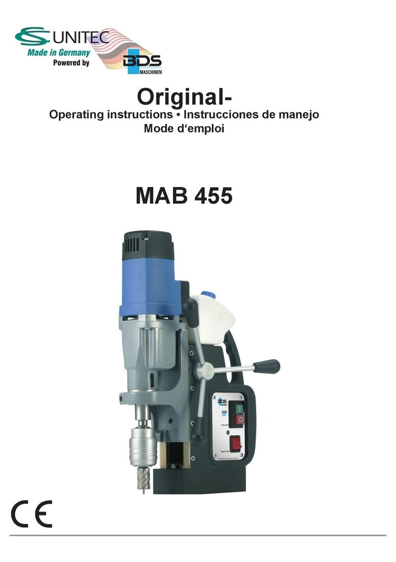
CS Unitec MAB 485 User manual

1
M A B 4 8 5
www.csunitec.com
M A B 4 8 5
O r i g i n a l
O p e r a t i n g i n s t r u c t i o n s • In s t r u c c i o n e s d e m a n e j o
M o d e d ‘ e m p l o i

2
M A B 4 8 5
C o n t e n t s P a g e
O p e r a t i n g i n s t r u c t i o n s .............. 4
So m m a i r e P a g e
M o d e d ’ e m p l o i ................... 6 5
In d i c e P á g i n a
In s t r u c c i o n e s d e m a n e j o ........... 3 4
2 2 Ha r b o r A v e n u e , No r w a l k , C T 0 6 8 5 0 U SA
T o l l - F r e e : 8 0 0 - 7 0 0 - 5 9 1 9
Phone:203-853-9522
Fax:203-853-9921
Em a i l : i n f o @ c s u n i t e c . c o m
w w w . c s u n i t e c . c o m
Distributed exclusively by:
BA_MAB485_1109_A3 © 2012 BDS Maschinen GmbH

3
M A B 4 8 5
ENGLISH
www.csunitec.com
T a b l e o f C o n t e n t s
F o r e w o r d ......................... 4
In s t r u c t i o n s f o r u s e ................ 4
Copyright .........................4
Structure of the safety warnings........5
Intended use.......................6
Liability disclaimer ..................6
Sa f e t y ............................ 7
Fundamental safety precautions .......7
Electric shock hazard ................8
Risk of injury.......................9
Prevention of damage ..............10
Safety installations .................11
Personal protective equipment........12
C o m p o n e n t s / s c o p e o f s u p p l y ....... 1 3
Machine overview..................13
Delivery contents ..................14
Control panel .....................14
Before using for the rst time ....... 1 5
Transport inspection................15
P r e p a r a t i o n s ..................... 1 5
Additional safety measures for
certain operations..................15
Check the condition of the substrate ...16
Inserting the tool...................17
O p e r a t i o n ....................... 2 1
Activating/deactivating magnetic clamp
. .21
Switching machine ON/OFF..........21
Selecting the speed range ...........22
Setting the speed ..................22
Drilling with the machine ............23
Thread cutting ....................25
Reaming/counter-sinking ............25
El i m i n a t i n g b l o c k a g e s ............. 2 6
C l e a n i n g ........................ 2 7
After every use ....................27
M a i n t e n a n c e ..................... 2 8
Adjusting the guide of the machine slide
. .28
Replacing the carbon brushes ........28
After-Sales Service/Service ..........28
T r o u b l e s h o o t i n g .................. 2 9
Faults - causes and remedies ........29
St o r a g e / d i s p o s a l ................. 3 0
Storage..........................30
Disposal .........................30
A n n e x .......................... 3 1
Technical data ....................31
EC Declaration of Conformity.........32

4
F o r e w o r d
M A B 4 8 5
ENGLISH
www.csunitec.com
F o r e w o r d
With the purchase of this machine you have decided in favor of
a quality product whose engineering and sturdiness have been
designed to meet the high demands of day-to-day professional
use.
Read all the information contained here to familiarize yourself
quickly with the machine and to be able to make full use of its
functions.
This machine will serve you for many years to come if you handle
and treat it properly.
In s t r u c t i o n s f o r u s e
These operating instructions form an integral part of the
Magnetic Core Drilling Machine MAB 485 (hereinafter referred
to as "machine") and contains important information for the
commissioning, safety, intended use and care of the machine.
The operating instructions must be kept near the machine at all
times. They must be read and observed by all persons entrusted
with operation, troubleshooting and/or cleaning of the machine.
Keep these operating instructions in a safe place and pass them
on with the machine to any future owners.
C o p y r i g h t
This document is protected by copyright.
Any duplication or reprinting, in whole or in part, and the
reproduction of the illustrations even in modied form is only
permitted with the written approval of the manufacturer.

5
In s t r u c t i o n s f o r u s e
M A B 4 8 5
ENGLISH
www.csunitec.com
St r u c t u r e o f t h e s a f e t y w a r n i n g s
The following warnings are used in the present operating
instructions:
D A NGER
A w a r n i n g o f t h i s c a t e g o r y d r a w s a t t e n t i o n t o a n i m p e n d i n g
d a n g e r o u s s i t u a t i o n .
If the dangerous situation is not avoided, it may lead to serious
injury or even death.
►Follow the instructions in this warning to avoid the danger of
serious injury or even death.
W A R NING
A w a r n i n g o f t h i s c a t e g o r y d r a w s a t t e n t i o n t o a p o t e n t i a l l y
d a n g e r o u s s i t u a t i o n .
If the dangerous situation is not avoided, it may lead to injuries.
►Follow the instructions in this warning to avoid the risk of
injury.
CAUTION
A w a r n i n g o f t h i s c a t e g o r y d r a w s a t t e n t i o n t o p o t e n t i a l
m a t e r i a l d a m a g e .
If the situation is not avoided, it may lead to material damage.
►Follow the instructions in this warning to avoid material
damage.
NOTE
►A note draws attention to additional information that simpli-
es the use of the machine.

6
In s t r u c t i o n s f o r u s e
M A B 4 8 5
ENGLISH
www.csunitec.com
In t e n d e d u s e
The machine is intended solely for drilling operations in magnetic
and non-magnetic metals, and for cutting threads, countersinking
and reaming within the limits specied in the technical data.
Use in any other or further way is not considered an intended use.
W A R NING
D a n g e r f r o m u s e f o r o t h e r t h a n t h e i n t e n d e d p u r p o s e !
If not used for its intended purpose and/or used in any other
way, the machine may be or become a source of danger.
►Use the machine only for its intended purpose.
►Observe the procedures described in these operating
instructions.
No claims of any kind will be accepted for damage or injury
resulting from use of the machine for other than its intended
purpose.
The risk has to be borne solely by the machine owner.
NOTE
►If used commercially, pay attention to compliance with the
accident prevention regulations and the Safety at Work
Ordinance.
Li a b i l i t y d i s c l a i m e r
All technical information, data and instructions for commissioning,
operation and care of the machine contained in these operating
instructions represent the latest status at the time of printing.
The manufacturer assumes no liability for damage or injury
resulting from failure to observe the operating instructions, use
for other than the intended purpose, unprofessional repairs,
unauthorised modications or use of non-approved spare parts
and accessories, tools and lubricants.

7
Sa f e t y
M A B 4 8 5
ENGLISH
www.csunitec.com
Sa f e t y
C A U T IO N
W h e n u s i n g e l e c t r i c a l t o o l s , t h e f o l l o w i n g f u n d a m e n t a l
p r e c a u t i o n s m u s t b e t a k e n t o p r o t e c t a g a i n s t e l e c t r i c s h o c k
and the risk of injury and re!
F u n d a m e n t a l s a f e t y p r e c a u t i o n s
■Do not use the machine in ammable or potentially explosive
environments.
■Persons who due to their physical, mental or motor response
abilities are unable to operate the machine safely may
only use the machine under supervision or instruction by a
responsible person.
■Persons with heart pacemakers or other medical implants
must not use this machine.
■Children must not be allowed to use the machine.
■Inspect the machine for visible signs of damage before use.
Do not use a visibly damaged machine.
■Before beginning work, check the condition of the safety chain
and the function of the switches on the machine.
■Repairs to the mains cable may only be carried out by a
qualied electrician.
■Repairs to the machine may only be carried out by an
authorised workshop or by the works after-sales service.
Unqualied repairs can lead to considerable danger for the
user.
■Repairs to the machine during the warranty period may
only be carried out by a service centre authorised by the
manufacturer, as otherwise the warranty will be voided.
■Defective parts may only be replaced with original spare parts.
Only these parts guarantee that the safety requirements are
satised.

8
Sa f e t y
M A B 4 8 5
ENGLISH
www.csunitec.com
■Do not leave the machine unsupervised during operation.
■Store the machine in a dry, temperate location out of the reach
of children.
■Do not leave the machine standing outdoors and do not
expose it to moisture.
■Make sure that your work area is sufciently lit (>300 Lux).
■Do not use low power machines for heavy working.
■Make sure that your workplace is clean.
■Keep the machine clean, dry and free of oil and grease.
■Follow the instructions on lubricating and cooling the tool.
El e c t r i c s h o c k h a za r d
D A NGER
D a n g e r t o l i f e b y e l e c t r i c s h o c k !
C o n t a c t w i t h l i v e w i r e s o r c o m p o n e n t s c o u l d l e a d t o s e r i -
o u s i n j u r y o r e v e n d e a t h !
Observe the following safety precautions to avoid electric
shocks:
►Do not open the housing of the machine. Risk of electric
shock if live terminals are touched.
►Never immerse the machine or the plug into water or other
liquids.
►Use only extension leads or cable drums with a cable cross-
section of 1.5 mm².
►Only use extension leads that are approved for the place of
work.
►Check the condition of the extension lead regularly and
replace if damaged.
►Avoid direct body contact with grounded parts (e.g., tubes,
radiators, steel girders) to reduce the risk of electric shock in
the event of a defect.

9
Sa f e t y
M A B 4 8 5
ENGLISH
www.csunitec.com
R i s k o f i n j u r y
W A R NING
Im p r o p e r h a n d l i n g o f t h e m a c h i n e i n c r e a s e s t h e r i s k o f
i n j u r y !
Observe the following safety precautions to avoid injuring your-
self and/or others:
►Operate the machine only with the protective equipment
stipulated in these operating instructions (see section
Personal protective equipment).
►Do not wear protective gloves when the machine is running.
A glove can be caught by the drilling machine and torn off
the hand. Risk of losing one or more ngers.
►Remove loose jewellery before beginning work. Wear a hair
net if you have long hair.
►Always switch off the machine before changing tools,
performing maintenance or cleaning. Wait until the machine
has come to a complete standstill.
►Always remove the plug from the mains socket before
changing tools, cleaning or performing maintenance, in
order to avoid unintentional starting of the machine.
►Do not put your hand into the machine while it is in
operation. Remove shavings only when the machine is at a
standstill. Wear protective gloves when removing swarf.
►When working on scaffolding, the operator must be secured
with a safety belt as the machine can oscillate dangerously
in the event of interruption to the power supply.
►Check for secure clamping of the electromagnets on the
substrate before every use (see section Preparing).
►Secure the machine with the safety chain supplied when
working from an inclined or vertical position or during
overhead work. The machine could fall down if the magnet is
loosened or the power fails.
►Check that the tool is tightened securely before using (see
section Inserting the tool).
►Do not allow the connecting cable to hang over edges
(danger of tripping).

1 0
Sa f e t y
M A B 4 8 5
ENGLISH
www.csunitec.com
P r e v e n t i o n o f d a m a g e
CAUTION
P o t e n t i a l p r o p e r t y d a m a g e i n c a s e o f i n e x p e r t h a n d l i n g o f
t h e m a c h i n e !
Observe the following instructions to avoid property damage:
►Before connecting the machine, compare the connection
data (voltage and frequency) on the rating plate with those
of your mains power supply. The data must correspond in
order to avoid damage to the machine.
►Always carry the machine at the handle, not by the
connecting lead.
►Always pull the mains lead out of the plug socket at the plug,
not at the mains lead.
►Do not pinch the connecting lead.
►Do not expose the connecting lead to heat or chemical
liquids.
►Do not pull the connecting lead across sharp edges or hot
surfaces.
►Lay the connecting lead in such a way that it cannot be
caught and wound up in the rotating part of the machine.

1 1
Sa f e t y
M A B 4 8 5
ENGLISH
www.csunitec.com
Sa f e t y i n s t a l l a t i o n s
R e s t a r t i n g p r o t e c t i o n
NOTE
►The machine stops automatically of the magnetic clamp is
switched off or in the event of a power failure.
In order to prevent unexpected starting of the machine when the
magnetic clamp is switched on again or when the power supply
returns after a power failure ("restarting protection"), the machine
must be switched on at the ON/OFF switch again.
M a g n e t i n d i c a t o r
The magnet indicator provides a visual control of the magnet's
clamping force.
■Magnet indicator is lit GR EEN:
The magnet's clamping force satises the minimum
requirements. Machining can be carried out.
■Magnet indicator is lit RED:
Insufcient magnet clamping force. Machining must not be
carried out with the machine. This can be the case in the event
of insufcient material thickness, uneven surface or due to
paint, scale or zinc coatings.
T h e r m a l o v e r l o a d p r o t e c t i o n
The machine is additionally equipped with thermal overload
protection. If the machine becomes too hot, it switches off
automatically.
Carry out the following steps before continuing to work with the
machine:
Remove any blockages that may have occurred.
Allow the machine to run at no-load speed for approx. 2
minutes.
The machine is then ready for operation again.

1 2
Sa f e t y
M A B 4 8 5
ENGLISH
www.csunitec.com
Sy m b o l s o n t h e m a c h i n e
The symbols on the machine have the following meaning:
Sy m b o l M e a n i n g
Electric shock hazard!
Read the operating instructions before beginning
work!
Wear protective goggles and ear protection!
P e r s o n a l p r o t e c t i v e e q u i p m e n t
Wear the following protective equipment at all times when working
with the machine:
Sy m b o l M e a n i n g
Close-tting work protection clothing with a low tear-
ing resistance
Goggles for protecting eyes against ying parts and
liquids and ear protection in areas with noise emission
>80 dB(A)
Safety shoes to protect the feet from falling objects
Wear the following additional protective equipment during special
operations:
Sy m b o l M e a n i n g
Helmet to protect your head from falling objects
Wear a safety belt where there is a danger of falling
Working gloves as protection against injury

1 3
C o m p o n e n t s / s c o p e o f s u p p l y
M A B 4 8 5
ENGLISH
www.csunitec.com
C o m p o n e n t s / s c o p e o f s u p p l y
M a c h i n e o v e r v i e w
1 2
1 0
9
87
6
5
3
1 4 1 3
4
2
1 1
1
1 Core drill (not supplied as standard) 8 Filler neck for cutting oil
2 KEYLESS quick-change drill chuck
system tool mounting
9 Cutting oil tank
3 Morse taper MK2 10 Handle
4 Opening for ejector pin 11 Hand lever
52-speed gearbox with selector 12 Control panel
6 Drive motor 13 Magnetic foot
7 Electronic speed controller 14 Machine slide and guide

1 4
C o m p o n e n t s / s c o p e o f s u p p l y
M A B 4 8 5
ENGLISH
www.csunitec.com
D e l i v e r y c o n t e n t s
A B , C D E F G H
MAB 485 machine (not illustrated) F Tapered mandrel MK2/B16
A KEYLESS quick-change drill chuck
system
G Adapter for thread taps M10/M12/M16
H Key-type drill chuck
B Ejector pin ZAK 075 Operating instructions/guarantee card
(not illustrated)
C Ejector pin ZAK 100
D Safety chain Transport case
(not illustrated)
E Ejector pin MK2
C o n t r o l p a n e l
2 1
2 2
2 4
2 3
21 Motor ON/OFF switch
22 Magnet ON/OFF switch
23 Direction of rotation switch
24 Magnet indicator

1 5
Before using for the rst time
M A B 4 8 5
ENGLISH
www.csunitec.com
Before using for the rst time
T r a n s p o r t i n s p e c t i o n
The machine is supplied as standard with the components
indicated in chapter Components/scope of supply.
NOTE
►Inspect the delivery for completeness and obvious signs of
damage. Report an incomplete or damaged delivery to your
supplier/dealer immediately.
P r e p a r a t i o n s
This chapter contains important instructions for the necessary
preparations before starting work.
A d d i t i o n a l s a f e t y m e a s u r e s f o r c e r t a i n o p e r a t i o n s
Additional safety precautions must be taken for the following
operations with the machine:
No n - h o r i zo n t a l w o r k i n g p o s i t i o n
W A R NING
R i s k o f i n j u r y f r o m t h e f a l l i n g m a c h i n e .
When working in inclined or vertical position and during
overhead work, the machine must be secured to prevent it from
falling using the safety chain (D) supplied.
►Check the safety chain for proper function before every
use. A damaged safety chain must not be used. Replace a
damaged safety chain immediately.
►Attach the safety chain in such a way that the machine
moves away from the operator in the event of slipping.
►Lay the safety chain as tightly as possible around the handle
of the machine.
►Check the secure tting of the safety chain and lock before
starting work.
►Use the protective equipment stipulated in chapter Personal
protective equipment.

1 6
P r e p a r a t i o n s
M A B 4 8 5
ENGLISH
www.csunitec.com
W o r k o n s c a f f o l d i n g
W A R NING
R i s k o f f a l l i n g f r o m s u d d e n o s c i l l a t i n g m o v e m e n t s o f t h e
m a c h i n e .
When working on scaffolding, the machine can make a sudden
oscillating movement on starting or in the event of a power
failure.
►Secure the machine with the safety chain (D) supplied.
►Wear a safety belt to protect yourself from falling.
C h e c k t h e c o n d i t i o n o f t h e s u b s t r a t e
The magnet clamping force is dependent on the condition of the
substrate. The clamping force is signicantly reduced by paint,
zinc and scale coatings and rust.
The substrate must satisfy the following preconditions in order
that a sufcient magnet clamping force can be achieved:
■The substrate must be magnetic.
■The clamping surface and the magnetic foot must be clean
and grease-free.
■The clamping surface must be completely smooth and level.
NOTE
►Clean the substrate and the magnetic foot of the machine
before use.
►Remove any unevenness and loose rust from the substrate.
►CS Unitec offers special holding devices in its range of
accessories.
The best clamping effect is obtained on low-carbon steel substrate
with a thickness of at least 3/4" (20 mm).

1 7
P r e p a r a t i o n s
M A B 4 8 5
ENGLISH
www.csunitec.com
St e e l o f l o w t h i c k n e s s
When drilling in steel of low thickness, an additional steel plate
(minimum dimensions 4" x 7-7/8" x 3/4" [100 x 200 x 20 mm])
must be placed under the workpiece. Secure the steel plate to
prevent it from falling.
NF m e t a l s o r w o r k p i e c e s w i t h a n u n e v e n s u r f a c e
A special holding device must be used when drilling in NF metals
or in workpieces with an uneven surface.
NOTE
►CS Unitec offers special clamping devices for tubes and
non-magnetic materials in its range of accessories.
In s e r t i n g t h e t o o l
The machine is equipped with an MK tool mounting. Depending
on the type of tool to be used, corresponding drill chucks, quick-
clamping systems or adapters must be employed.
T o o l T o o l m o u n t i n g t o b e u s e d
Tool with
taper MK
Insert the tool directly into the morse taper
(3).
Tools with
19 mm Weldon shank
Use KEYLESS quick-change drill chuck
system (A).
Tools with
straight shank
Use key-type drill chuck (H) with tapered
mandrel MK2/B16 (F).
Thread taps
Use KEYLESS quick-change drill chuck
system (A) with the appropriate adapter
(G) for thread taps.

1 8
P r e p a r a t i o n s
M A B 4 8 5
ENGLISH
www.csunitec.com
Sa f e t y p r e c a u t i o n s
W A R NING
R i s k o f i n j u r y !
►Do not use damaged, soiled or worn tools.
►Carry out tool changes only when the machine is switched
off and at a standstill. Remove plug from the mains socket.
►After inserting, check that the tool is engaged securely.
►Only use tools, adapter and accessories that match the
machine.
M K t o o l m o u n t i n g
In s e r t i n g t h e t o o l
Before mounting, clean the shank of the tool, adapter or drill
chuck and the morse taper (3) of the machine.
Push the tool from below into the morse taper (3) of the
machine.
W A R NING
R i s k o f i n j u r y f r o m i n c o r r e c t l y i n s e r t e d t o o l !
►Check the proper seating of the tool, adapter or drill chuck in
the MK tool mounting.
R e m o v i n g t h e t o o l
Turn the tool until the ejector pin (E) slips into the opening for
the ejector pin (4).
Prise out the tool with the ejector pin (4) or loosen the tool by
tapping against the ejector pin.

1 9
P r e p a r a t i o n s
M A B 4 8 5
ENGLISH
www.csunitec.com
K e y - t y p e d r i l l c h u c k
In s e r t i n g t h e t o o l
Push the key-type drill chuck (H) onto the tapered
mandrel (F) and push the combination into the morse taper
(3) of the machine.
Open the drill chuck and insert the tool into the drill chuck.
Close the drill chuck by hand and then tighten the drill chuck
with the chuck key.
R e m o v i n g t h e t o o l
Unlock the drill chuck with the chuck key and remove the
tool.
W A R NING
R i s k o f i n j u r y !
►Tighten the drill chuck only with the chuck key provided.
►Always remove the chuck key from the drill chuck after
tightening or loosening.

2 0
P r e p a r a t i o n s
M A B 4 8 5
ENGLISH
www.csunitec.com
K EY LESS q u i c k - c h a n g e d r i l l c h u c k s y s t e m
In s e r t i n g t h e t o o l
Push the KEYLESS quick-change drill chuck system (A) into
the morse taper (3) of the machine.
Connect the lubricant line.
Open the quick-change drill chuck system (A) by pushing up
the sleeve and insert the tool into the chuck.
NOTE
►Insert the appropriate ejector pin before inserting the core
drill.
W A R NING
R i s k o f i n j u r y f r o m i n c o r r e c t l y i n s e r t e d t o o l o r t o o l
m ounting.
►Check by briey turning the tool whether the collet is
engaged.
R e m o v i n g t h e t o o l
Open the quick-change drill chuck system (A) by pushing up
the sleeve and pull the tool down out of the chuck.
A d a p t e r f o r t h r e a d t a p s
In s e r t i n g t h e t o o l
Insert the appropriate adapter for thread taps (G) into the
KEYLESS quick-change drill chuck system (A).
Insert the thread tap into the adapter for thread taps (G).
R e m o v i n g t h e t o o l
Pull the thread tap down out of the adapter for thread taps
(G).
Open the quick-change drill chuck system (A) by pushing up
the sleeve and pull the adapter for thread taps (G) down out
of the chuck system.
Table of contents
Languages:
Other CS Unitec Drill manuals
