CSC WIZ User manual


The electric motorcycle can be used on road only.
The user should read this manual carefully. You should have a proper command of basic operation
of this scooter. The data, technical specifications and performance parameters labeled in the
manual are compiled based on the latest status. We reserve the right to amend the manual at any
time without separate notice.
You may not reproduce any part of the manual without our written approval. Please us your
opinions on this product. If you have any recommendations, please let us know.
For more information, please contact us.
Used batteries should be recycled at appropriate sites.
Only use genuine CSC components and accessories on this product.
CSC Motorcycles
1331 Foothill Boulevard
Azusa, California 91730
909 445 0900
www.CSCMotorcycles.com
1

!
!
!
!
1. Always wear protecve gear.
2. It is forbidden to hang any item on the steering
handle bar.
3. Please charge the baery using only the origi-
nal charger.
4. Please switch o the air switch and electric lock
when plugging the baery socket.
1. Please check the accessories and all informa-
on with the electric motorcycle aer opening
the box.
2. The maximum payload is 150kg and the trunk’s
payload is 3kg.
3. Do no alter any components.
4. To avoid any damage to the battery, always
fully charge the baery. Do not set the baery
upside down when charging. Do not ush it with
pressurized water.
1. Turn the air switch o when the electric motor-
cycle is idle.
2. Charge the baery at least once a month.
Danger Cauon
Warning Suggeson
1. Observe trac rules ride safely.
2. Do not operate the motorcycle without a li-
cense.
3. Do not operate the vehicle while udner the in-
uence of drugs or alcohol.
2

Contents
Appearance and the Name of Components.............................................................................................. 4
Engine start lock, USB, Manipulation handle ............................................................................................ 5
Instrument Indicators................................................................................................................................ 6
LHS and RHS switches................................................................................................................................ 7
Items to Be Checked before Operation .................................................................................................... 8
Starting and Operation ............................................................................................................................. 9
Inspection and Adjustment after Break-in ................................................................................................ 10
Regular Maintenance ............................................................................................................................... 11
Maintenance Requirements...................................................................................................................... 12
Maintenance of Air Switch ....................................................................................................................... 12
Charger Use and Maintenance of Charger ............................................................................................... 1 3
Battery Use and Maintenance .................................................................................................................. 14
Lithium Battery Removal........................................................................................................................... 1 5
Drive Motor Maintenance......................................................................................................................... 1 6
Wheel and Tire Inspection ........................................................................................................................ 1 6
Brake Inspection and Adjustment ............................................................................................................ 17
Cleaning and Storage ................................................................................................................................ 18
Specifications ............................................................................................................................................ 19
Electrical Schematic................................................................................................................................... 20
3

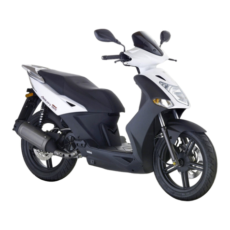
Appearance and the name of components
1. Headlamp 2. Instrument 3. Document box 4. Charging interface 5. Seat 6. Trunk 7. Tail lamp
8. Front wheel 9. Front shock absorber 10. Front pedal 11. Side stand 12. Rear wheel
1
3
8
9
7
2
5
6
10
11
12
4
4

No. Name Description of functions
1
Power source On
Turn the key to the posion to enable starng
2
Power source O
Turn the key to the posion to disable starng
3 Steering lock Turn the key to the posion to lock the steering han-
dle and the electric motorcycle is not available
4USB interface Connect the mobile phone charging wire for charging
5Speed regulaon
handlebar
Turn the speed regulation handlebar to control the
speed.
6 Front brake handle Control the speed of the front wheel of which the free
travel is 10mm-20mm
7 Rear brake handle Control the speed of the rear wheel of which the free
travel is 10mm-20mm
Engine start lock, USB, manipulation handle
Warning
1. Park the motorcycle in a safe place and lock the steering to prevent it from being stolen.
2. Adjust and maintain the motorcycle properly on a regular basis.
4
1
2
3
56
7
5

No. Name Description of function
1LHS turn signal lamp LHS turn signal lamp “ ” flickers when
it is being used.
2Coulombmeter
It indicates the current electric quan-
tity. It means lower electric quantity
when the pointer stands at the red
line. Please charge as soon as possi-
ble.
3Odometer
It indicates the mileage covered. The
mileage over a single trip is to be
zeroed when the key is turned off.
4 Display of current It displays the present current of the
controller.
Instrument indicators
15
2 3 4
6
8
7
9
10
11
12
6
No. Name Description of function
5RHS turn signal
lamp
RHS turn signal lamp “ ”flickers when
it is being used
6High beam
indicator
High beam indicator is illuminated
when it is being used
7Display of
temperature
It displays the present temperature of
the instrument circuit board.
8Photosensitive
sensor
Headlamp switch is being off. When
ambient light is much too dim,
photosensitive sensor switches on the
headlamp automatically.
9Speedometer km/h It indicates the speed at which the
motorcycle is running.
10 Readiness lamp
being illuminated when there is no
trouble found throughself-detection,
vice versa.
11 Display of gear It displays the present gear at which
the motorcycle is running.
READY

No. Name Description of function
6Lighng switch Operates lights.
8 Mode switch Dependng on different circumstances, allows switching to different operating modes for
power output and battery life.
7 Cruise control can be enabled with this switch.
9 Emergency switch Both LHS and RHS turn signal lamps flash by pressing the button
No. Name Description of function
1High-low beam
switching buon
High beam lamp is illuminated when the lighting
switch is turned to“ ”.Low beam is illuminated
when the lighng switch is turned“ ”
2Horn buon Press and hold the buon when there is a need to trum-
pet.
3
Turn both LHS and RHS turn signal lamps buon swith;
LHS turn signal lamp or RHS one ickering if driving direc-
on needs to be changed
4 Restoring key
When the electric circuit for handle bar is faulty
or there is motor hall default phase, the complete
motorcycle is under the state of braking. This
button enables low- speed operating
LHS and RHS switches
1
2
4
6
78
9
3
7
Turn signal switch
Cruise control

Items to be checked before operation
Check the items before operaon to ensure the user can drive smoothly and safely
8
No. Item Check Remarks
1Baery Check if the power of battery is sufficient
2 Driveline Check if the controller and driving motor can work as
intended
3 Brake liquid Check if the brake fluid has deteriorated and if the level
of brake fluid stands below the lower-end scale
4 Brake handle Check if the free travel is within the specified value or
not
5 Shock absorber Check if the shock absorber works
6 Speed governing handlebar Check if speed governing handlebar is flexible
7 Steering gear Check if the steering is free and stable
8 Tire/wheel Check the tire for tire pressure and wear
9Lighng/signal indicator Check if lighting lamps/signal lamp/indicators work as
usual
10 Brake Check the brake show for wear and any problem with
braking performance
11 Main stand/side stand Check if the main stand/side stand has been distorted
or not and check them for improper return
12 All fastener Check all the fasteners for loose connection and any
parts falling off
Maintain the motorcycle as
specified in this manual.

Starting and Operation
2
3
4
Note
6
5
1. Insert the key into the seat lock hole to open the seat and
turn air switch to “ON” to enable the general power source.
2. Insert the key into power source lock and turn it to
the on position.
3. Grip the front & rear brake handle to prevent the
motorcycle rolling away.
4. Please switch on the turn signal indicator to win the
attention of pedestrians and vehicles.
5. Retract the side stand to deactivate the protective state
of controller.
6. Loosen both front & rear brake handles. Turn the RHS
speed governing handlebar with right hand in order to
move the motorcycle.
1. The controller is under power-o protecve state when the side support is deployed and the motorcycle is parked. At
this moment, it is forbidden to ride the motorcycle in order to keep the motorcycle dashing forward as a result of driv-
er’s unintended rotaon of the handlebar.
2. The driver and the passenger should wear helmets, protecve gloves, and other protecve wear prior to operaon.
1
9

The user shall aach importance to run-in aer purchasing a new motorcycle. The inial mileage of
600 miles is the break-in period.
The performance of break-in has direct impact on the service life. Break-in refers to a process during
which all components can beer t in well with each other and deliver beer performance aer having
used the new motorcycle over period of me. At the end of the break-in period, an overall adjustment
shall be applied to the motorcycle so as to ensure it can work as usual and also can deliver beer re-
sponse and durability. The adjusng items are shown as follows:
1. Adjusng bearing
Over the course of break-in, the steel ball, axle-bowl and the rollaway nest surface between axle
bumpers tend to be smoother and t to a greater extent under load. However, the clearance shall be ad-
justed appropriately.
2. Adjustment of braking system
All components of the braking system are t beer for each other over a certain period of use.
Brake components tend to be t beer aer break-in. For safe operaon, free travel of braking system
shall be adjusted appropriately.
3. Adjustment of fasteners
Bolts and nuts tend to loosen during break-in. Therefore, it is necessary to inspect and maintain to
ensure the motorcycle will work as intended.
Inspection and adjustment after break-in
10

Regular Maintenance
11
Reading on odometer
300 Miles 2000 Miles 4000 Miles 8000 Miles Remark
Controller Check Check Check
The maintenance
period shall be
shorter for riding
in an area with
unusual moisture
or heavy dust.
Air switch Check Check Check
Manipulation Cleaning Cleaning Cleaning Cleaning
Braking handle Adjustment Adjustment Adjustment Adjustment
Battery The user charges based on mileage covered
Braking shoe Check Check Check Replacement
Brake Adjustment Check Adjustment Adjustment
Indicator bulb Check Check Check Check
Lighting bulb Check Check Check Check
Shock absorber Check Check/lubricating Check/add
lubricating
Check/add
lubricating
Fastener Fastening Fastening Fastening Fastening
Front/rear inner
and outer tube Check Check Check Replacement
Steering gear
bearing Check Check Check Check
Braking cable Check/lubricating Add lubricating
grease
Replace lubricating
grease Check/lubricating
Front/rear wheel
bearing Check/lubricating Check/lubricating Check/lubricating Check/lubricating
Motor Check/lubricating Check/lubricating Check/lubricating Check/lubricating
Miles
Items

Note:
it is necessary to switch o the air switch when motorcycle is not being used. By doing so, the full charge can be maintained
resulng in longer baery service life.
Maintenance of air switch
The output end of baery is in serial connecon with the air switch. In case charging
current or discharging current is higher than the specied value, fuse may be disconnected
automacally to protect baery and electrical components from damage. Turn the switch to
“ON” posion to energize the complete motorcycle and to “OFF” posion to disconnect power
source. The power source switch has to be connected at charging. First check if air switch is on
“No” or not if the motorcycle is not energized. If so, turn it to “ON”posion.
Maintenance requirements
Components may loosen and wear during operation. It is necessary to maintain the motorcycle on a regular basis in
order to extend its service life, lower repair costs and achieve safe operation.
1. Keep the motorcycle clean, fully charged, and free from rattles.
2. Keep all connections and fasteners secure. Keep all lubricating points fully lubricated.
3. Ensure it is easy to operate front/rear brake handles.
4. Ensure the front/rear shock absorbers work in a steady and reliable manner.
5. Ensure the tire pressure is normal.
6. Ensure all parts for power supply, electrical system and control system work as usual.
7. Ensure the battery connection is reliable and secure as well as is free of wear or rust.
12

The charger is an important part of the motorcycle. The performance of the charger can heavily affect the service life of
the battery. A charger mainly consists of a rectifier filter, a high-voltage switch, voltage commutation, control of constant
voltage and charging and others. The charger offers trickle charge. The duration of charging each time shall usually
be shorter than 12 hours. The charger shall be dry and ventilated at charging. Source of flame shall be away from the
battery at charging; the charger shall not be covered by anything in order to avoid fire. The output plug of the charger
shall be connected to the socket on the battery box at charging. Then, the charger plug is inserted into a common power
source socket. At end of charging, the charger’s power source shall be disconnected first before plugging the output
plug out of the battery socket. Keep the charger in a proper manner or place it into the glove compartment.
Warning
1. The charger should be used and stored in a dry environment. Do not drop it or otherwise abuse it.
2. Do not touch the charger while charging. High voltage and current are present.
3. The charger gets hot during charging. Charging shall be conducted at a well-ventilated place. Keep the charger away
from blanket, wooden board and other flammable, explosive items so as to avoid potential fire or explosion accident.
4. The voltage and current of the battery shall be line with the specification of the charger at charging. Meanwhile,
charger’s output plug polarity shall be in line with that of the battery group. Otherwise, this may damage the charger
and battery.
5. As the charger’s indicator does not turn in color over a given period of time or longer than 8 hours, indicator has
been showing red constantly. The charging shall be stopped immediately. Send the charger to a service station for
inspection.
6. Do not attempt to repair or modify the charger.
13
Charger use and maintenance

The battery used on this model is installed below the glove compartment. Small amounts of gas are exhausted at
charging. No acid mist is exhausted under normal conditions. The batter features large capacity, slight amount of
self-discharging, high energy, long service life, reliable safety. It is an ideal power-type baery. Please read the use in-
strucon of the baery carefully prior to the use of the baery.
1. Lithium baery for a new motorcycle features a default electric charge at 40~60%. If it remains within a short period
aer delivery, the user can use the baery on the motorcycle directly. If there is a long period aer delivery (longer than
2 months), the user should charge the baery prior to the use of it. The charger’s green indicator is illuminated 7 to 8
hours aer charging, which indicates the baery has almost a full charge. The charging comes to an end for another 1
to 2 hour-long oang charge.
2. The advanced fully-enclosed energy-saving design is applied to the baery to set the baery free from maintenance,
safe and environmental friendly. Compared to a tradional baery, the baery features a noceably longer service life
and longer full charge endurance.
3. The baery shall not be placed inside the enclosed container and not close to the open ame. Do not throw it into
the re or soak it in the water. It is forbidden to expose it to sun light.
4. In case baery housing is found to be cracked and leaked, install a new baery.
5. The electric quanty of the baery shall be inspected on at a given me every week when the motorcycle is available
for operang. The baery shall be charged mely to avoid shortened service life as a result of lack of electricity.
14
Baery use and maintenance
Note
1. The baery should be stored where it is dry and cool. Keep it upright and from being pressed by heavy items.
2. The ambient temperature shall stand between 0 degrees and 35 degrees at charging. There should be good venlaon. The
lower temperature would aect the charging eciency. The high temperature can lead to change of parameters of the charger
and even to loss of control and swelling of baery.
3. Contact CSC Motorcycles for instrucons on disposal of the baery when it is nececssary to do so.

Removal steps:
1.Turn on the electric lock
2.Open the seat
3.Turn o the air switch
4.Open the baery pressing plate
5.Plug out the charging plug
6.Plug out the discharging plut
7.Li the baery
The installation steps are the reverse of the removal steps.
Lithium baery removal
Note:
before removing the battery, the electric lock and air switch shall be turned off to disconnect the source of
power and to avoid potential danger.
1
4
2
5
3
6
15

Wheel and tire inspection
1.Higher re pressure may lead to poor ride comfort. It will also lead to worn components over a shorter period of me.
Lower re pressure may lead to greater road load and increased energy consumpon. It may also lead to a at re as a
result of local delaminang of re.
2. The valve core shall be repaired or replaced if air leakage is found from inner tube valve core. Inner tube shall be
repaired or replaced if air leakage is found from inner tube
3.The inspecon and adjustment of wheels should occur on a regular basis.
Limit for re wear
Limit for wear Front
Rear
2.0mm
3.0mm
Limits for wheel run-out
Limits for wheel run-
out
Axial
Radial
0.8mm aluminum wheel
Drive motor maintenance
The motorcycle employs a brushless DC rear wheel-mounted motor, with an efficiency of higher than 85%. The
motorcycle features excellent gradability, higher speed, low current consumed for operating, long full charge endurance,
outstanding coasting effect and other advantages.
1. A wet driving motor may deteriorate. Remove the motor and drain the water before drying it with a blower or expose
it to the sunlight. And then, detect the resistor of motor and hall sensor. In case of damage, install a new one.
2. Partly-charged battery may lead to shorter full charge endurance and poor performance of driving motor. The battery
should be fully charged whenever it is charged.
16

Inspection of hydraulic brake
1. Check if brake handle’s free travel is within the scope of standard value or not. If the
brake handle’s travel can not be adjusted any more, it indicates that brake worn beyond
service limit value. A new brake shall be installed.
2. Check the level of brake uid reservoir via access hole. When the level stands below the
lower limit, add brake uid to the higher limit. Use only DOT4 or DOT3 brake uid.
Adjustment of drum brake
Brake inspection and adjustment
1. Check if the brake handle’s free travel is within the scope of standard value or not. If the brake handle’s travel can not be
adjusted any more or the pointer on the braking arm goes beyond the basic scale on the brake drum cover, it indicates that
brake shoe has been worn beyond service limit value. A new brake shoe shall be installed.
2. Hold the braking swing arm and turn the adjusng nut clockwise to shorten the brake handle’s free travel. On the contrary,
turn it to extend the free travel. Try repeang the manipulaon for several mes unl the standard value is reached.
3. Hold the stop lamp switch body and turn the adjusng nut for adjusng stop lamp switch. As long as the brake pedal is ap-
plied, the stop lamp is illuminated, which shows the stop lamp switch has been posioned properly.
Note
1. At the end of adjusng brake, sgrip and release the brake handle several mes while rolling to check if the wheel can
spin freely. At the end of adjusng brake, check the rear stop lamp switch and adjust if necessary.
2. Use only CSC components when servicing the brakes.
Standard value of brake handle’s free travel: 10mm - 20mm
17

Cleaning and storage
1. Cleaning
(1). Do not flush the motorcycle with high pressure water so as to avoid potential risk as a result of
wet electrical parts and circuits. (2).Wipe the surface of the motorcycle using a clean cotton cloth or
clean towel. (3). Apply wax to the surface of painted parts and apply anti-rust oil to the chrome-plated
surfaces.
2. Storage
(1). If storage is for longer than 60 days the motorcycle shall be cleaned thoroughly before storing it.
(2). The battery should be removed and stored only when it is fully charged. As all batteries discharge
themselves, service life will be shorter if they are stored partially or fully discharged. The best practice is
to charge the battery once every month. The battery should be stored indoors in a dry area. Do not store
the battery where it overly heated or humid. (3). Remove the manipulative cable and clean and lubricate
it. Store the motorcycle on a pad such that the tires are off the ground. (4).The motorcycle should be
stored where it is ventilated, dry, out of the sunlight, and away from flammable items, chemical items,
corrosive items and other harmful items.(5). The motorcycle shall be cleaned and checked again when
taken out of storage. Switch the power lock on to check the electrical circuit throughout the motorcycle
and charge the battery.
18

Note: Full charge endurance refers to the distance covered when the motorcycle runs over an even road continuously
with fully charged battery and rated loading until controller’s low-voltage protection function is enabled. The full charge
endurance varies depending upon road conditions, number of parking and starting events, level of loading, wind load,
temperature and others factors.
19
Specifications
Dimension L×W×H 1785×655×1240mm
Wheelbase 1285mm
Min. ground clearance 140mm
Curb weight 91kg
Max. payload 150kg
Tire specification/tire pressure Front3.50-10/225kpa Rear3.50-10/250kpa
Max. speed 70km/h
Full charge endurance 20km/h - 140km
Motor type and model
72V/3KW Wheel hub motor (2.15MT×10)
Electric quantity consumed
per 100km ≤3kw.h
Controller 72V 18GSinusoid
Battery type Lithium battery
Battery specification 72V/30Ah
Under-voltage 58±1V
Over-current protection 60±2A
Charger AC220V output current 5A
Table of contents
