CTM CW-24H Instruction Manual

CTM MARINE
CHILLED WATER SYSTEMS
CW MODELS
(24,000 / 36,000 / 48,000 / 60,000 / 72,000 BTU)
AIR HANDLER MODELS
(6,000 / 8,000 / 12,000 / 16,000 / 24,000 BTU)
INSTALLATION & USER MANUAL
CTM-MARINE
www.ctm-marine.com
Please visit http://ctm-marine.com/user-manual/
for the most updated version of this manual. Form No. UM-CW1001123


INDEX
3
HOW TO READ THIS MANUAL .....................................................................................
UNIT LABEL INFORMATION ...........................................................................................
WARNING LABELS ................................................................................................................
PRODUCT DESCRIPTION & FEATURES ..................................................................
BOAT INSTALLATION DIAGRAM .................................................................................
PARTS DIAGRAM CHILLED WATER SYSTEMS ..................................................
PARTS DIAGRAM AIR HANDLER UNITS ...........................................................
TECHNICAL DATA ..................................................................................................................
CHILLED WATER SPEC SHEET .....................................................................................
CHILLED WATER UNIT INSTALLATION ..................................................................
AIR HANDLER SPEC SHEET ...........................................................................................
AIR HANDLER INSTALLATION ......................................................................................
SALTWATER SYSTEMS ........................................................................................................
CHILLED WATER SYSTEMS .............................................................................................
DUCTING SYSTEMS ...............................................................................................................
INSTALLATION DIAGRAM................................................................................................
MARINE CHILLER CONTROL .........................................................................................
ERROR MESSAGES ...............................................................................................................
PROGRAM PARAMETERS ................................................................................................
MCC STAGING CONTROLLER ........................................................................................
MCC STAGING CONTROLLER PROGRAMMING ...............................................
STAGING CONTROLLER FAULT PROTOCOL .......................................................
ADDITIONAL FAULT TROUBLESHOOTING INFORMATION .....................
SPECIFICATIONS .....................................................................................................................
MCC WIRING DIAGRAM .....................................................................................................
MCC STAGING CONTROLLER DIAGRAM ...............................................................
TWO SPEED OPERATION .................................................................................................
NOTES .............................................................................................................................................
COPYRIGHT .................................................................................................................................
4
6
7
8
9
10
11
12
13
14
15
16
18
19
23
24
25
26
27
28
29
32
33
34
36
37
38
39
41
CTM Marine Chilled Water Systems Installation & User Manual

Please read and follow the safety information and instructions carefully before installing your unit.
You can always contact Customer Service if you have any doubts, concerns or questions about the
contents in this instructions manual. Failure to heed these warnings and instructions could not
only result in malfunction of the product, but also result in death serious injury.
CTM Marine does not accept liability for damage in the case of:
> Failure to assemble or connect the unit properly following the instructions in this manual.
> Damage to the unit and its accessories resulting from mechanical influences and excess voltage.
> Any alternation to the units without permission from CTM Marine.
> Use for purposes other than the purposes described in this manual.
In the interest of product improvement, the specifications and design are subject to change without
prior notice.
HOW TO READ THIS MANUAL
This manual provides proper installation information of CTM-Marine Chilled Water Systems.
Improper installation procedures can result in unsatisfactory performance and / or prenature failure
of these a/c units as well as serious injury or death. Before proceeding please read this manual
completely.
Throughout this manual you will find a few signaling symbols. Please take a time to read and
understand what each signaling symbol means:
Used to indicate additional information.
QR Code for access to virtual content such as tutorial videos.
Used to indicate important and useful information.
Used to indicate a dangerous situation where, if not followed
carefully, could result in serious injury or death.
4
CTM Marine Chilled Water Systems Installation & User Manual

UNIT INSTALLATION
EXPLOSION HAZARD
Do not apply flame or steam to a refrigerant
cylinder. If heat is needed to change faster,
partially immerse the cylinder in warm water.
> A cyclinder should never contain more than 80%
of liquid refrigant.
> Add only R-410A to an R-410A cylinder.
It operates at much higher presures than R-22.
Service equipment used with R-410A must be
listed.
>Do not use a cylinder as a platform or roller.
Always store a cylinder in a cool, dry place.
ELECTRICAL SHOCK HAZARD
> Ensure power source is OFF or disconnected at
main panel before opening any electrical boxes.
Failure to comply may cause serious injury or
death.
>It is imperative that the components of this
system are properly grounded to minimize any
electrical shock hazard and / or personal injury.
REFRIGERANT SAFE HANDLING
Because refrigerants are heavier than air, they can
push out oxygen from your lungs or from
enclosed spaces. To avoid death or difficulty
breathing, take the following precautions:
1- You should never sniff a refrigerant
2- No refrigerant should ever be purged into an
enclosed space or room. By law, all refrigerants
must be reclaimed.
3- If you suspect an indoor leak, you must
thoroughly ventilate the area before you begin
work.
4- If you do get contact with liquid refrigerant,
wear gloves and goggles to avoid frostbite or
blindness. If liquid refrigerant does get in your
eyes or on your skin, seek medical attention
immediately.
5- Refrigerant can cause poisonous gas to be
released if it is burned.
6- Always follow EPA regulations.
Read these instructions completely and then plan all connections
which must be made to the unit including ducting, condensate
drain line, seawater inlet and outlet hoses, electrical power
connection, location of control, and seawater pump placement, to
assure easy access for routing and future servicing for both
chilled water and air handler units.
Installation and servicing of this system can be hazardous due to
system pressure and electrical components. When working on this
equipment, always observe precautions described in the literature,
tags and labels attached to the unit. Follow all safety codes.
Wear safety glasses and work gloves and place a fire extinguisher
close to work area.
MOUNTING THE CHILLED WATER SYSTEM AND THE ELECTRICAL BOX
CHILLED WATER SYSTEM ELECTRICAL BOX
Pay attention to signalling symbols
throughout this manual with important
information.
Some sections of this instructions manual have QR
codes that you can easily scan with your Smartphone.
They generally contain tutorial videos following the
instructions in this manual or additional information.
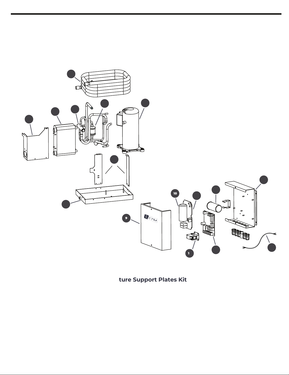
Refer to the illustrations throughout
this manual for guidance.
Some pages have a boxed section on the right to
indicate potential physical injury hazards and
potential damages to the units. It’s important to
read, understand and obey safety instructions.
5
CTM Marine Chilled Water Systems Installation & User Manual
1 - The chiller unit is usually installed in the engine room.
Make sure to install the chiller unit in a horizontal surface strong
enough to hold the unit when the boat is in motion, choose a location
where it will be dry and able to be serviced easily. Allow at least between
3 - 4 feet (0.9 - 1.2m) of space around the unit and at least 3 feet (0.9 m)
above the unit.
2 - The control panel or electrical box which contains all the controls to
operate the chiller should be installed on a dry and flat horizontal or
vertical surface where it could be accessed easily for installation and
servicing. Make sure the location of the control panel is free of water
spray and moisture.

UNIT LABEL INFORMATION
CTMXXXXXX
H = 230 V
HOW TO READ YOUR LABEL
AIR HANDLER UNITS - AH
*Unit Label Data Changes By Model
CHILLED WATER SYSTEMS - CW
6
CTMXXXXXX
25 A / 16 A
24,000 208-240V / 50-60 1
7.6 A / 9.0 A
R410A 28.2 / 800 42 A
500 5/8 / 5/8 3/4 / 3/4 XXXXX 75 LBS
H = 230 V
*Unit Label Data Changes By Model
28 LBS
CTM Marine Chilled Water Systems Installation & User Manual

WARNING
Cancer and reproductive harm
www.P65warnings.ca.gov
R410A
REFRIGERANT
TYPE OF REFRIGERANT
DANGER
ELECTRICAL SHOCK HAZARD
DISCONNECT VOLTAGE AT MAIN PANEL
OR POWER SOURCE INLET BEFORE
OPENING ANY COVER
FAILURE TO COMPLY WILL RESULT IN
INJURY OR DEATH
CAUTION!
HIGH COMPRESSOR
TEMPERATURE IS NORMAL
DO NOT TOUCH
WARNING!
THIS AIR CONDITIONER UNIT, INCLUDING DUCT
WORK, MUST NOT BE INSTALLED IN A FUEL VAPOR
AREA OR ENGINE ROOM WHERE ANY POSSIBILITY
OF FUEL VAPOR, ENGINE EXHAUST OR ANY
OTHER TOXIC GASES MAY EXIST. THIS UNIT IS NOT
VAPOR PROOF AND COULD INTRODUCE DEADLY
GASED INTO THE LIVING SPACE IF IMPROPERLY INSTALLED.
THIS COULD LEAD TO DEATH OR DISABILITY OF THE
OCCUPANTS. SEE OWNER’S MANUAL.
WARNING LABELS
7
CTM Marine Chilled Water Systems Installation & User Manual

Thank you for purchasing our CTM Marine Chiller Systems. The CTM Marine Chiller System is the
best option whenever two or more independent areas need to be air conditioned throughout
the vessel.
The CTM Marine CW chilled water air conditioning system consists of the following:
- The Chiller (CW): The compressor, the condenser, and the evaporator or heat exchanger.
- The Airhandler(s) (AH): The blower and the coil.
- A Freshwater System: Freshwater that circulates through the piping from the chiller to
each airhandler and back.
- A Saltwater System: Seawater circulates through the condenser coil.
When the air conditioner is in cooling mode, the blower draws warm humid cabin air across the
air handler unit (AH). The air transfers to the fresh water circulating through the coil, and the heat
is removed from the air. The now warmed water pumps back to the chiller where it is cooled again
by circulating through the evaporator, and transferring the heat from the water to the refrigerant in
the evaporator coil. The heated refrigerant gas circulates back to the compressor where it is
compressed and circulated through the condenser coil.
The heat from the refrigerant gas is then exchanged to the seawater and discharged overboard.
The chilled freshwater then circulates back to the airhandlers through the freshwater pipe system
in a continuous loop repeating the cycle again. The same process occurs for reverse-cycle heating,
but backwards. The refrigerant flows in the opposite direction through the reversing valve and heat
is transferred from the freshwater system which circulates back to the airhandlers.
CTM Marine Chilled Water Systems Installation & User Manual
8
PRODUCT DESCRIPTION & FEATURES

9
DIAGRAM 1
BASIC CHILLED WATER A/C SYSTEM LAYOUT
IN A MID SIZE BOAT
CTM Marine Chilled Water Systems Installation & User Manual

10
PARTS DIAGRAM
CTM Marine Chilled Water Systems Installation & User Manual
CW - CHILLED WATER SYSTEMS
1
2
5
6
7
8
9
10
12
11
14
3
13 16
1. Heat Exchanger Cover
2. Heat Exchanger
3. Reversing Valve
4. Dryer
5. Condensing Coil
6. Compressor
7. Structure Support Plates Kit
8. Drain Pan
9. Electrical Box Front Cover
10. Soft Start Capacitor
11. Soft Start Control Board
12. Solenoid / Contactor
13. DDC Control Board
14. Start / Run Capacitor
15. Electrical Box Back Plate
16. Electrical Harness
4
15
DIAGRAM 2

11
CTM Marine Chilled Water Systems Installation & User Manual
PARTS DIAGRAM
AH - AIR HANDLER(S)
1
2
3
4
5
6
7
8
11 12
9
10
1. Mounting Duct Ring
2. Blower / Fan
3. Blower / Fan Plate Kit
4. Flow Control Valve
5. Evaporator Coil
13
6. Air Filter
7. Base Frame
8. Drain Pan
9. Electrical Box Front Cover
10. Control Board
11. Compressor Relay
12. Electrical Box Back Plate
13. Electrical Harness
DIAGRAM 3

12
TECHNICAL DATA
CHILLED WATER SYSTEMS
AIR HANDLER UNIT
1. Blower Fan
2. Duct Ring
3. Condensate Drain
4. Base Drain Pan
5. Air Filter
6. Air Handler
7. Circulating Water Outlet
8. Circulating Water Inlet
1
3
4
6
5
2
4
2
6
1
7
5
3
8
7
8
CTM Marine Chilled Water Systems Installation & User Manual
1- Condensing Coil
2- Compressor
3- Heat Exchanger
4- Circulating Inlet
5- Circulating Outlet
6- Drain Pan
7- Reversing Valve
8- Structure Support Plate

Model No. CW-24H CW-36HS CW-48HS CW-60HS CW-72HS
Capacity (BTU)
Voltage (V)
Cycle (Hz) / Phase (Ph)
Input: Cool (A)
Input: Heat (A)
Fuse Max / Mix (A)
Locked Rotator Amps (A)
Suggested Water Flow
(GAL / H)
Water In / Out
Chill Water In / Out
Refrigerant Type
Net Weight (Ilb/kg)
Width (W) in / mm
Height (H) in / mm
Depth (D) in / mm
24,000 BTU’S 36,000 BTU’S 48,000 BTU’S 60,000 BTU’S 72,000 BTU’S
208 - 240 V
50 - 60HZ / 1Ph 50 / 60HZ / 1Ph 50 / 60HZ / 1Ph
CW-24H CW-36HS CW-48HS CW-60HS CW-72HS
13
7.6A / 9A
25A / 16A
7.6A / 9A
75 LBS
42 A
500
5/8” / 5/8”
3/4 “ / 3/4”
R410A R410AR410A
R410AR410A
208 - 240 V
5/8” / 5/8”
750
3/4 “ / 3/4”
35A / 20A
9.5A / 13A
9.5A / 13A
42 A
97 LBS 150 LBS
1.0“ / 1.0”
1500
14A / 19A
14A / 19A
3/4 “ / 3/4”
1000
42 A 42 A
65A / 40A
208 - 240 V
50 / 60HZ / 1Ph 50 / 60HZ / 1Ph
20A / 25A
20A / 25A
161 LBS 167 LBS
208 - 240 V 208 - 240 V
3/4 “ / 3/4”
1.0“ / 1.0”
1250
80A / 50A 90A / 60A
42 A
3/4 “ / 3/4”
1.0“ / 1.0”
23A / 30A
23A / 30A
18.9” / 480 mm
14.1” / 360 mm
9.8” / 250 mm
20” / 510 mm
14.1” / 360 mm
9.8” / 250 mm
19.6” / 500 mm
17.7” / 450 mm
13” / 332 mm
21” / 535 mm
20.2” / 515 mm
13” / 332 mm
20.2” / 515 mm
13” / 332 mm
21” / 535 mm
H
W
W
W
CHILLED WATER SPEC SHEET
WW
H
H
H
H
CTM Marine Chilled Water Systems Installation & User Manual

CHILLED WATER SYSTEM UNIT INSTALLATION
EXPLOSION HAZARD
Do not apply flame or steam to a refrigerant cylinder.
If heat is needed to change faster, partially immerse
the cylinder in warm water.
>A cyclinder should never contain more than 80%
of liquid refrigant.
>Add only R-410A to an R-410A cylinder.
It operates at much higher presures than R-22.
Service equipment used with R-410A must be listed.
>Do not use a cylinder as a platform or roller.
Always store a cylinder in a cool, dry place.
ELECTRICAL SHOCK HAZARD
>Ensure power source is OFF or disconnected at
main panel before opening any electrical boxes.
Failure to comply may cause serious injury or death.
>It is imperative that the components of this system
are properly grounded to minimize any electrical
shock hazard and / or personal injury.
REFRIGERANT SAFE HANDLING
Because refrigerants are heavier than air, they can
push out oxygen from your lungs or from enclosed
spaces. To avoid death or difficulty breathing,
take the following precautions:
1- You should never sniff a refrigerant
2- No refrigerant should ever be purged into an
enclosed space or room. By law, all refrigerants
must be reclaimed.
3- If you suspect an indoor leak, you must thoroughly
ventilate the area before you begin work.
4- If you do get contact with liquid refrigerant,
wear gloves and goggles to avoid frostbite or
blindness. If liquid refrigerant does get in your eyes
or on your skin, seek medical attention immediately.
5- Refrigerant can cause poisonous gas to be
released if it is burned.
6- Always follow EPA regulations.
Read these instructions completely and then plan all connections which must
be made to the unit including ducting, condensate drain line, seawater inlet
and outlet hoses, electrical power connection, location of control, and seawater
pump placement, to assure easy access for routing and future servicing for
both chilled water and air handler units.
Installation and servicing of this system can be hazardous due to system
pressure and electrical components. When working on this equipment, always
observe precautions described in the literature, tags and labels attached to the
unit. Follow all safety codes. Wear safety glasses and work gloves and place a
fire extinguisher close to work area.
MOUNTING THE CHILLED WATER SYSTEM AND THE ELECTRICAL BOX
CHILLED WATER SYSTEM ELECTRICAL BOX
14
1 - The chiller unit is usually installed in the engine room.
Make sure to install the chiller unit in a horizontal surface strong
enough to hold the unit when the boat is in motion, choose a location
where it will be dry and able to be serviced easily. Allow at least between
3 - 4 feet (0.9 - 1.2m) of space around the unit and at least 3 feet (0.9 m)
above the unit.
2 - The control panel or electrical box which contains all the controls to
operate the chiller should be installed on a dry and flat horizontal or
vertical surface where it could be accessed easily for installation and
servicing. Make sure the location of the control panel is free of water
spray and moisture.
CTM Marine Chilled Water Systems Installation & User Manual

W D
H
15
AIR HANDLER SPEC SHEET
CTM Marine Chilled Water Systems Installation & User Manual

AIR HANDLER INSTALLATION
MOUNTING THE AIR HANDLER AND THE ELECTRICAL BOX
ELECTRICAL SHOCK HAZARD
> Ensure power source is OFF or disconnected at
main panel before opening any electrical boxes.
Failure to comply may cause serious injury or death.
> It is imperative that the components of this system
are properly grounded to minimize any electrical
shock hazard and / or personal injury.
REFRIGERANT SAFE HANDLING
> This unit must be mounted to a low flat level
surface, in bottom of locker, under a bunk dinette
seat, or in a similar location. Failure to obey these
installation notices could result in damage to the
unit.
> To ensure proper air flow, allow minimum clearance
of 3 in. (76 mm) in front of the evaporator, and a
minimum clearance of 4 in. (102 mm) in front of the
return air grille.
AIR HANDLER UNIT ELECTRICAL BOX
1 - The Air Handler Unit should be installed as low as possible
(under a V berth or in the bottom of a locker) and supply air duct
should be installed as high as possible. This will ensure proper air
flow andprevent short cycling of the system.
2 - Mount unit with air handler directly behind the return air grill
or with at least 3” (76mm) of air circulation clearance if adjacent to
a bulkhead or other obstructions.
CARBON MONOXIDE HAZARD
> Never install your AH Air Handler Unit in the bilge
or engine room. Make sure that the selected location
isolated from bilge and / or engine room vapors.
Do not terminate condensate drain line within three
feet (91 cm) of any outlet of engine or generator
exhaust systems, nor in a compartment housing
them either, nor in a bilge, unless the drain is
properely sealed and connected to a condenstate or
shower sump pump.
> The AH Air Handler Unit should never be placed
such that it can circulate carbon monoxide, fuel
vapors or other noxious fumes into the boat’s living
spaces. Do not install or operate a AH Air Handler
Unit in the engine room or near an internal
combustion engine. Failure to follow this precaution
could result in serious injury or death.
3 - The Air Handler electrical box should be installed remotely to a bulkhead or strudy frame. The AH,
Air Handler electrical box contains the start capacitor of the air handler’s blower fan.
16
CTM Marine Chilled Water Systems Installation & User Manual

4 - Your unit comes with a seperate non-slip isolator tape design to dampen the vibration caused
by the operating unit. Proceed to place the tape on the base of the unit securely (See figure 3).
5 - The four mounting brackets provided should be placed around edge of drain pan as equally
spaced as possible. Secure A/C unit to a flat level mounting surface. Brackets are provided. Customer
is to supply the necessary hardware such as screw/bolts, and washers (See figure 4).
6- If needed, loosen the lock screw on the blower, and secure the screw tightly once the blower is
adjusted at the optimal position with the most direct airflow discharge (See figure 5).
17
Circulating Water Outlet
Circulating Water Inlet
Circulating Water Outlet
Circulating Water Inlet
CTM Marine Chilled Water Systems Installation & User Manual

SALTWATER AND CHILLED WATER SYSTEMS
The A/C Saltwater system should have
a dedicated thruhull fitting for the
pump.
> The inlet for the thru-hull, seacock, hose,
and strainer should not be smaller than the
pump inlet.
> The pump strainer assembly should be
installed with a gentle upwards slope
from the seacock to the pump.
> Keep all the piping as short as possible
without kinks or loops where air can become
trapped.
> Avoid 90° elbow fittings as much as possible.
> Ensure that the pump head is rotated toward
the direction of water flow.
> Use sealtape on all threaded conections.
> Double-clamp all hose connections with
stainless steel clamps.
> Connect all metallic parts in contact with
saltwater to the vessel’s bonding system.
SALTWATER SYSTEM
Refer to the drawings below for an overview of how the saltwater
system should look like:
Consider the following instructions when setting up the saltwater
system of your air conditioning unit. Failure to follow this procedure
will void the warranty:
1- Place a clam-shell type thru-hull fitting as far away from the
water line as possible. Slots should be directed towards the
bow to obtain positive pressure in suction line.
2- Place a bronze seacock on the thru-full fitting.
3- Place a saltwater strainer below the level of the pump.
4- Connect the seacock and the strainer with a reinforced
marine-grade hose.
5- The pump should be intall at least 30 inches below the
waterline, except when a self-priming pump is used.
6- Connect the strainer and the pump with a reinforced,
marine-grade hose.
7- Connect the pump’s outflow to the coil inflow with a 5/8 inch reinforced, marine-grade hose.
8- Connect the A/C unit discharge from t he coil outflow with a 5/8 inch reinforced,
marine-grade hose.
18
1. Thru-hull fitting
2. Seacock
3. Strainer
4.Saltwater Pump
5. Coil Inflow
6. CW Unit
7. Coil Outflow
8. Saltwater Outlet
CTM Marine Chilled Water Systems Installation & User Manual

19
PLUMBING GENERAL CONSIDERATIONS
1- The most common problems associated with chilled water systems is the plumbing system.
Please pay careful attention to this section.
2- If your plumbing system is equipped with automatic bleeders, make sure that an automatic fill is
also installed in the chilled water loop. Pump cavitation can be caused by low water pressure in the
system which can decrease the overall lifespan of the pump. The automatic fill valves should keep the
pump’s inlet pressure between 10-15 psi. In addition, they should be equipped with back-flow
prevention valves. When using an automatic fill it’s important to pay close attention to the glycol
concetration level in the system to prevent freezing and ensure proper operation.
3- Secure all piping with the correct fittings and add supporting equipment to the boat’s structure to
support the piping. Make sure the piping insulation is not pinched by any supporting hardware.
Make sure connections and hose clamps are tightened and secured.
4- Service valves should be added to make servicing the units easier; only use full-flow ball valves.
Unions or flanges can also be added to your plumbing system. Make sure they are leak-tested after
installing.
5- The system flow of the chilled water system is crucial to the Chiller System operation.
Refer to the spec sheet to make sure you have the proper flow.
CHILLED WATER SYSTEM
CTM Marine Chilled Water Systems Installation & User Manual
Notice: Failure to maintain glycol levels can result in damage and void the warranty of your CTM units.
Glycol must be added to the water after the bleeding process and any leaks have been fixed. You may
use the brand of your choice, but make sure you follow the manufacturer's recommendations.
We recommend 20% by volume of non-toxic, inhibited propylene glycol.
DO NOT USE AUTOMOTIVE GLYCOL given that they commonly use additives that are more corrosive to
copper.
It's important to keep the freeze point under 20ºF (-7ºC) and to check levels whenever water is lost or
added, and at least once a year. You can use a refractometer to measure the concentration of glycol in
the system, these are available through several online retailers.
For systems with PVC piping, do not allow the concentration of the glycol to exceed 30%, and for systems
with CPVC, do not exceed 25% as greater concentrations may cause damage to these plastics.

20
STRAINER REQUIREMENTS
1- In the diagram in page #24 place close attention to the arrows and labels that indicate the direction
where the water is flowing. Reversing this flow can cause problems to the system.
2- Chilled water return lines or the lines flowing water back to the chiller should be installed above the
chilled water supply lines.
3- The circulating pump should be installed as low as possible in the water loop. The chiller should be
the next highest equipment followed by the air handlers.
4- All piping should have constant inclining and declining slopes to avoid any air and water traps.
Air traps can cause noise and restrict or stop the free flow of water, so there should be a way to easily
vent the air such as a bleeder or deaerator. Bleeders should be installed where air traps are more
prompt to occur. The air handlers have bleeders and should always be installed at the highest point to
maximize their usefulness. However, if you install automatic bleeders, they should be the highest point
of the system.
1- Strainers should be installed between the seawater thru-hull and the condensing unit, as well as in
the circulating system between the airhandlers and the circulating pump. Failure to do so will void the
warranty of the units.
2- The circulating water strainer should be a 20-mesh wye strainer.
3- The seawater strainer should be a 10-mesh.
4- Strainer baskets should be serviceable and with labels indicating the proper direction of the
waterflow.
5- The strainer must be positioned upstream of the chillers to protect the heat exchanger from debris.
6- No airhandlers should be installed between the strainer and the chiller.
7- Install pressure gauges before and after the circulating water strainer. This will help you understand
where the system might need cleaning.
8- Ball valves should be installed before and after the circulating water strainer to make it easier to
clean and avoid releasing excessive water.
PIPE SIZE
The recommended pipe size depends on the total water flow requirements to maintain the pressure
as stable as possible. Over-sizing pipes can be harmful and can lead to drastic changes in water velocity.
DRAIN
The system’s drain is placed at the lowest point in the water loop to allow easy servicing. It’s possible
that other drains may be necessary if water traps are unavoidable throughout the system.
CTM Marine Chilled Water Systems Installation & User Manual
This manual suits for next models
9
Table of contents
Popular Water System manuals by other brands

SHURflo
SHURflo 8025-933-399 Installation and operation manual

sylber
sylber SN 150/1 T Installer, technical assistance centre and user manual

Stern Engineering
Stern Engineering SWAN 1000 AB1953 Installation and maintenance guide

Rain Soft
Rain Soft TC Series owner's manual

Munters
Munters WDP installation manual

Bayrol
Bayrol Pool Relax Chlorine instruction manual

IDEAL
IDEAL Solar Thermal Installation and servicing

JABSCO
JABSCO 23680-4003 installation instructions

Kinetico
Kinetico Drinking Water System Plus Deluxe owner's manual

A.O. Smith
A.O. Smith waterclinic LOTUS 75 M user manual

Culligan
Culligan GOLD SERIES owner's guide

Mikrofill
Mikrofill Extreme Series Technical documentation