manuals.online logo
Brands
  1. Home
  2. •
  3. Brands
  4. •
  5. Marco
  6. •
  7. Water System
  8. •
  9. Marco MIX UC3 Guide

Marco MIX UC3 Guide

For more information visit www.marcobeveragesystems.com
CHILLER/
CARBONATOR
PRODUCT INFO SIZE PERFORMANCE SPECS PLUMBING & ELECTRICAL REQS
NAME
ORDER CODE
DIMENSIONS
(D X W X H mm)
IMMEDIATE
DRAW OFF L/HR CUPS/HR POWER @ 220v PLUMBING
REQS
MIX UC3
1000880 385 x 210 x 444 3L 28L 156 2.8kW 3/4” BSP
BOILER
FONT
FRIIA LITE HCS FONT DIMS
247
286
138
FRIIA Lite components (font,
boiler and chiller) are packed
and shipped in individual boxes.
FRIIA Lite Sparkling variants
require either an internal
CO2 canister (we recommend
SodaStream 60L) or an external
food grade CO2 with regulator.
PLEASE
NOTE
NAME
PACKAGING
DIMENSIONS
(L x W x H mm)
WEIGHT
Fonts (all) 290 x 570 x 215 1.65kg
Chiller/
Carbonator 590 x 385 x 520 21.2kg
MIX UC3 450 x 290 x 540 11kg
PACKAGING
NAME
ORDER CODE
DIMENSIONS
INC. DRIP TRAY
(D X W X H mm)
DIMENSIONS
EXCL. DRIP TRAY
(D X W X H mm)
TAP TO
COUNTER
(mm)
3b Font
1000862 168 x 120 x 286 138 x 30 x 286 247
CHILLER/CARBONATOR BOILER SYSTEM SET-UP
FRIIA Lite HCS
5000203
> In-built water filter
> Internal or external CO2
> Sleek, stylish font for lower volume sites such as small offices
> Average 12L cold water per hour vs. standard FRIIA 35L/hr
> Award-winning, energy-efficient hot water boiler
ORDER CODES
(Complete bundle)
PRODUCT INFO SIZE PERFORMANCE SPECS PLUMBING, ELECTRICAL AND TECHNICAL SPECS
NAME
ORDER CODE
DIMENSIONS
(D X W X H mm)L/HR CUPS
/HR POWER PLUMBING REQS COMPRESSOR
POWER REFRIGERANT
FRIIA Lite Chiller/
Carbonator
1000202
468 x 279 x 420
12L/hr based on incoming
water temp of 15°C and
output water temp of 5-7°
60 230V
3/4” BSPM
Working Water Pressure:
1 Bar (14.5psi) to
4 Bar (58psi)
129W R600a/35g
FRIIA LITE HOT/COLD/SPARKLING
For more information visit www.marcobeveragesystems.com
FRIIA LITE ACCESSORIES & MAINTENANCE
SANITISATION
ACCESSORIES
Sanitisation Kit: Internal Water Cooler Sanitising Solution 1L + Chiller Best Service Cartridge 8000900
Internal Water Cooler Sanitising Solution 1L 8800125
Scaleclean 1kg Descaler (5 uses) 8000260
Chiller Best Service Cartridge 8000522
Scaleclean 200g Descaler (1 use) 8000270
> Wipe down font daily with non-abrasive cleaner.
> Sanitise the system every 6 months, after a filter change or after a period of inactivity (more than 72 hours)
FRIIA LITE
MAINTENANCE
FILTER SPECS
FRIIA Lite can be used with an internal or
external CO2 canister.
A compatible gas cylinder is the SodaStream
60L cylinder.
NAME
ORDER CODE FLOW RATE WORKING
PRESSURE TEMPERATURE MAX PURIFIED
WATER CAPACITY PH RANGE APPLICABLE
INLET WATER
PAC Sediment & Carbon
Cold Water Filter
1400216
3L/min 0.1-0.4MPa 4-38°C 3600L or 6 months 5-10 TDS below 350 ppm
CO2 SPECS
Filter
1400216
CO2 Cylinder
For more information visit www.marcobeveragesystems.com
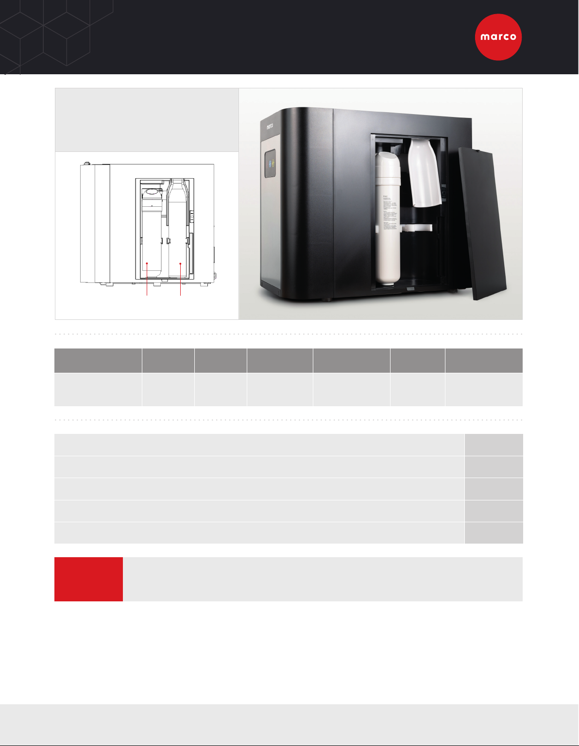
FRIIA LITE HOT/COLD/SPARKLING & FRIIA LITE HOT/COLD
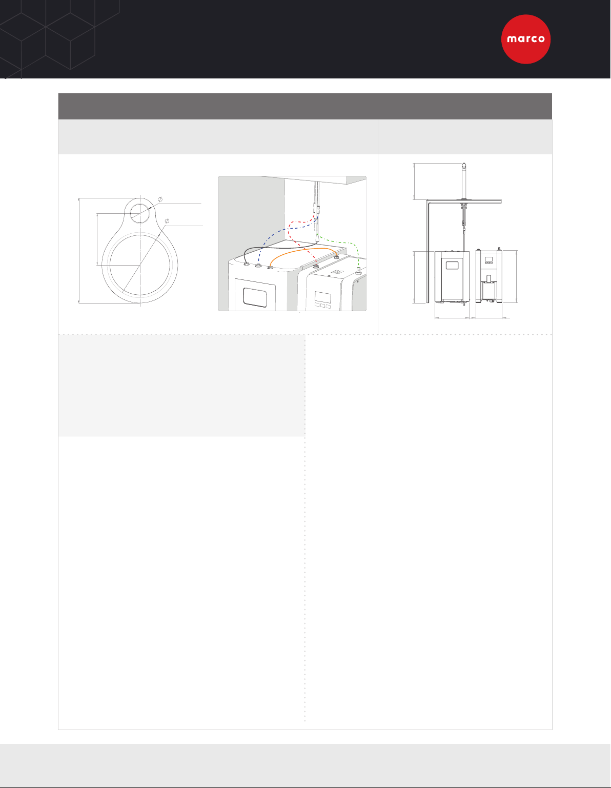
COUNTER CUT-OUT WITH DRIP TRAY FRIIA LITE HCS 5000203
FRIIA LITE HC 5000204
287mm
279mm 210mm
421mm
412mm
4”/100mm
For drip-tray only
1.25”/32mm
3.25”/82.5mm
6.6”/168mm
VENTILATION REQUIREMENTS
FRONT VENTILATION: Ventilation grilles cut out of standard cabinet door.
SIDE VENTILATION: Ventilation grilles cut out of standard 600mm
cabinet. Grilles may be fitted on either side as long as they ventilate
into an open unobstructed area.
BASE VENTILATION: Ventilation grilles cut in base panel and base
plinth, a grille must also be cut out at the top of the cabinet.
• At least 2 x vents 260mm/10.2” w x 65mm/2.5 h
UNPACKING INSTRUCTIONS
> The chiller must be handled only in a vertical position. Transporting
the appliance in a horizontal position can cause severe damage to
the refrigerator.
> Remove the exterior and interior packing. Packing materials
(especially any plastic bags) should be stored out of the reach
of children, as a potential source of danger. When disposing
packaging parts, please follow current regulations on the matter,
separating carton from plastic parts.
> Always check that the equipment that is delivered corresponds to
the model indicated in the accompanying document.
> The equipment is shipped in a cardboard box. Once the packaging
has been removed, check the equipment has not been damaged in
transit; if damage is found, notify the carrier.
ELECTRICAL INSTALLATION PROCEDURE
When installing the machine, always observe the local regulations and
standards. The appliance is supplied with a moulded power cord. A
suitable mains power supply socket should be available within easy
access of the appliance so that it can be disconnected easily after install.
The standard machines are supplied with a UK 3-pin plug. For
EU models a 2-pin CEE-7 plug will be supplied. US models will be
supplied with the suitable plug. A suitable mains power supply socket
should be available within easy access of the appliance so that it
can be disconnected easily after install. The wires from the font are
terminated in a Mini Fit connector which will plug into a similar Mini Fit
connector mounted on the top lid of the undercounter boiler.
PLUMBING INSTALLATION PROCEDURE
> Ensure that the equipment is installed according to local plumbing
& water regulations.
> Fit a stop valve on a cold water line and attach a 3/4” BSP male
fitting, (eg. 3/4” x 1/2” 311 or washing machine type stop valve).
Suitable fittings are supplied with the kit to attach to the 3/4” BSP
fitting to connect the supplied 3/8” hose.
> Connect water supply lines following the installation drawings,
as per installation guide (starting page 14).
> In case filter systems are used verify that they satisfy the
requirements of the legislation in force.
> If the filter is new, turn on water and flush at least 10 litres
(2.5 gallon) through the filter before to connect it to the cooler;
if the filter is a used one, connect water inlet to the chiller.
> To ensure that the maximum value of pressure of 3 Bar is not
exceeded the chiller integrates a pressure reducer.
> Turn on the water to flush any impurities, dust etc from the inlet hose and
water pipe. Allow several litres through. Especially for new installations.
BEFORE USING CHILLER
> Before connecting the chiller to the power source, let it stand upright for
approximately 2-3 hours, this will reduce the possibility of a malfunction.
> Check that all installation procedures have been carried out.
> Ensure water inlet is open.
> Ensure CO2 valve is full stop.
> Before supplying power to the chiller check water and CO2 lines
do not leak.
> Plug the chiller into a suitable socket and turn the Cooling Switch
on the rear of the chiller to the ON position.
> When the unit is on, the carbonation pump starts to fill. The
carbonation device stops when it reaches the maximum level.
> If using an external CO2 Cylinder, on the pressure reducer knob, adjust
CO2 pressure to a value between 50 and 65 PSI (350 and 450 kPa) (3.5 -
4.5 bar).This value depends on the temperature of the water and on the
ambient temperature. The temperatures correspond to the CO2 pressure.
> The chiller will take aproximatly 70-120 minutes to get down to
temperature depending on the temperature of your incoming water.
The blue light on the front of the chiller remains flashing during
chilling.
> Once the blue light stops flashing and remains solid the chiller is
down to temperature and at this point you can dispense water.
> To enable the filling of lines, push the font buttons in the following order:
sparkling water, cold water & hot water until the flows appear.
> At this point you can dispense water.
COLD
(1/4”)
CHILLER TO BOILER
CONNECTOR
(1501180)
HOT
(8mm)
VENT
ELECTRICAL
(FONT CONNECTION)
FRIIA LITE HCS & FRIIA LITE HC
For more information visit www.marcobeveragesystems.com
FRIIA LITE
CO2 INSTALLATION PROCEDURE
EXTERNAL GAS CYLINDER
> The machine has an external gas connection for 8mm hose (not provided) in the rear; you must supply appropriate
pressure gas (0.4MPa). Only use super-dry, food grade CO2.
> Before connecting the pressure reducer to the gas cylinder, always vent any dirt from the valve. Close the cylinder
valve after few seconds.
GAS CYLINDER LOCATION
To prevent the risk of injury or damage the CO2 cylinder must always be kept in a vertical position against a wall, held
in place by a chain and fixed to a bracket. Do not expose the bottle to heat sources or very low temperatures.
Filter CO2 Cylinder
There are two CO2 install options with this
chiller, either an inbuilt 360-410gr/60L gas
cylinder or an external CO2 cylinder.
INTERNAL GAS CYLINDER
> Open the side door.
> Install the CO2 cylinder into the machine.
> A compatible gas cylinder to use is the Sodastream 60L
cylinder: sodastream.co.uk/pages/co2-gas-cylinders
To CO2 canister
To Chiller
BS8 connection
Filter CO2 Cylinder
8mm push fit
connection
PRESSURE REDUCERS
> There are different type of CO2 cylinder
available. Always use a pressure reducer
suitable for the type of valve on the cylinder.
If you use CO2, especially in a small area,
ventilate the contaminated area at once.
> We advise using a Dual gauge CO2 regulator,
Marco part number 1400195.
> Check for leaks using a solution of soapy
water.
FRIIA LITE CO2 INSTALLATION PROCEDURE

Other manuals for MIX UC3

2

This manual suits for next models

5

Other Marco Water System manuals

Marco MIX UC3 User manual

Marco

Marco MIX UC3 User manual

Marco FRIIA C User manual

Marco

Marco FRIIA C User manual

Marco MIX UC3 User manual

Marco

Marco MIX UC3 User manual

Marco 1000859 User manual

Marco

Marco 1000859 User manual

Marco FRIIA HC User manual

Marco

Marco FRIIA HC User manual

Marco UNA FONT User manual

Marco

Marco UNA FONT User manual

Popular Water System manuals by other brands

Orbinox RB manual

Orbinox

Orbinox RB manual

Bayrol PoolManager Chlorine user manual

Bayrol

Bayrol PoolManager Chlorine user manual

T&S B-0133-B Installation and maintenance instructions

T&S

T&S B-0133-B Installation and maintenance instructions

AmeriWater MRO3 Operation & maintenance manual

AmeriWater

AmeriWater MRO3 Operation & maintenance manual

Field Controls CLEARWAVETM WATER CONDITIONER CW-HD-4 installation manual

Field Controls

Field Controls CLEARWAVETM WATER CONDITIONER CW-HD-4 installation manual

Vivreau Top Series operating manual

Vivreau

Vivreau Top Series operating manual

salmson NSB Installation and starting instructions

salmson

salmson NSB Installation and starting instructions

EcoWater ES9120R owner's manual

EcoWater

EcoWater ES9120R owner's manual

Thermo Scientific Smart2Pure 3 operating instructions

Thermo Scientific

Thermo Scientific Smart2Pure 3 operating instructions

EcoWater Series 2000 owner's manual

EcoWater

EcoWater Series 2000 owner's manual

Halsey Taylor HOF14A-FR-Q 1D Series owner's manual

Halsey Taylor

Halsey Taylor HOF14A-FR-Q 1D Series owner's manual

Energie Aquapura 6 Installation and user manual

Energie

Energie Aquapura 6 Installation and user manual

Elkay EZH20 LZWSMD* Installation, care & use manual

Elkay

Elkay EZH20 LZWSMD* Installation, care & use manual

Kessel EasyClean NS Series Installation and operating instructions

Kessel

Kessel EasyClean NS Series Installation and operating instructions

Rain Soft UF Series owner's manual

Rain Soft

Rain Soft UF Series owner's manual

Pure-Pro M500 user manual

Pure-Pro

Pure-Pro M500 user manual

MYPV AC ELWA-E Operation manual

MYPV

MYPV AC ELWA-E Operation manual

PerkinElmer Peltier N1015158 operating manual

PerkinElmer

PerkinElmer Peltier N1015158 operating manual

manuals.online logo
manuals.online logoBrands
  • About & Mission
  • Contact us
  • Privacy Policy
  • Terms and Conditions

Copyright 2025 Manuals.Online. All Rights Reserved.