Cub Cadet Snow Cab/Sun Shade User manual

CUB CADET LLC, P.O. BOX 361131 CLEVELAND, OHIO 44136-0019
OperatOr’sManual
Safe Operation Practices • Set-Up • Operation • Maintenance • Service • Troubleshooting • Warranty
WARNING
READ AND FOLLOW ALL SAFETY RULES AND INSTRUCTIONS IN THIS MANUAL
BEFORE ATTEMPTING TO OPERATE THIS MACHINE.
FAILURE TO COMPLY WITH THESE INSTRUCTIONS MAY RESULT IN PERSONAL INJURY.
Snow Cab/Sun Shade
Form No. 769-10773B
(January 6, 2020)

Customer Support
Please do NOT return the machine to the retailer or dealer without first contacting the Customer Support Department.
If you have difficulty assembling this product, have questions regarding the controls, operation, or maintenance of this machine, want
to order replacement parts/attachments/accessories, or want to view an online How-To video; you can seek help from the experts. Have
your full model number and serial number ready. Choose from the options below:
◊ Web: www.cubcadet.com/equipment/cubcadet/service-and-parts
◊ Phone: (800) 965-4CUB
◊ Mail: Cub Cadet LLC • P.O. Box 361131 • Cleveland, OH • 44136-0019
Thank you for purchasing a Cub Cadet Snow Cab/Sun Shade. It
was carefully engineered to provide excellent performance when
properly operated and maintained.
Please read this entire manual prior to operating the equipment.
It instructs you how to safely and easily set up, operate and
maintain your equipment. Please be sure that you, and any other
persons who will operate the equipment, carefully follow the
recommended safety practices at all times. Failure to do so could
result in personal injury or property damage.
All information in this manual is relative to the most recent
product information available at the time of printing. Review this
manual frequently to familiarize yourself with the equipment,
its features and operation. Please be aware that this Operator’s
Manual may cover a range of product specifications for various
models. Characteristics and features discussed and/or illustrated
in this manual may not be applicable to all models. Cub Cadet
LLC reserves the right to change product specifications, designs
and equipment without notice and without incurring obligation.
If you have any problems or questions concerning this
equipment, phone your local Cub Cadet dealer or contact us
directly. Cub Cadet’s Customer Support telephone numbers,
website address and mailing address can be found on this page.
We want to ensure your complete satisfaction at all times.
Throughout this manual, all references to LEFT, RIGHT, FRONT,
and REAR indicate that position on the tractor when facing
forward while seated in the operator seat.
Thank You
To The Owner 1
2
Safe Operations....................................................... 3
Assembly & Set-Up .................................................. 5
Warranty .................................................................12
Table of Contents

Important Safe Operation Practices 2
3
General Operation
1. Read, understand, and follow all instructions on the
machine and in the manual(s) before attempting to
assemble and operate. Keep this manual in a safe place for
future and regular reference and for ordering replacement
parts.
2. Be familiar with all controls and their proper operation.
Know how to stop the machine and disengage them
quickly.
3. Never allow children under 14 years of age to operate this
machine. Children 14 and over should read and understand
the instructions and safe operation practices in this manual
and on the machine and should be trained and supervised
by an adult.
4. Never allow adults to operate this machine without proper
instruction.
5. The snow cab/sun shade frame add height to the machine.
Low tree limbs, clothes lines, door entry ways and other
overhead structures that did not interfere with the machine
operation before, may now present a hazard. Be sure you have
adequate clearance before driving under them.
6. Check overhead clearances carefully before driving under
low hanging tree branches, wires, door openings etc.,
where the operator may be struck or pulled from the
machine, which could result in serious injury.
7. If situations occur which are not covered in this manual, use
care and good judgment. Contact your customer service
representative for assistance.
8. Breathing Carbon Monoxide can cause headaches, nausea,
fainting or death.
9. Do not block air vents as Carbon Monoxide may accumulate
inside the cabin.
10. Never run your riding mower in an enclosed space or
garage.
11. This snow cab/sun shade is designed to provide an element
of protection from seasonal weather only. it is not designed
to provide protection from noise, exhaust fumes, chemicals
or injury from collision or other accidents. This structure
does not provide roll-over protection.
12. Neither the snow cab or sun shade is intended to provide
complete protection from the sun. Use sunscreen or wear
protective clothing for additional protection.
WARNING! This symbol points out important safety instructions which, if not followed,
could endanger the personal safety and/or property of yourself and others. Read and follow
all instructions in this manual before attempting to operate this machine. Failure to comply
with these instructions may result in personal injury.
When you see this symbol. HEED ITS WARNING!
DANGER! This machine was built to be operated according to the safe operation practices in
this manual. As with any type of power equipment, carelessness or error on the part of the
operator can result in serious injury. This machine is capable of amputating hands and feet
and throwing objects. Failure to observe the following safety instructions could result in
serious injury or death.
CALIFORNIA PROPOSITION 65
WARNING! Engine Exhaust, some of its constituents, and certain vehicle components
contain or emit chemicals known to State of California to cause cancer and birth defects
or other reproductive harm.
WARNING! Battery posts, terminals, and related accessories contain lead and lead
compounds, chemicals known to the State of California to cause cancer and reproductive
harm. Wash hands after handling

4Section 2 — important Safe operation practiceS
Children
1. Tragic accidents can occur if the operator is not alert to the
presence of children. Children are often attracted to the
machine and the mowing activity. They do not understand
the dangers. Never assume that children will remain where
you last saw them.
a. Keep children out of the mowing area and in
watchful care of a responsible adult other than the
operator.
b. Be alert and turn machine off if a child enters the
area.
c. Before and while backing, look behind and down for
small children.
d. Never carry children, even with the blade(s) shut off.
They may fall off and be seriously injured or interfere
with safe machine operation.
e. Use extreme care when approaching blind corners,
doorways, shrubs, trees or other objects that may
block your vision of a child who may run into the
path of the machine.
f. To avoid back-over accidents, always disengage
the cutting blade(s) before shifting into Reverse. If
equipped, the “Reverse Caution Mode” should not
be used when children or others are around.
g. Keep children away from hot or running engines.
They can suffer burns from a hot muffler.
h. Remove key when machine is unattended to
prevent unauthorized operation.
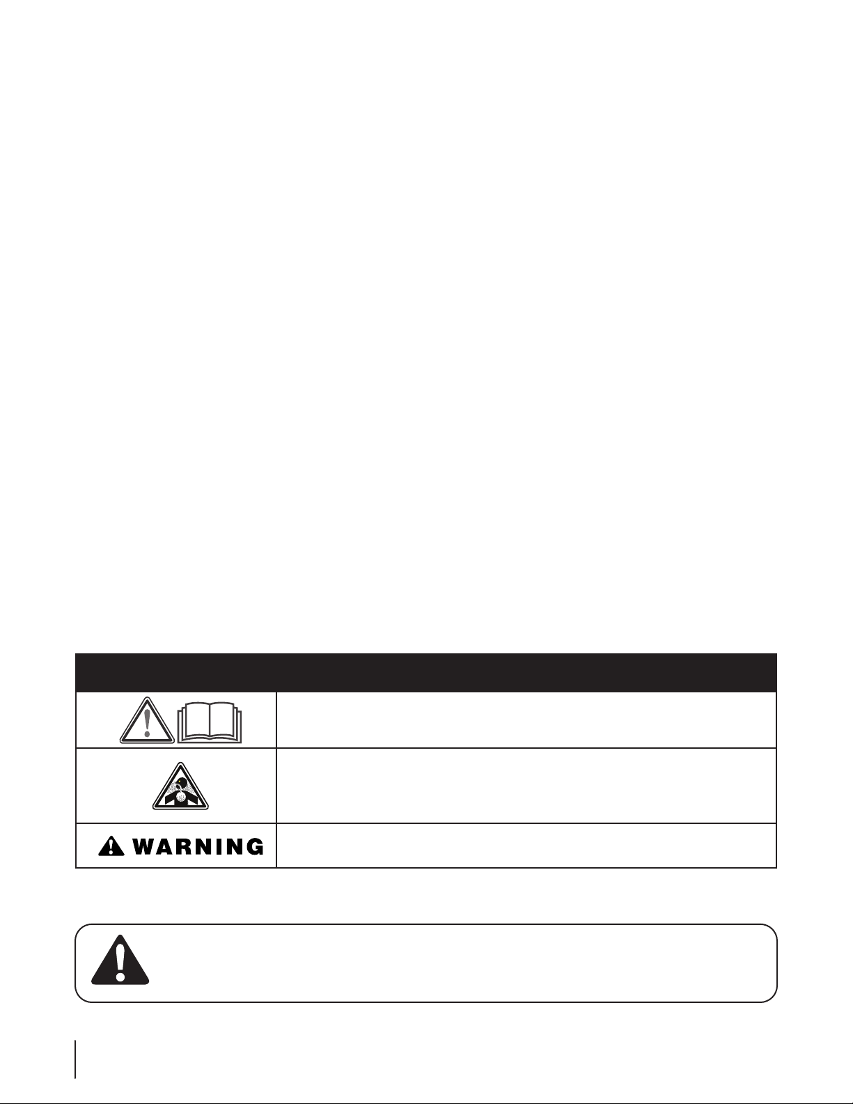
Safety Symbols
This page depicts and describes safety symbols that may appear on this product. Read, understand, and follow all instructions on the
machine before attempting to assemble and operate.
Symbol Description
READ THE OPERATOR’S MANUAL(S)
Read, understand, and follow all instructions in the manual(s) before attempting to
assemble and operate
WARNING — CARBON MONOXIDE
Breathing Carbon Monoxide can cause headaches, nausea, fainting or death. Do not block
air vents as Carbon Monoxide may accumulate inside the cabin. Never run your riding mower
in an enclosed space or garage.
WARNING — ROLLOVER
This frame will not protect against rollover.
2. Never allow children under 14 years of age to operate this
machine. Children 14 and over should read and understand
the instructions and safe operation practices in this manual
and on the machine and should be trained and supervised
by an adult.
General Service
1. Keep all nuts, bolts, and screws tight to be sure the
equipment is in safe working condition.
2. After striking a foreign object, stop the engine, disconnect
the spark plug wire(s) and ground against the engine.
Thoroughly inspect the machine for any damage. Repair
the damage before starting and operating.
3. Never attempt to make adjustments or repairs to the
machine while the engine is running.
4. Grass catcher components and the discharge cover are
subject to wear and damage which could expose moving
parts or allow objects to be thrown. For safety protection,
frequently check components and replace immediately
with original equipment manufacturer’s (O.E.M.) parts only,
listed in this manual. “Use of parts which do not meet the
original equipment specifications may lead to improper
performance and compromise safety!”
5. Maintain or replace safety and instruction labels, as
necessary.
WARNING! Your Responsibility—Restrict the use of this power machine to persons who read, understand and
follow the warnings and instructions in this manual and on the machine.
SAVE THESE INSTRUCTIONS!

Assembly & Set-Up 3
5
Contents of Carton
Figure 3-1
11
10
8
9
12
14
17
13
Hardware &
Loose Pack Items
5
3
1
2A
7
3
2B
7
6B
5
6A
4
Ref. Part Number Description Qty.
1749-05389B Rear Support 1
2A 749-05387A Rear Right Support 1
2B 749-05388A Rear Left Support 1
3749-07234 Cross Support 2
4720-05501 Center Support Rod Kit 1
5749-05384A Front Support 2
6A 649-05054A Front Right Support 1
6B 649-05055A Front Left Support 1
7649-05053A Side Support 2
8683-05220 Front Canopy Mount Plate 2
9736-0451 Sdle. Wash., .320 x .930 x .060 2
Ref. Part Number Description Qty.
10 712-04063 Flange Lock Nut, ⁄-18 2
11 712-04064 Flange Lock Nut, ⁄4-20 4
12 777X45500 Reector Labels 2 *
13 710-3180 Hex Screw, ⁄-18 x 1.75 2
14 736-3078 Fl. Wash, .344 x 1.000 x .063 2
15 736-0142 Fl. Washers, .281x.500x.063 4
NS 790-00712 Snow Cab 1 *
NS 790-00710 Sun Shade 1 *
* -- If equipped

6Section 3— ASSembly & Set-Up
5. Use two flange lock nuts (#10), two saddle
washers (#9), two flat washers (#14) and
two hex screws (#13) to mount the rear
support (#1) to the frame of the tractor as
shown in Figure 3-5.
Figure 3-5
6. Assemble the frame of the Snow Cab/Sun
Shade by connecting the numbered parts
as shown in Figure 3-1.
7. The frame pieces connect with a
spring clip inserted into the hole of the
connecting part to secure each piece
in place. Press down on the spring clip
button and slide it inside the connecting
piece until it snaps into the hole. See
Figure 3-6.
Figure 3-6
NOTE: Refer to Figure 3-1 for proper
location and assembly of the frame
pieces.
NOTE: All references to LEFT, RIGHT, FRONT,
and REAR indicate the Snow Cab/Sun Shade
position when sitting in the tractor seat in the
operator’s position.
CAUTION: Do not transport the
tractor on a trailer or in the bed of a
truck with the snow cab or sun
shade installed.
Assembly
Before beginning installation, remove all parts
from the carton to make sure everything is
present. Carton contents listed on page 5.
NOTE: Some tractors will require the use of
the Snow Cab/Sun Shade Mounting Kit (#759-
05086) in order to install. The templates to drill
the required holes and instructions are on page 9.
To order the snow cab/sun shade mounting kit
see your authorized service dealer or contact
Customer Support.
1. Using two of the flange lock nuts (Ref. part
#11), two of the washers (Ref. part #15) and
one of the front canopy mount plates (#8),
mount the front left support (#6B) to the
frame of the tractor as shown in Figure 3-2.
Figure 3-2
2. If your tractor is equipped with a drain hose
as shown below, the oil drain tube and clip
must be removed from the frame before
installing the front right support (#6A). See
Figure 3-3. The oil drain tube and clip will be
fitted onto the front right support bracket
when it is installed.
Figure 3-3
3. Repeat the mounting steps (Starting with
Step 1) on the right side of the tractor to
mount the front right support (#6A).
4. Install the oil drain tube clip onto the
front right support bracket (#6A) in the
mounting hole. See Figure 3-4.
Figure 3-4

7Section 3 — ASSembly & Set-Up
8. Assemble the canopy prior to attaching
it to the top of the frame. Insert the
cross supports (Ref. part #3) into the side
supports (Ref. part #7). Then attach the
center rod (Ref. part #4) in the mounting
holes located on the front and rear
cross supports. Then assemble the cross
support rods (Ref. part #4) with rod
connectors (Ref. part #4) and place the
ends into the mounting holes located on
the inside of the side supports.
Figure 3-7
9. Wrap the velcro around the center rod
and cross support rods.
10. Finally attach the top side supports to
the rear side supports and the front side
supports.
Installing the Sun Shade
NOTE: If you purchased the Snow Cab Kit
(19A30022100) alone, the Sun Shade attachment
(790-00710) can be ordered separately.
1. Slide the sun shade over the top of the
frame with the long mesh flap towards
the back.
2. There are four tie-down straps on the
outside corners of the sun shade; two in the
front and two in the back. Secure the front
and back of the sun shade with these straps
as shown in Figure 3-8.
Figure 3-8
3. There are two straps on the rear mesh
flap of the sun shade. Wrap these around
the rear supports and secure as shown in
Figure 3-9.
Figure 3-9
Installing the Snow Cab
NOTE: If you purchased the Sun Shade kit (Part
#19A30021100) alone, you can order the Snow
Cab attachment (790-00712) separately.
NOTE: To help remove any wrinkles in the snow
cab, leave the snow cab unfolded out in the
sun.
1. Unfold the snow cab and lay it over the top
of the frame. Make sure that the silver/gray
reflector along the upper rear of the back
window is facing towards the rear of the
tractor. See Figure 3-10.
Figure 3-10
2. Remove the backing tape on the reflector
labels and install the labels on the outside
of the cab as shown in Figure 3-11.
Figure 3-11
3. There are five clips around the base of
the snow cab, three on the back and one
each on the left and right side.
4. The rear center clip clips onto the center
of the fender. See Figure 3-12.
Figure 3-12
5. The outer rear clips clip onto the fenders
near the wheels. See Figure 3-13.
Figure 3-13

8Section 3— ASSembly & Set-Up
6. The outer front clips attach to the front
fenders near the wheels. See Figure 3-14.
Figure 3-14
7. A bungee strap runs over the front of the
hood. This strap is used to tighten the snow
cab around the hood and prevent snow
from entering the cab. The hooks of the
strap are hooked onto the hood near the
front wheels. See Figure 3-15.
Figure 3-15
8. Unzip the cab door and locate the five
straps inside the cab. There is one in the
front (near the hood) and a four along the
top. Snap the ends of each strap together
and then tighten them securely. See
Figure 3-16.
Figure 3-16
9. A pair of magnets are on the bottom
section of each side of the floor boards.
These magnets help hold the lower
portion of the snow cab against the
floorboards. See Figure 3-17.
Figure 3-17
10. Secure the two velcro tabs on the back
corners of the snow cab to ensure a tight
fit. See Figure 3-18.
Figure 3-18
11. If your tractor has a snow thrower
installed, the chute directional control can
be positioned or routed inside the cab
through the zippered opening on the left
side of the cab. See Figure 3-19.
Figure 3-19
12. The lift handle and trigger control can be
accessed by unzipping the right side of
the snow cab. See Figure 3-20.
Figure 3-20
NOTE: These zippers can also be opened
for air circulation.

9Section 3 — ASSembly & Set-Up
Drill Templates
NOTE: Some tractors will require the use
of the Snow Cab/Sun Shade Mounting Kit
(#759-05086) in order to install. To order the
snow cab/sun shade mounting kit see your
authorized service dealer or contact Customer
Support or use the paper templates to the
Right.
1. Align template A on the right side of the
tractor as shown in secure in place with
the hex screw, nut and screw from the
Snow Cab/Sun Shade Mounting Kit. See
Figure 3-21.
Figure 3-21
2. Drill the appropriate holes with the ⁄”
drill bit provided in the Snow Cab/Sun
Shade Mounting Kit. See Figure 3-21.
3. Remove template A.
4. Align template B on the left side of the
tractor and secure in place with the hex
screws and nuts from the Snow Cab/Sun
Shade Mounting Kit. See Figure 3-22.
Figure 3-22
5. Drill the appropriate holes with the ⁄”
drill bit provided in the Snow Cab/Sun
Shade Mounting Kit. See Figure 3-22.
6. Remove template B and begin the
Assembly steps on page 6.
AB

10
Notes

11Notes

IMPORTANT: To obtain warranty coverage owner may be required
to present an original proof of purchase and applicable maintenance
records to the servicing dealer. Please see the operator’s manual for
information on required maintenance and service intervals.
The limited warranty set forth below is given by Cub Cadet LLC with
respect to new merchandise purchased or leased and used in the
United States and/or its territories and possessions, and by MTD
Products Limited with respect to new merchandise purchased or
leased and used in Canada and/or its territories and possessions
(either entity respectively, “Cub Cadet”).
Cub Cadet warrants this product (excluding its Normal Wear Parts, as
described below) against defects in material and workmanship for
a period of two (2) years commencing on the date of original retail
purchase or lease and will, at its option, repair or replace, free of
charge, any part found to be defective in materials or workmanship.
Normal Wear Parts are warranted to be free from defects in material
and workmanship for a period of thirty (30) days from the date of
original purchase or lease. Normal wear parts include, but are not
limited to items such as: belts, blades, blade adapters, grass bags,
rider deck wheels, seats and tires.
This limited warranty shall only apply if this product has been
operated and maintained in accordance with the Operator’s
Manual furnished with the product, and has not been subject to
misuse, abuse, neglect, accident, improper maintenance, alteration,
vandalism, theft, fire, water or damage because of other peril or
natural disaster. Damage resulting from the installation or use of any
part, accessory or attachment not approved by Cub Cadet for use
with the product(s) covered by this manual will void your warranty as
to any resulting damage. In addition, Cub Cadet may deny warranty
coverage if the hour meter, or any part thereof, is altered, modified,
disconnected or otherwise tampered with.
HOW TO OBTAIN SERVICE: Warranty service is available, WITH
PROOF OF PURCHASE AND APPLICABLE MAINTENANCE RECORDS,
through your local authorized service dealer. To locate the dealer in
your area:
In the U.S.A.
Check your Yellow Pages, or contact Cub Cadet LLC at P.O. Box 361131,
Cleveland, Ohio 44136-0019, call 1-877-282- 8684
or log on to our website at www.cubcadet.com.
In Canada
Contact MTD Products Limited, Kitchener, ON N2G 4J1, call 1-800-
668-1238 or log on to our website at www.mtdcanada.com.
Without limiting the foregoing, this limited warranty does not provide
coverage in the following cases:
a. Routine maintenance items such as lubricants, filters, blade
sharpening, tune-ups, brake adjustments, clutch adjustments,
deck adjustments, and normal deterioration of the exterior
finish due to use or exposure.
b. Service completed by someone other than an authorized
service dealer.
c. Cub Cadet does not extend any warranty for products sold
or exported outside of the United States and/or Canada, and
their respective possessions and territories, except those sold
through Cub Cadet’s authorized channels of export distribution.
d. Replacement parts and\or accessories that are not genuine Cub
Cadet parts.
e. Transportation charges and service calls.
f. Commercial or Institutional Use.
There are no implied warranties, including without limitation
any implied warranty of merchantability or fitness for a
particular purpose. No warranties shall apply after the
applicable period of express written warranty above. No other
express warranties beyond those mentioned above, given by
any person or entity, including a dealer or retailer, with respect
to any product, shall bind Cub Cadet. The exclusive remedy is
repair or replacement of the product as set forth above.
The terms of this warranty provide the sole and exclusive
remedy arising from the sale and/or lease of the products
covered hereby. Cub Cadet shall not be liable for any incidental
or consequential loss or damage including, without limitation,
expenses incurred for substitute or replacement lawn care
services or for rental expenses to temporarily replace a
warranted product.
Some jurisdictions do not allow the exclusion or limitation of
incidental or consequential damages, or limitations on how long an
implied warranty lasts, so the above exclusions or limitations may not
apply to you.
In no event shall recovery of any kind be greater than the amount of
the purchase price of the product sold. Alteration of safety features
of the product shall void this warranty. You assume the risk and
liability for loss, damage, or injury to you and your property and/or to
others and their property arising out of the misuse or inability to use
the product.
This limited warranty shall not extend to anyone other than the
original purchaser or to the person for whom it was purchased as a
gift.
HOW LOCAL LAWS RELATE TO THIS WARRANTY: This limited
warranty gives you specific legal rights, and you may also have other
rights that vary in different jurisdictions.
CUB CADET LLC
MANUFACTURER’S LIMITED WARRANTY
FOR SEPARATELY SOLD ATTACHMENTS AND ACCESSORIES
Cub Cadet LLC, P.O. BOX 361131 CLEVELAND, OHIO 44136-0019, Phone: 1-877-282-8684
MTD Products Limited, Kitchener, ON N2G 4J1, Phone: 1-800-668-1238
GDOC-100177 REV. B

CUB CADET LLC, P.O. BOX 361131 CLEVELAND, OHIO 44136-0019
Manual del OperadOr
Medidas de seguridad • Conguración • Funcionamiento • Mantenimiento • Servicio • Solución de problemas • Garantía
WARNING
READ AND FOLLOW ALL SAFETY RULES AND INSTRUCTIONS IN THIS MANUAL
BEFORE ATTEMPTING TO OPERATE THIS MACHINE.
FAILURE TO COMPLY WITH THESE INSTRUCTIONS MAY RESULT IN PERSONAL INJURY.
Cabina para nieve/Parasol

Servicio de Atención al Cliente
Por favor, NO devuelva la máquina al minorista o distribuidor sin ponerse en contacto primero con el
Departamento de Atención al Cliente.
En caso de tener problemas para ensamblar este producto o de tener dudas con respecto a los controles, el funcionamiento
o el mantenimiento de esta máquina,si desea pedir piezas/aditamentos/accesorios o si desea ver un video instructivo
en línea;puede solicitar la ayuda de expertos. Debe tener a mano el número de modelo y el número de serie completos.
Seleccione una de las opciones siguientes:
◊ Web: www.cubcadet.com/equipment/cubcadet/service-and-parts
◊ Teléfono: (800) 965-4CUB
◊ Correo: Cub Cadet LLC • P.O. Box 361131 • Cleveland, OH • 44136-0019
Gracias por comprar una cabina para nieve/parasol Cub
Cadet. Ha sido cuidadosamente diseñada para brindar
excelente rendimiento si se la hace funcionar y se la mantiene
correctamente.
Por favor lea todo este manual antes de hacer funcionar el
equipo. El manual le indica cómo configurar, operar y mantener
el equipo de manera fácil y segura. Por favor asegúrese de que
usted, y cualquier otra persona que haga funcionar el equipo,
siga atentamente y en todo momento las medidas de seguridad
recomendadas. De lo contrario, se podrían producir lesiones
personales o daños materiales.
Toda la información contenida en este manual hace referencia
a la más reciente información de producto disponible en el
momento de la impresión. Revise el manual frecuentemente para
incluidas y/o ilustradas en este manual no se apliquen a todos
los modelos. Cub Cadet LLC se reserva el derecho de modificar
las especificaciones de los productos, los diseños y el equipo sin
previo aviso y sin generar responsabilidad por obligaciones de
ningún tipo.
Si tiene algún problema o duda con respecto a este equipo, llame
a su distribuidor Cub Cadet local o comuníquese directamente
con nosotros. En esta página encontrará los números de teléfono,
la dirección del sitio web y la dirección postal de la Atención al
cliente de Cub Cadet. Queremos garantizar su entera satisfacción
en todo momento.
En todo este manual, todas las referencias a IZQUIERDA,
DERECHA, ADELANTE y ATRÁS indican esa posición en el tractor
desde el asiento del operador, mirando hacia adelante.
Muchas gracias
Al propietario 1
14
Funcionamiento seguro........................................15
Montaje y Conguración..................................... 17
Garantía............................................................... 22
Índice

Importantes medidas de seguridad 2
15
Operación general
1. Lea, entienda y cumpla todas las instrucciones incluidas en
la máquina y en el(los) manual(es) antes de intentar realizar
el montaje de la unidad y utilizarla. Guarde este manual
en un lugar seguro para consultas futuras y periódicas, así
como para solicitar repuestos.
2. Familiarícese con todos los controles y con el uso adecuado
de los mismos. Sepa cómo detener la máquina y desactivar
los controles rápidamente.
3. No permita nunca que los niños menores de 14 años de
edad utilicen esta máquina. Los niños de 14 años de edad
en adelante deben leer y entender las instrucciones de
funcionamiento y las normas de seguridad contenidas en
este manual y en la máquina, y deben ser entrenados y
supervisados por un adulto.
4. Nunca permita que los adultos operen esta máquina sin
recibir antes la instrucción apropiada.
5. El bastidor de la Cabina para nieve/parasol agrega altura
a la máquina. Las ramas bajas de los árboles, las sogas
para tender ropa, el paso de las puertas y otras estructuras
aéreas que antes no interferían con el funcionamiento de la
máquina, ahora pueden representar un peligro. Asegúrese
de que hay lugar suficiente para pasar antes de conducir
debajo de ellos.
6. Revise la holgura superior antes de conducir debajo de
ramas bajas, cables, cerramientos de puertas, etc., donde
el operador puede golpearse o ser tirado de la máquina, lo
que podría resultar en lesiones graves.
7. Si se presentan situaciones que no están previstas en este
manual, tenga cuidado y use el sentido común. Póngase en
contacto con su representante de atención al cliente para
obtener ayuda.
8. Inhalar monóxido de carbono puede provocar dolores de
cabeza, náuseas, desmayos o la muerte.
9. No obstruya las ventilaciones ya que el monóxido de
carbono puede acumularse en el interior de la cabina.
10. Nunca haga funcionar el tractor cortacésped en un lugar
cerrado o un garaje.
11. La presente Cabina para nieve/parasol está diseñada para
brindar un elemento de protección contra las condiciones
climáticas estacionales únicamente. No está diseñada
para brindar protección contra ruidos, gases de escape,
productos químicos ni lesiones como consecuencia de
un choque u otros tipos de accidentes. Esta estructura no
brinda protección contra vuelcos.
12. Ni la Cabina para nieve ni el parasol están diseñados para
brindar una protección completa contra el sol. Utilice
protector solar o vestimenta de protección para una mayor
protección.
¡ADVERTENCIA! ESTE SÍMBOLO INDICA INSTRUCCIONES DE SEGURIDAD IMPORTANTES QUE, DE NO
SEGUIRSE, PODRÍAN PONER EN PELIGRO SU SEGURIDAD PERSONAL Y/O SU PROPIEDAD O LAS DE
TERCEROS. LEA Y CUMPLA TODAS LAS INSTRUCCIONES DE ESTE MANUAL ANTES DE INTENTAR HACER
FUNCIONAR ESTA MÁQUINA. SI NO RESPETA ESTAS INSTRUCCIONES PUEDE PROVOCAR LESIONES
PERSONALES.CUANDO VEA ESTE SÍMBOLO. ¡RESPETE LA ADVERTENCIA!
¡PELIGRO! Esta máquina fue construida para ser operada de acuerdo con las prácticas de
operación segura de este manual. Al igual que con cualquier tipo de equipo de potencia, el
descuido o error por parte del operador puede provocar lesiones graves. Esta máquina es
capaz de amputar manos y pies y arrojar objetos. El incumplimiento de las siguientes
instrucciones de seguridad puede provocar lesiones graves o la muerte.
PROPOSICIÓN 65 DE CALIFORNIA
¡ADVERTENCIA! El escape del motor, algunos de los elementos del mismo y algunoscomponentes del vehículo
contienen o liberan sustancias químicas que según el Estado de California pueden producir cáncer, defectos de
nacimiento u otros problemas reproductivos.
¡ADVERTENCIA! Los bornes, los terminales y los accesorios relacionados de la batería contienen plomo
y compuestos de plomo, sustancias químicas que según lo establecido por el Estado de California
causan cáncer y daños en el sistema reproductivo. Lávese las manos después de estar en contacto con estos
componentes.

16 Sección 2 — importanteS medidaS de Seguridad
Niños
1. Pueden ocurrir accidentes trágicos si el operador no está
atento a la presencia de niños. Por lo general, los niños
se sienten atraídos por la máquina y su actividad. No
entienden los riesgos ni los peligros. Nunca suponga que
los niños permanecerán en el lugar donde los vio por
última vez.
a. Mantenga a los niños fuera del área de corte y bajo
estricta vigilancia de un adulto responsable además
del operador.
b. Esté alerta y apague la máquina si un niño ingresa al
área.
c. Antes de moverse hacia atrás y mientras lo hace,
mire hacia atrás y abajo para ver que no haya niños.
d. Nunca transporte niños, ni siquiera con las cuchillas
desactivadas. Podrían caerse y resultar gravemente
heridos o interferir con la operación segura de la
máquina.
e. Tenga mucho cuidado al aproximarse a las esquinas
ciegas, puertas, arbustos, árboles u otros objetos
que puedan obstaculizarle la vista de un niño que
pudiese correr al encuentro de la máquina.
f. Para evitar accidentes retrocediendo, siempre
desacople las cuchillas antes de cambiar a marcha
atrás. Si está equipado, el “Modo de marcha atrás
con precaución” no se debe usar cuando hay niños y
otras personas alrededor.
g. Mantenga a los niños alejados de los motores en
marcha o calientes. Pueden sufrir quemaduras con
un silenciador caliente.
h. Retire la llave cuando la máquina quede sin
vigilancia para evitar el funcionamiento no
autorizado.
Símbolos de seguridad
En esta página se presentan y describen los símbolos de seguridad que pueden aparecer en este producto. Lea, comprenda y siga
todas las instrucciones incluidas en la máquina antes de intentar armarla y hacerla funcionar.
Símbolo Descripción
LEA LOS MANUALES DEL OPERADOR
Lea, entienda y cumpla todas las instrucciones incluidas en los manuales antes de realizar el
montaje de la unidad y utilizarla
ADVERTENCIA — MONÓXIDO DE CARBONO
Inhalar monóxido de carbono puede provocar dolores de cabeza, náuseas, desmayos o la muerte.No
obstruya las ventilaciones ya que el monóxido de carbono puede acumularse en el interior de
la cabina. Nunca haga funcionar el tractor cortacésped en un lugar cerrado o un garaje.
ADVERTENCIA — VUELCO
Esta estructura no protege contra vuelcos.
2. No permita nunca que los niños menores de 14 años de
edad utilicen esta máquina. Los niños de 14 años de edad
en adelante deben leer y entender las instrucciones de
funcionamiento y las normas de seguridad contenidas en
este manual y en la máquina, y deben ser entrenados y
supervisados por un adulto.
Servicio general
1. Mantenga todos los pernos, tuercas y tornillos bien
ajustados para asegurarse de que la máquina se encuentra
en condiciones seguras de funcionamiento.
2. Después de golpear algún objeto extraño, detenga el
motor, desconecte los cables de la bujía y conéctelos
a tierra con el motor. Inspeccione minuciosamente la
máquina para ver si está dañada. Repare el daño antes de
volver a arrancar y operar la máquina.
3. Nunca intente hacer ajustes o arreglos con el motor en
marcha.
4. Los componentes del colector de césped y la cubierta
de descarga están sujetos a desgaste y daños que
podrían dejar expuestas piezas móviles o permitir que
se arrojen objetos. Para proteger su seguridad, verifique
frecuentemente todos los componentes y reemplácelos
inmediatamente sólo por repuestos de los fabricantes del
equipo original (O.E.M.) listados en este manual. “El us de
repuestos que no cumplen con las especificaciones del
equipo original puede resultar en rendimiento inadecuado
y puede comprometer la seguridad”.
5. Mantenga o reemplace las etiquetas de seguridad e
instrucciones según sea necesario.
¡ADVERTENCIA! SU RESPONSABILIDAD. ESTA MÁQUINA MOTORIZADA SÓLO PUEDE SER USADA POR
PERSONAS QUE LEAN, COMPRENDAN Y RESPETEN LAS ADVERTENCIAS E INSTRUCCIONES QUE APARECEN EN
ESTE MANUAL Y EN LA MÁQUINA.
¡GUARDE ESTAS INSTRUCCIONES!

Montaje y configuración 3
17
Contenido de la caja
Figure 3-1
11
10
8
9
12
14
17
13
Hardware &
Loose Pack Items
5
3
1
2A
7
3
2B
7
6B
5
6A
4
Ref. Part Number Description Qty.
1749-05389B Soporte trasero 1
2A 749-05387A Soporte trasero derecho 1
2B 749-05388A Soporte trasero izquierdo 1
3749-07234 Soporte transversal 2
4720-05501 Kit de barra de soporte central 1
5749-05384A Soporte delantero 2
6A 649-05054A Soporte delantero derecho 1
6B 649-05055A Soporte delantero izquierdo 1
7649-05053A Soporte lateral 2
8683-05220 Placa de montaje de cúpula delantera 2
9736-0451 Arandela cóncava, 0.320 x 0.930 x 0.060 2
Ref. Part Number Description Qty.
10 712-04063 Tuerca de seguridad con brida 5⁄16-18 2
11 712-04064 Tuerca de seguridad con brida 1⁄4-20 4
12 777X45500 Etiquetas refractantes 2 *
13 710-3180 Tornillo hexagonal, 5⁄16-18 x 1.75 2
14 736-3078 Arandela plana, 344 x 1.000 x 0.063 2
15 736-0142 Arandela plana, .281x.500x.063 4
NS 790-00712 Cabina para nieve 1 *
NS 790-00710 Parasol 1 *
* -- Si es parte del equipo
Herrajes y
artículos sueltos

18 Sección 3 — Montaje yconfiguración
Figure 3-5
6. Ensamble el bastidor de la Cabina para
nieve/parasol, para lo que debe conectar
las piezas numeradas como se indica en la
Figura 3-1.
7. Las piezas del bastidor se conectan con
un enganche de resorte que se inserta
en el orificio de la pieza conectora a fin
sujetar cada pieza en su lugar. Oprima el
botón del enganche de resorte y deslícelo
dentro de la pieza conectora hasta que
entre a presión en el orificio. Consulte la
Figura 3-6.
Figure 3-6
NOTA: Consulte la Figura 3-1 para
conocer la ubicación y el montaje
correctos de las piezas del bastidor.
NOTA: Todas las referencias a IZQUIERDA,
DERECHA, ADELANTE y ATRÁS indican la
posición relativa de la Cabina para nieve/
parasol desde el asiento del tractor, en la
posición del operador.
PRECAUCIÓN: No transporte el
tractor sobre un remolque ni en la
caja de un camión con la cabina
para nieve/el parasol colocados.
Montaje
Antes de comenzar la instalación, retire todas
las piezas de la caja para asegurarse de que
tiene todo. En la caja 5 se enumera el contenido
de la caja.
NOTA: En algunos tractores es necesario usar
el Kit de montaje (n.° 759-05086) de la Cabina
para nieve/parasol para su instalación. Las
plantillas para perforar los orificios requeridos
y las instrucciones están en la página 14. Para
pedir el kit de montaje de la Cabina para
nieve/parasol, consulte al distribuidor de
mantenimiento autorizado o comuníquese con
el Servicio de Atención al Cliente.
1. Usando dos de las tuercas de seguridad con
brida (Ref. Parte # 11), dos de las arandelas
(Ref. Parte # 15) y una de las placas de
montaje del dosel delantero (# 8), monte el
soporte delantero izquierdo (# 6B) al marco
del tractor como se muestra en la Figura
3-2.
Figure 3-2
2. Antes de instalar el soporte delantero
derecho (n.° 6A), se deben extraer
del bastidor el enganche y el tubo de
drenaje de aceite. Consulte la Figura
3-3. El enganche y el tubo de drenaje de
aceite se deben colocar en la ménsula del
soporte delantero derecho al momento
de la instalación.
Figure 3-3
3. Repita los pasos de montaje
(comenzando con el paso 1) en el lado
derecho del tractor a fin de montar el
soporte delantero derecho (n.° 6A).
4. Instale el enganche del tubo de drenaje
de aceite en la ménsula del soporte
delantero derecho (n.° 6A), en el orificio
de montaje. Consulte la Figura 3-4.
Figure 3-4
5. Use dos tuercas de seguridad con brida
(n.° 10), dos arandelas cóncavas (n.°
9), dos arandelas planas (n.° 13) y dos
tornillos hexagonales (n.° 14) para montar
el soporte trasero (n.° 1) en el bastidor
del tractor como se indica en la Figura
3-5.Installez l’attache dans le trou de
montage du support avantdroit (Réf. 6A).
Voir Figure 3-5.

19Sección 3 — Montaje yconfiguración
8. Ensamble el dosel antes de colocarlo en
la parte superior del marco. Inserte los
soportes cruzados (Ref. Parte # 3) en los
soportes laterales (Ref. Parte # 7). Luego,
conecte la varilla central (Ref. Parte #
4) en los orificios de engarce ubicados
en los soportes cruzados delantero y
trasero. Luego ensamble las varillas de
soporte cruzadas (Ref. Parte # 4) con los
conectores de varilla (Ref. Parte # 4) y
coloque los extremos en los orificios de
montaje ubicados en el interior de los
soportes laterales.
Figure 3-7
9. Envuelva el velcro alrededor de la varilla
central y cruce las varillas de soporte.
10. Finalmente, fije los soportes laterales
superiores a los soportes laterales
posteriores y los soportes laterales
frontales.
Instalación del parasol
NOTA: Si adquirió el Kit de la cabina para nieve
(19A30022100) solo, el accesorio de Parasol
(790-00710) se puede pedir por separado.
1. Deslice el parasol sobre la parte superior del
bastidor con la aleta larga de malla hacia la
parte de atrás.
2. Hay ocho correas de velcro en el interior
del parasol; cuatro en la parte de adelante
y cuatro en la parte de atrás. Sujete la parte
delantera y trasera del parasol con dichas
correas como se indica en la Figura 3-8.
Figure 3-8
3. Hay dos correas en la aleta de malla
trasera del parasol. Envuelva estos
alrededor de los soportes traseros y
asegúrelos como se muestra en la Figura
3-9.
Figure 3-9
Instalación de la Cabina para nieve
NOTA: Si adquirió el Kit de parasol (n.° de
pieza 19A30021100) solo, puede pedir
el accesorio de Cabina para nieve (790-
00712) por separado.
NOTA: Para ayudar a eliminar las
arrugas de la Cabina para nieve, déjela
desplegada afuera al sol.
1. Despliegue la Cabina para nieve y
extiéndala sobre la parte superior del
bastidor. Asegúrese de que la parte
refractante plateada/gris a lo largo de
la parte superior trasera de la ventanilla
trasera quede orientada hacia la parte
trasera del tractor. Consulte la Figura 3-10.
Figure 3-10
2. Quite la cinta de protección de las
etiquetas refractantes y coloque las
etiquetas en el exterior de la cabina como
se indica en la Figura 3-11.
Figure 3-11
3. Hay cinco enganches alrededor de la
base de la Cabina para nieve, tres en la
parte posterior y uno de cada uno en el
ladoizquierdo y derecho.
4. El enganche central trasero se sujeta
al centro delguardabarros. Consulte la
Figura 3-12.
Figure 3-12
5. Los enganches exteriores traseros se
sujetan al guardabarros cerca de las
ruedas. Consulte la Figura 3-13.
Figure 3-13

20 Sección 3 — Montaje yconfiguración
6. Una correa elástica pasa por el frente
del capó. Se usa dicha correa para ajustar
la Cabina para nieve alrededor del capó
y evitar que ingrese nieve a la cabina. Los
ganchos de la correa se enganchan al capó,
cerca de las ruedas delanteras. Consulte la
Figura 3-14.
Figure 3-14
7. Abra el cierre de la puerta de la cabina
y ubique las cinco correas dentro de
la cabina. Hay una en el frente (cerca
del capó) y cuatro a lo largo de la parte
superior. Abroche los extremos de las
correas entre sí y luego ajústelos bien.
Consulte la Figura 3-15.
Figure 3-15
8. Hay un par de imanes en la sección
inferior en cada lado de las placas de piso.
Dichos imanes ayudan a sostener la parte
inferior de la Cabina para nieve contra las
placas de piso. Consulte la Figura 3-16.
Figure 3-16
9. Sujete las dos correas de velcro en las
esquinas posteriores de la Cabina para
nieve a fin de asegurar que quede bien
ajustada. Consulte la Figura 3-17.
Figure 3-17
10. Si el tractor tiene instalada una máquina
quitanieves, el control direccional del
canal se puede ubicar o pasar dentro de
la cabina a través de la abertura con cierre
que está en el costado izquierdo de la
cabina. Consulte la Figura 3-18.
Figure 3-18
11. Para acceder al control de dirección y
la manija de elevación, se debe abrir el
cierre del costado derecho de la Cabina
para nieve. Consulte la Figura 3-19.
Figure 3-19
NOTA: Dichos cierres también se pueden
abrir para que circule aire.
Plantillas para perforación
NOTA: En algunos tractores es necesario usar el
Kit de montaje(n.° 759-05086) de la Cabina para
nieve/parasol para su instalación. Para pedir el
kit de montaje de la Cabina para nieve/parasol,
consulte al distribuidor de mantenimiento
autorizado o comuníquese con el Servicio de
Atención al Cliente o utilice las plantillas de
papel que se indican.
1. Se debe alinear la plantilla A del lado
derecho del tractor como se indica, se
debe sujetar en su lugar con el tornillo
hexagonal, la tuerca y el tornillo del Kit de
montaje de la Cabina para nieve/parasol.
Consulte la Figura 3-20.
Figure 3-20
Table of contents
Languages:
Popular Indoor Furnishing manuals by other brands

Crate&Barrel
Crate&Barrel Flex Series Assembly manual

AGILE
AGILE Winder 2 Column installation guide

Furniture of America
Furniture of America CM6122BK-CS Assembly instructions

Cooper Lighting
Cooper Lighting HALO DE600 Specifications

Blanco
Blanco 513-636 Specification sheet

Twin-Star International
Twin-Star International TC48-6143 Assembly instructions