Cubic COM5000-8 Instructions for use

351804-1 Rev. 100
COM5000-8 TECHNICAL MANUAL
Instruction and Maintenance Manual
COM5000-8
HF-SSB 5-kW Linear Power Amplifier
THIS DOCUMENT CONTAINS DATA WHICH IS PROPRIETARY TO, OR A TRADE SECRET OF, CUBIC
DEFENSE APPLICATIONS, INC. THIS DOCUMENT AND THE DATA CONTAINED THEREIN SHALL
NOT BE USED, DUPLICATED, DISCLOSED OR ALTERED WITHOUT THE EXPRESS WRITTEN CONSENT
OF CUBIC DEFENSE APPLICATIONS, INC. NO RIGHT, TITLE, OR INTEREST IS GRANTED, EXPRESSLY
OR BY IMPLICATION, IN OR TO ANY DATA CONTAINED HEREIN BY VIRTUE OF ITS DISCLOSURE
TO OR USE BY THE HOLDER/RECIPIENT. DISCLOSURE MAY NOT BE MADE TO ANY THIRD
PARTY FOR ANY PURPOSE. ALL STATUTORY AND COMMON LAW RIGHTS ARE HEREBY RESERVED.
Cubic Defense Applications, Inc.
9333 Balboa Ave
San Diego, CA. 92123
Telephone: (858) 505-2024 Telefax (858) 505-1593
Manual Part No. 351804-1

351804-1 Rev. 100
COM5000-8 TECHNICAL MANUAL
i
Revisions/Updates
REV
Date
Description
Approval
100
1/30/15
Initial release.
E. Wise

351804-1 Rev. 100
COM5000-8 TECHNICAL MANUAL
ii
TABLE OF CONTENTS
Section Description...............................................................................................................................Page
GENERAL .................................................................................................................................................v
CONFIGURATION............................................................................................................................................v
5-kW TRANSMITTER PERFORMANCE SPECIFICATIONS (*) ....................................................................vi
SCOPE OF MANUAL.....................................................................................................................................vii
GENERAL SAFETY INFORMATION.............................................................................................................vii
CHAPTER 1 DESCRIPTION........................................................................................................................1
1. INTRODUCTION.....................................................................................................................1
1.1 GENERAL...............................................................................................................................1
1.2 FEATURES.............................................................................................................................1
CHAPTER 2 INSTALLATION......................................................................................................................2
2.1 GENERAL...............................................................................................................................2
2.1.1 Government Regulations ........................................................................................................2
2.1.2 Inspection................................................................................................................................2
2.1.3 General Installation .................................................................................................................2
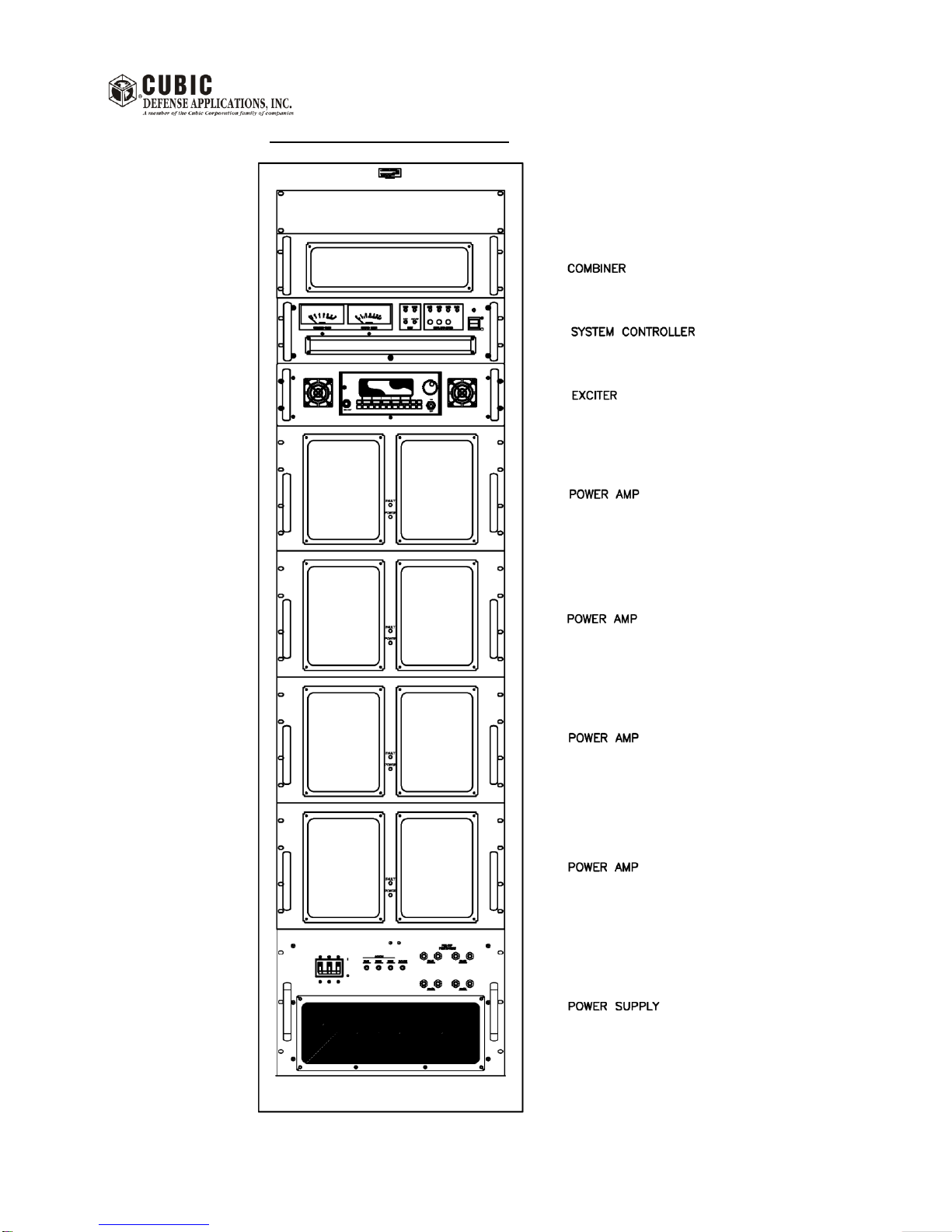
2.1.4 Rack Cabinet Installation ........................................................................................................3
2.1.4.1 Module Removal .....................................................................................................................3
2.1.4.2 Rack Cabinet Mounting...........................................................................................................4
2.1.4.3 Reconnecting Cables To Modules..........................................................................................7
2.1.4.3.1 Power Supply Module Connections........................................................................................7
2.1.4.3.2 System Controller Module Connections..................................................................................8
2.1.4.3.3 Additional Module Connections...............................................................................................9
2.1.4.4 External Connections To The Transmitter............................................................................10
CHAPTER 3 OPERATION.........................................................................................................................11
3.1. INTRODUCTION...................................................................................................................11
3.2 CONTROLS AND DISPLAYS...............................................................................................11
3.2.1 Power Supply Module ...........................................................................................................11
3.2.2 PA Module.............................................................................................................................13
3.2.4 T-4180 Exciter Module..........................................................................................................16
3.3 TRANSMITTER SYSTEM OPERATION...............................................................................16
3.3.1 General..................................................................................................................................16
3.3.2 Operating The Transmitter....................................................................................................16
3.3.3 Transmitter External Control Protocol...................................................................................17
3.3.4 Continuous Bit Operation......................................................................................................17
CHAPTER 4 FUNCTIONAL DESCRIPTION .............................................................................................25
4.1 INTRODUCTION...................................................................................................................25
4.2 COM5000-8 SYSTEM...........................................................................................................25
4.3 1.25KW PA MODULE...........................................................................................................25
4.4 COMBINER MODULE...........................................................................................................28
4.5 SYSTEM CONTROLLER MODULE .....................................................................................28
4.6 POWER SUPPLY MODULE.................................................................................................30
CHAPTER 5 MAINTENANCE....................................................................................................................31
5.1 INTRODUCTION...................................................................................................................31
5.2 RECOMMENDED TEST EQUIPMENT.................................................................................31
5.3 PERIODIC MAINTENANCE..................................................................................................31

351804-1 Rev. 100
COM5000-8 TECHNICAL MANUAL
iii
5.4 MODULE AND SUBASSEMBLY MAINTENANCE...............................................................31
5.4.1 PA Module Maintenance.......................................................................................................32
5.4.1.1 Harmonic Filter Assembly Maintenance................................................................................36
5.4.1.2 350 W Amp Assembly Maintenance.....................................................................................37
5.4.1.3 PA Controller PCB Assembly Maintenance..........................................................................38
5.4.1.4 Driver/Splitter Maintenance...................................................................................................41
5.4.1.6 1.25 kW Combiner Maintenance...........................................................................................42
5.4.1.7 Fan Interface Maintenance ...................................................................................................42
5.4.2 Combiner Module Maintenance............................................................................................43
5.4.3 System Controller Module Maintenance...............................................................................43
5.4.3.1 Driver/Splitter/ALC PCB Maintenance ..................................................................................44
5.4.3.2 System Controller PCB Maintenance....................................................................................45
5.4.3.3 System Controller Operational Adjustment...........................................................................45
5.4.4 Power Supply Module Maintenance......................................................................................51

351804-1 Rev. 100
COM5000-8 TECHNICAL MANUAL
iv
FRONT VIEW OF TRANSMITTER

351804-1 Rev. 100
COM5000-8 TECHNICAL MANUAL
v
GENERAL
This manual describes the 5 kW Linear Power Amplifier that is part of a 5 kW Transmitter. The 5 kW
Transmitter comprises the COM5000-8 power amplifier with the T-4180 Exciter as pictured above.
This manual provides a basic description of Transmitter operation. For detailed operation of the Exciter,
refer to the T-4180 manual.
CONFIGURATION
The 5-kW Transmitter (351800-1) comprises the following modules:
System Controller module 1638-1000-12
1.25 kW Power Amplifier module (Qty: 4 ea.) 351270-2
Power Supply module 351830-2
Output Combiner module L163145-1
T-4180 Exciter module 1644-1000-4

351804-1 Rev. 100
COM5000-8 TECHNICAL MANUAL
vi
5-kW TRANSMITTER PERFORMANCE SPECIFICATIONS (*)
Frequency Range: 2 to 30 MHz
Power Output: Nominal 5000 watts average and PEP
RF Input Power: + 21 dBm nominal (from T-4180 Exciter)
Gain Flatness: +/-0.5dB over 2.0 to 30 MHz (4455 - 5610 watts) with T-4180 Exciter
Intermodulation: Two-tone 3rd order IM products 32dB below PEP (26dB below each tone)
or better.
Harmonics: ≥63dBc
Impedance: 50 Ohm nominal
Load Mismatch: Unit capable of operating into load VSWR up to 3:1 (reduced output) &
survive open and shorted load. Stable with any load.
Operating Mode: Class AB
Cooling: Forced Air
Dimensions: HxDxW = 85.5" x 31.6" x 23.7" (217 x 80.3 x 60.2 cm)
Weight: 775 pounds (352 kg) approximately
Temperature range: 0 to +40 degree C (Operating)
-40 to +70 degree C (Storage)
Relative Humidity: 0 to 95% operating
Duty Cycle: Continuous
Power Requirements: 187 –240VAC (208VAC nominal), 3-phase, 47-63Hz, 50A maximum per
phase.
(*) For detailed operational and external interface specifications refer to the T-4180 manual

351804-1 Rev. 100
COM5000-8 TECHNICAL MANUAL
vii
SCOPE OF MANUAL
This Manual is intended for use by experienced technicians familiar with similar equipment. The information
it contains is current as of the printing date. Subsequent engineering changes are described in
supplementary Instruction Manual Revisions issued as needed. The applicable schematic diagram is
updated and the changes are described in a revision column on the diagram.
GENERAL SAFETY INFORMATION
The following are general safety precautions that are not related to any specific procedures and therefore do
not appear elsewhere in this publication. These are recommended precautions that personnel must
understand and apply during many phases of operation and maintenance.
KEEP AWAY FROM LIVE CIRCUITS
Personnel must at all times observe all safety precautions. Do not replace components or make adjustments
inside the equipment with the high voltage supply turned on. Under certain conditions, the potential for
danger may exist when the power control is in the OFF position due to charges retained by capacitors. To
avoid severe shock or injuries, always remove power and ground a circuit before touching it.
DO NOT SERVICE OR MAKE ADJUSTMENTS ALONE
Under no circumstance should any person reach into the enclosure for the purpose of servicing or making
adjustments to the equipment except in the presence of someone who is capable of rendering aid.
RESUSCITATION
Personnel working with or near high voltages should be familiar with modern methods of resuscitation.
HANDLING
To prevent personal injury or damage to the equipment, ensure the following lifting weights are not
exceeded. Items of 40 lb (18kg) or less require one person for handling. Items of 40 to 70 lb (18 to 32kg)
require two people for handling. Any items greater than 70 lb (32kg) require at least two people or a power
lifting device.
To avoid personal injury, at least two people are required to install bulky items into equipment cabinets.
WARNING
When operated into an antenna, this equipment may produce electromagnetic fields in close proximity to the
antenna that are in excess of Occupational Safety and Health Administration (OSHA) recommended
maximum limits.

351804-1 Rev. 100
COM5000-8 TECHNICAL MANUAL
viii
In addition, do not operate this equipment near electrical blasting caps or in an explosive atmosphere.
All equipment must be properly grounded according to installation instructions for safe operation.
Compressed air used for cleaning purposes shall not exceed 30 psi (207 kPa) and then shall be used only
when goggles or face shields are used for personnel eye protection.
CAUTION
This equipment contains electrostatic discharge sensitive (ESDS) devices. Special handling methods and
materials must be used to prevent equipment damage.

351804-1 Rev. 100
COM5000-8 TECHNICAL MANUAL
1
CHAPTER 1
DESCRIPTION
1. INTRODUCTION
1.1 GENERAL
The COM5000-8 transmitter is comprised of four 1.25kW PA Modules, a 3-phase power supply module, a
4-Way Combiner module, a System Controller module and a T-4180 exciter module. The modules are
enclosed in a standard 19” rack cabinet.
The COM5000-8 is capable of delivering a nominal output power of 5000 watts over the frequency range of
2 to 30 MHz.
1.2 FEATURES
a) Continuous duty cycle voice operation.
b) Gradual reduction of output power in case of failure in a PA module.
c) Extensive BIT.
d) FCC Part 87 and Part 15 certified. FCC ID # 2AFTMCOM5000-8.

351804-1 Rev. 100
COM5000-8 TECHNICAL MANUAL
2
CHAPTER 2
INSTALLATION
2.1 GENERAL
2.1.1 Government Regulations
Ensure that the use of the 5-kW Transmitter satisfies government regulation. In most countries, radio
transmitters may be adjusted only by persons holding a suitable government license or by personnel
working under their immediate supervision.
Similarly, most countries require that the power output of a transmitter not exceed that required for
satisfactory performance considering local conditions and the area to be served.
Also, frequency and power of a base station transmitter must be checked before it is placed in service, and
must be rechecked every year thereafter; the results of these checks must be recorded in a permanent log
available for inspection by government personnel.
2.1.2 Inspection
Carefully inspect the 5-kW Transmitter immediately upon receipt, and notify the shipper of any damage
incurred in transit. If damage has occurred and it is necessary to have the system serviced, return the
equipment to:
Cubic Defense Applications, Inc.
9333 Balboa Avenue
San Diego, CA. 92123
USA
Office #: (858) 505-2130
FAX #: (858) 277-1878
2.1.3 General Installation
Select the mounting location for convenience of access for electrical connections and for maintenance.
Keep the antenna cable as short as possible to minimize losses. The selected location should be clean, dry
and well ventilated. Do not locate the Transmitter in close proximity to strong electrical fields produced by
brush motors and generators, welders, etc.
The Transmitter rack cabinet may be placed on any sturdy, horizontal surface. No preliminary internal wiring
connections are required before installing the amplifier.
Make sure that adequate cooling is provided. Air intake is from the front and exhaust is from the rear
ventilated door of the rack cabinet. Be careful to prevent exhaust air from being re-circulated into the
air intake.
The PA module fans produce an airflow of ≈400 CFM (190 l/s) and the power supply module fans produce
an airflow of ≈ 300 CFM (140 l/s). The Combiner module fans produce an airflow of ≈ 220 CFM (100 l/s) and
the System Controller module fan produces an airflow of ≈ 35 CFM (16 l/s). The Exciter module airflow is 15
CFM (7 l/s). The total air flow requirement is approximately 2200 CFM (1000 l/s).

351804-1 Rev. 100
COM5000-8 TECHNICAL MANUAL
3
2.1.4 Rack Cabinet Installation
Install the Transmitter by first installing the rack cabinet in its intended location. It may be necessary first to
remove modules from the rack cabinet in order to reduce cabinet weight or to fasten the cabinet to the floor.
2.1.4.1 Module Removal
a) Remove the modules starting with the top module and proceed towards the bottom module. Work
only with one module at a time - keep all other modules secured in the rack cabinet while removing
a module.
b) To remove a module, start by removing the retaining screws that secure the module front panel to
the rack cabinet. After removing all the screws, slowly pull out the module until the rack slides are
fully extended and locked in this position.
c) Disconnect all the cables (coaxial and control cables and ground wires) from the rear panel of the
module (see para. 2.1.4.3)
d) Disengage the locking mechanism on both of the slides by pushing in the “locks”. Then pull the
module slowly out and away from the slides.
e) When removing a PA module (weight = 74 lbs./34 kg) or a Power Supply module (weight = 65
lbs./30 kg), two man lift is recommended to facilitate handling.
f) When removing the Power Supply module, observe the following:
WARNING:
The rack cabinet must be stable while removing modules. Failure to secure the rack cabinet to
prevent it from tipping over may cause serious injuries or death
DANGER:
Before removing AC connections from
the Power Supply terminal block, make
sure that the
AC LINE voltage has been removed

351804-1 Rev. 100
COM5000-8 TECHNICAL MANUAL
4
2.1.4.2 Rack Cabinet Mounting
Prior to installation of the rack cabinet, the location must be prepared to accept mounting bolts in the
locations shown in figure 2.1.4.2A. All external cables are routed through the large cable entry brush strip
opening at the lower rear of the cabinet.
To access the bolt-down brackets, remove the 3 floor plates near the bottom inside of the cabinet. It may
also be helpful to remove the plinth base covers that clip onto the legs at the bottom of the rack. They can
be pulled off and snapped back on. Align the rack carefully such that the four 3/8”(or 10mm) mounting bolts
can be inserted through the holes in the bolt-down brackets in the bottom of the cabinet. See figure 2.4.1.2A
for dimensions for placing the floor bolts. Note that the bolt-down brackets can be rotated to different
positions if desired.
Air exhaust for the rack cabinet is at the rear through the perforated door.
When the rack cabinet is secured to the floor, the floor plates, plinth base covers and modules can be
installed. Install the modules starting with the bottom module and proceed towards the top module. Work
only with one module at a time - make sure that each module is secured in the rack cabinet before installing
the next module.
For module locations, see figure 2.1.4.2B.
The Power Supply module must be installed first.
Proceed as follows:
a) Pull out both cabinet rack slides (left and right) for the Power Supply. Make sure the rack slides are
pulled out all the way until they lock into place.
b) Insert the Power Supply module rack slides into the cabinet rack slides.
c) Gently push the module into the rack cabinet and secure with #10-32 retaining screws.
Proceed to install the remaining modules from the bottom up, in accordance with figure 2.1.4.2B.

351804-1 Rev. 100
COM5000-8 TECHNICAL MANUAL
5
0
31.6
0
23.7
19
28.7
21.9
24
Typical Bolt Hole Pattern
Bolt-down brackets
can be rotated 360°
Pivot radius = 2.75
Slot size = 1.2 x 0.4
All dimensions
are in inches
Figure 2.1.4.2A. Rack Cabinet Mounting Hole Locations

351804-1 Rev. 100
COM5000-8 TECHNICAL MANUAL
6
83.1”(211cm)
23.7”(60.2cm)
Figure 2.1.4.2B. Rack Cabinet Module Location
Power Supply
Module
(7U)
1.25 kW PA Module
#4
(6U)
T-4180 Exciter
Module (3U)
System Controller
Module (3U)
4-Way Combiner
Module (3U)
Blank Panel
(2U)
1.25 kW PA Module
#3
(6U)
1.25 kW PA Module
#2
(6U)
1.25 kW PA Module
#1
(6U)
2.25” (5.7cm)
Lifting Eyes (4X)

351804-1 Rev. 100
COM5000-8 TECHNICAL MANUAL
7
2.1.4.3 Reconnecting Cables To Modules
The connections are shown on the Transmitter Interconnect Wiring Diagram in schematic form (see figure
5.1). Cables are secured to cable retractors and are ready to be connected to modules except for the
following large coax cables:
a. PA Module RF output coax cables (qty.4) are connected between the PA modules and the Combiner
module.
b. Combiner output coax is connected between the Combiner and the Antenna connector.
Connection to the individual modules is described below.
2.1.4.3.1 Power Supply Module Connections
Connections to the Power Supply module rear panel terminal block are shown below:
L3 L2 L1
The AC LINE Input is connected as follows: L1: Line 1 (black)
L2: Line 2 (red)
L3: Line 3 (blue)
: Ground (green)
The System Controller and Exciter module AC Line inputs connect to J2 of the Power Supply module
through a splitter cable.
The 50V DC NEG (-) connections from the four PA modules are attached to the Power Supply output
terminal bus bar with a 3/8” bolt. The terminal lug must directly contact the bus bar (no washers between the
lug and the bus bar). Tighten the bolt securely.
The 50V DC POS (+) connectors connect to J3A and J3B.
The supply control cable 9 Pin DSUB plug connects to Power Supply connector J4.

351804-1 Rev. 100
COM5000-8 TECHNICAL MANUAL
8
2.1.4.3.2 System Controller Module Connections
System
Controller
Connector
Label
System
Controller
Connector
Type
Connected
to:
Module
Connector
Label
Module
Connector
Type
RF Output
J6-1
BNC
PA module #1
RF INPUT
J1
BNC
RF Output
J6-2
BNC
PA module #2
RF INPUT
J1
BNC
RF Output
J6-3
BNC
PA module #3
RF INPUT
J1
BNC
RF Output
J6-4
BNC
PA module #4
RF INPUT
J1
BNC
RF INPUT
J5
BNC
T-4180
Exciter
OUTPUT
J3
BNC
Supply Control
J8
9-pin
DSUB
Power Supply
Module
J4
9-pin
DSUB
Combiner
Control
J1
9-pin
DSUB
Combiner
module
Control
J6
9-pin
DSUB
PA Control
J7
37-pin
DSUB
PA module
#1, 2, 3 and 4
PA Control
J3
15-pin
DSUB
Exciter Interface
J3
15-pin
DSUB
T-4180
Exciter
PA Control
J5
15-pin
DSUB
AC LINE
J9
IEC60320
male
Power Supply
module
J2
IEC60320
female

351804-1 Rev. 100
COM5000-8 TECHNICAL MANUAL
9
2.1.4.3.3 Additional Module Connections
PA Modules
PA module
Connector
Label
PA module
Connector
Type
Connected
to:
Combiner
Module
Connector
Label
Combiner
Module
Connector
Type
RF Output
PA module #1
J6
N
Combiner
RF IN
RF IN
J2
N
RF Output
PA module #2
J6
N
Combiner
RF IN
RF IN
J3
N
RF Output
PA module #3
J6
N
Combiner
RF IN
RF IN
J4
N
RF Output
PA module #4
J6
N
Combiner
RF IN
RF IN
J5
N
Combiner Module
Combiner
module
Connector
Label
Combiner
module
Connector
Type
Connected
to:
Connector
Label
Connector
Type
RF OUT
J1
C
Antenna
connector
NA
LC
T-4180 Exciter Module
Exciter
module
Connector
Label
Exciter
module
Connector
Type
Connected
to:
Module
Connector
Label
Module
Connector
Type
Power
J1
IEC60320
male
Power Supply
module
J2
IEC60320
female

351804-1 Rev. 100
COM5000-8 TECHNICAL MANUAL
10
2.1.4.4 External Connections to the Transmitter
All connections are routed through the cable entry brush strip located below the rear door.
AC LINE Input Connection
The External AC Line power cable connects to the terminal block inside a junction box at the bottom inside
floor of the cabinet. The recommended minimum wire size is #6 AWG (16mm2). The terminals will accept up
to #4 AWG (25mm2) wire.
The connections are labeled near the terminals:
L1: Line 1 (black)
L2: Line 2 (red)
L3: Line 3 (blue)
: Ground (green)
Note: Phase is not critical. Any AC line phase may be connected to any line terminal.
The power requirement is 3-phase/4-wires (3 lines and ground), 187 –240 VAC, 47-63Hz.
The maximum AC input current is 50A/phase.
Antenna Connection
The antenna cable is connected to the LC connector located at the inside rear of the cabinet.
Remote Control Interface
Remote control of the transmitter is provided via an RS-232/RS-422 interface on the rear of the T-4180
exciter at J4. See the T-4180 manual for details.
Audio Connection
Two balanced 600 ohm audio inputs are provided on J6 of the Exciter rear panel. A microphone input with
PTT (push to talk) is also available on the front panel of the exciter. See the T-4180 manual for details.
External Reference
An external 10 MHz reference input is provided on J2 of the Exciter rear panel. See the T-4180 manual for
details.
Cabinet Ground Connection
An M6 (≈¼”) ground stud is located inside the lower rear of the rack cabinet (right side as viewed from the
rear) to provide connection to safety ground wiring.
CAUTION:
BEFORE OPERATING THE TRANSMITTER FOR THE FIRST TIME AFTER INSTALLATION
IS COMPLETE, DOUBLE CHECK THAT ALL CABLES ARE CORRECTLY INSTALLED.
SEVERE DAMAGE TO THE TRANSMITTER CAN OCCUR IF CABLES ARE NOT
CONNECTED OR ARE CONNECTED IMPROPERLY! IT IS HIGHLY RECOMMENDED THAT
INITIALLY TESTING BE DONE WITH THE POWER SET TO 10%. IF THE TRANSMITTER IS
OPERATING NORMALLY AT 10% POWER, THE POWER MAY BE GRADUALLY
INCREASED TO 100%. THIS PRECAUTION IS ALSO RECOMMENDED ANY TIME A
MODULE IS REPLACED.
Table of contents
Popular Amplifier manuals by other brands

YBA DESIGN
YBA DESIGN Genesis PH1 owner's manual

Mondial Designs Limited
Mondial Designs Limited Aragon 8008X3 Owner's Information

Northern Airborne Technology
Northern Airborne Technology PIA01-001 Maintenance manual

Duncan
Duncan Solstice user guide

Bel Canto
Bel Canto PRE3vb user guide

Santec
Santec VVS-104 user manual