Hilberling HPA-8000B User manual

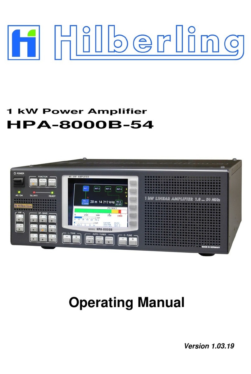
1 kW Power Amplifier
HPA-8000B
Operating Manual
Version 1.04.01

Copyright-notice to the ring binder title
All picture rights reserved by: Bundeswehr / PIZ Marine, DGzRS and Hilberling GmbH

HPA-8000B Operating Manual v1.04.01 3
1 kW Power Amplifier
Hilberling HPA-8000B
Operating Manual
HPA-8000B
developed and manufactured in the EU
by
Hilberling GmbH
Heinrich-Hertz-Strasse 2
24790 Schacht-Audorf
Germany
Logo and name of Hilberling GmbH are registered trademarks
Distribution of the complete document is desired
However, each partial copy or distribution is prohibited
Errors and changes excepted

4
TABLE OF CONTENT
List of Figures............................................................................................................................................. 6
List of Tables .............................................................................................................................................. 8
1About this Manual .................................................................................................................................... 10
2Important Notes ...................................................................................................................................... 11
2.1 General Precautions.........................................................................................................................11
2.2 Notes on Placing..............................................................................................................................12
3Scope of Delivery ..................................................................................................................................... 13
3.1 Data Cables ....................................................................................................................................13
3.2 Operating Manual and Software/Documentation CD-ROM....................................................................13
4Connectors on Rear Panel........................................................................................................................ 14
4.1 Connectors and Controls ..................................................................................................................14
4.2 Pin Assignment J1 to J4 (D-Sub) .......................................................................................................15
5Operating and Display Elements ............................................................................................................. 16
5.1 Overview ........................................................................................................................................16
5.2 TFT Display.....................................................................................................................................17
5.3 Softkeys on Default Screen...............................................................................................................17
5.4 Softkey Menu ..................................................................................................................................18
5.4.1 Display of Device Status SYSTEM INFORMATION .............................................................................19
5.4.1.1 Update Operating Software ..............................................................................................................20
5.4.2 Device Configuration TRX SETUP ....................................................................................................21
5.4.3 Brightness of Display DIM ..............................................................................................................22
6Installation / Initial Operation................................................................................................................ 23
6.1 Cable Connections ...........................................................................................................................23
6.2 Power-on........................................................................................................................................23
7Transceiver Set up ................................................................................................................................... 24
7.1 Select Transceiver Connector............................................................................................................24
7.2 Allocate Transceiver Model ...............................................................................................................24
7.3 Input Power Adjustment ..................................................................................................................26
8Antenna Setup.......................................................................................................................................... 27
8.1 Antenna Allocation to Bands .............................................................................................................27
8.2 Antenna and Antenna Tuner –basic Considerations............................................................................29
8.3 Antenna Tuner ................................................................................................................................29
8.4 Automatic Antenna Tuning ...............................................................................................................31
8.4.1 Error Messages when Tuning Process was aborted .............................................................................33
8.5 Manual Antenna Tuning ...................................................................................................................34
8.5.1 Manual L Tuning..............................................................................................................................36
8.5.2 Manual C Tuning .............................................................................................................................36
8.5.3 Manual CC Tuning ...........................................................................................................................36
9Internal Final PA OPERATE .................................................................................................................... 37
9.1 Error Messages when Final PA was deactivated. .................................................................................37
9.2 ALC Connection ...............................................................................................................................38
Appendix................................................................................................................................................... 39
A1 Software Update and Update Program (for Windows ®) –German .................................................... 41
A1.1 Preliminary Note..............................................................................................................................41
A1.2 Requirements..................................................................................................................................41
A1.3 Update Installation Program and Operating Software..........................................................................41
A1.4 How to Install the Update Program ...................................................................................................42
A1.5 Connect HPA-8000B to PC by USB Data Cable....................................................................................44
A1.6 Set HPA-8000B to Update Readiness .................................................................................................44
A1.7 Start and Setup the Update-Program.................................................................................................45

HPA-8000B Operating Manual v1.04.01 5
A2 Technical Documents............................................................................................................................... 48
A2.1 Technical Data ................................................................................................................................48
A2.2 Amateur Radio Bands ......................................................................................................................49
A2.3 Subbands Antenna Tuning ...............................................................................................................50
A2.4 Switchable L and C Elements Antenna Tuning ....................................................................................55
A2.5 Switch-off Criteria for INPUT OVERLOAD ...........................................................................................55
A2.6 Interface Parameters and Input Power Ranges ..................................................................................56
A3 Customer Information ............................................................................................................................. 57
A3.1 User Information .............................................................................................................................57
A3.1.1 Declaration of Conformity (shortened version) ...................................................................................57
A3.1.2 Note Amateur Radio Operation .........................................................................................................57
A3.2 Warranty Terms .............................................................................................................................. 57
A3.3 Disposal Rules.................................................................................................................................58

6
LIST OF FIGURES
Fig. 2–1: Unfolding bails (front equipment feet)......................................................................................12
Fig. 3–1: Cable D-Sub 9-pin ..................................................................................................................13
Fig. 3–2: Cable D-Sub 25-pin ................................................................................................................13
Fig. 3–3: Manual HPA-8000B................................................................................................................. 13
Fig. 3–4: CD-ROM................................................................................................................................13
Fig. 4–1: Connectors and Controls on Rear Panel.................................................................................... 14
Fig. 5–1: Operating and Display Elements ..............................................................................................16
Fig. 5–2: TFT Display showing Default Screen ........................................................................................17
Fig. 5–3: Softkey Menu ........................................................................................................................ 18
Fig. 5–4: Softkey Menu MENU............................................................................................................... 18
Fig. 5–5: Softkey Menu SYSTEM INFORMATION .....................................................................................19
Fig. 5–6: Screen SYSTEM INFORMATION ............................................................................................... 19
Fig. 5–7: Softkey Menu SOFTWARE UPDATE ..........................................................................................20
Fig. 5–8: Screen SOFTWARE UPDATE ....................................................................................................20
Fig. 5–9: Softkey Menu TRX SETUP .......................................................................................................21
Fig. 5–10: Screen TRX SETUP ............................................................................................................... 21
Fig. 5–11: Softkey Menu DIM................................................................................................................22
Fig. 7–1: Transceiver Connector TRX 1 active / inactive...........................................................................24
Fig. 7–2: Transceiver Connector TRX 1 active / inactive, PT-8000A allocated............................................. 24
Fig. 7–3: Setup Transceiver Connector TRX1 .......................................................................................... 25
Fig. 7–4: Setup Transceiver Connector TRX2 .......................................................................................... 25
Fig. 7–5: Setup Input Power 50 Watt - ‘High’..........................................................................................26
Fig. 7–6: Setup Input Power 100 Milliwatt - ‘mW’....................................................................................26
Fig. 7–7: Setup Input Power 5 Watt - ‘Low’ ............................................................................................ 26
Fig. 7–8: Input Power Meter ‘High’ ........................................................................................................26
Fig. 7–9: Input Power Meter ‘mW’ .........................................................................................................26
Fig. 7–10: Input Power Meter ‘Low’ .......................................................................................................26
Fig. 8–1: Antenna Allocation –Toggle the active Transceiver ...................................................................27
Fig. 8–2: Antenna Allocation –Change of Antenna Connector .................................................................. 28
Fig. 8–3: Antenna Allocation –Factory Setting........................................................................................28
Fig. 8–4: Antenna Allocation –Variation Example.................................................................................... 28
Fig. 8–5: Antenna Tuner activated –Showing Frequency Information....................................................... 30
Fig. 8–6: Antenna Tuner activated –no Frequency Information ............................................................... 30
Fig. 8–7: Auto-Tuning activated „Set PTT On“ ........................................................................................ 31
Fig. 8–8: Auto Tuning –Input Power too low „Tuning Signal low“ ............................................................ 32
Fig. 8–9: Auto Tuning –Input Power too high „Tuning Signal high“..........................................................32
Fig. 8–10: Auto Tuning –Input Power ok „Tuning“ ................................................................................. 32
Fig. 8–11: Auto Tuning finished „Tuning done“ ....................................................................................... 32
Fig. 8–12: Auto-Tuning aborted „Tuning abort“ ......................................................................................33
Fig. 8–13: Auto Tuning –Input Power unstable „Input unstable“ .............................................................33
Fig. 8–14: Auto Tuning –Output Power too high „Output Overload“......................................................... 33
Fig. 8–15: Manual Tuning activated „Set PTT On“ ...................................................................................34
Fig. 8–16: Manual Tuning –Input Power too low „Tuning Signal low“.......................................................35
Fig. 8–17: Manual Tuning –Input Power too high „Tuning Signal high“ ....................................................35
Fig. 8–18: Manual Tuning –Input Power ok „Please Tune“ ......................................................................35
Fig. 8–19: Manual Tuning –Center Capacitance CC ................................................................................ 36
Fig. 9–2: Input Overload ...................................................................................................................... 37
Fig. 9–1: Input Overload 1.................................................................................................................... 37
Fig. 9–3: Output Overload .................................................................................................................... 38
Fig. 9–4: Ouput Overload Mid ...............................................................................................................38
Fig. 9–5: Ouput Overload High..............................................................................................................38
Fig. 9–6: Current Overload ................................................................................................................... 38
Fig. A1–1: Setup –Select Language ...................................................................................................... 42
Fig. A1–2: Setup –Close Other Applications ...........................................................................................42
Fig. A1–3: Setup –Select Target Folder .................................................................................................42
Fig. A1–4: Setup –Select Start Menu Folder...........................................................................................43

HPA-8000B Operating Manual v1.04.01 7
Fig. A1–5: Setup –Select Additional Tasks ............................................................................................. 43
Fig. A1–6: Setup –Summary / Ready for Installation .............................................................................. 43
Fig. A1–7: Setup –Installation Completed / Exit Setup Assistant .............................................................. 44
Fig. A1–8: Setup –Cancel Installation / Exit Setup.................................................................................. 44
Fig. A1–9: Screen BOOTLOADER........................................................................................................... 45
Fig. A1–10: Software Update –Auswahl COM-Port.................................................................................. 45
Fig. A1–11: Software Update –COM-Port nicht nutzbar........................................................................... 46
Fig. A1–12: Software Update –Auswahl Betriebssoftware ....................................................................... 46
Fig. A1–13: Software Update –Update-Vorgang..................................................................................... 47
Fig. A1–14: Software Update –Software ist nicht aktueller ...................................................................... 47
Fig. A1–15: Software Update –Update-Vorgang abgebrochen ................................................................. 47

8
LIST OF TABLES
Tab. 3–1: Scope of Delivery..................................................................................................................13
Tab. 4–1: Connectors on Rear Panel......................................................................................................14
Tab. 4–1: Connectors on Rear Panel (continued) .................................................................................... 15
Tab. 4–2: Pin Assignment D-Sub ........................................................................................................... 15
Tab. 5–1: Operating and Display Elements .............................................................................................16
Tab. A2-1: Technical Data ....................................................................................................................48
Tab. A2–2: Frequency Bands HF ........................................................................................................... 49
Tab. A2–3: Frequency Bands VHF ......................................................................................................... 49
Tab. A2–4: Subbands 160m.................................................................................................................. 50
Tab. A2–5: Subbands 80m.................................................................................................................... 51
Tab. A2–6: Subbands 40m.................................................................................................................... 52
Tab. A2–7: Subbands 30m.................................................................................................................... 52
Tab. A2–8: Subbands 20m.................................................................................................................... 53
Tab. A2–9: Subbands 17m.................................................................................................................... 53
Tab. A2–10: Subbands 15m.................................................................................................................. 54
Tab. A2–11: Subbands 12m.................................................................................................................. 54
Tab. A2–12: Subbands 10m.................................................................................................................. 55
Tab. A2–13: Switchable Inductances und Capacitances Harmonic Filter .................................................... 55
Tab. A2–14: Switch-off Criteria for Input Overload..................................................................................55
Tab. A2–15: Interface Parameters.........................................................................................................56
Tab. A2–16: Input Power Ranges ..........................................................................................................56

HPA-8000B Operating Manual v1.04.01 9

10
1 ABOUT THIS MANUAL
In this manual the following signs and symbols are used:
The STOP sign indicates a warning that must be obeyed for safety reasons.
This sign indicates an important explanation or a specific advice which should be obeyed.
An additional information or explanation is indicated this way.
Copyright © 2016-2018 by Hilberling GmbH

HPA-8000B Operating Manual v1.04.01 11
2 IMPORTANT NOTES
Read and save this Operating Manual carefully before attempting to operate the device. This manual contains
important safety and operating instructions to prevent damages caused by faulty operation.
2.1 General Precautions
WARNING HIGH VOLTAGE !
Do not touch antenna, antenna cable or antenna plugs and sockets during transmission. This may result in
an electrical shock or burn of your skin by high-frequency.
WARNING !
The plug of the 230V power cord represents the designated separation device of the amplifier from the
mains according to standard. The socket must be placed near the amplifier and easily accessible. The
power cord must be able easily disconnected from mains.
CAUTION !
Make sure that no objects may penetrate into device or will touch connectors on rear panel of the power
amplifier. This could cause electrical shock and severe injury.
PROTECT the amplifier from precipitation like rain or any liquid. Do not operate the power amplifier in
excessively dusty or very humid environment.
PROTECT the amplifier from operation by any unauthorized person notably children.
AVOID placing and using the power amplifier in areas with temperatures below -15°C or above +50°C.
If the environment temperature drops so low that the dew point is undercut, avoid operating before the
devices are dried completely.
AVOID placing the power amplifier against a wall. This may inhibit proper air circulation and could cause
overheat. Do not cover any air inlets and outlets at front, bottom and rear panel of the device.

12
2.2 Notes on Placing
When selecting the place for operating the HPA-8000B bear in mind the general limitation
concerning environmental conditions as outlined in the specifications and the cautions at the very
beginning of this manual (see section 2.1).
Always handle the HPA-8000B with care –consider the weight of ca. 20 kg (ca. 50 lbs).
Please make sure proper air circulation. Do not cover any air inlets and outlets at front, bottom and
rear panel of the device.
Choose the place of installation so that all connectors of the HPA-8000B are reachable at any time,
this is especially true for the supply cable connector.
Select a power outlet that is capable to handle the power requirements. Connect your HPA-8000B to
a proper ground system. In addition, observe the relevant technical electrical regulations and the
local regulations of the power supplier. A good grounding system not only prevents electrical shock
but also helps to ensure trouble free operation and will diminish television and broadcast
interference (TVI/BCI).
For your convenience you might raise the front of HPA-8000B by unfolding and locking tilt bails mounted at the front
equipment feet into front position as shown on Fig. 2–1.
If a large resistance will complicate the unfolding, please easily spread the bail for hurdle the locking
nib to avoid damage of the equipment foot.
Fig. 2–1: Unfolding bails (front equipment feet)

HPA-8000B Operating Manual v1.04.01 13
3 SCOPE OF DELIVERY
Examine your HPA-8000B for signs of damage during shipping. Should any damage be apparent please take
appropriate measures (contacting your carrier). We recommend to retain all packing material –it might be used for
shipment of the power amplifier in the future. It is specially made for the HPA-8000B.
Listed below the hardware and all accessories delivered with your HPA-8000B. Make sure you have received and
unpacked everything:
Tab. 3–1: Scope of Delivery
Quantity
Description
Fig.
1
D-Sub 9-pin (HPA-8000B ⬄PT-8000A)
3–1
1
D-Sub 25-pin (HPA-8000B ⬄PT-8000A)
3–2
1
Operating Manual
3–3
1
Software CD-ROM
• HPA-8000B Update Software (Windows®)
• Operating Manual (PDF)
3–4
3.1 Data Cables
Fig. 3–1: Cable D-Sub 9-pin
Data Cable (HPA-8000B ⬄PT-8000A)
Length approx. 2.0 m
Fig. 3–2: Cable D-Sub 25-pin
Data Cable (HPA-8000B ⬄PT-8000A)
Length approx. 1.8 m
3.2 Operating Manual and Software/Documentation CD-ROM
Fig. 3–3: Manual HPA-8000B
Fig. 3–4: CD-ROM

14
4 CONNECTORS ON REAR PANEL
This section introduces the connectors on the rear panel of the HPA-8000B.
4.1 Connectors and Controls
Fig. 4–1: Connectors and Controls on Rear Panel
Tab. 4–1: Connectors on Rear Panel
No
Label
Type
Description
E
Threaded Bolt
M6
Grounding connector for station ground
FUSE
AC FUSE
Thermal Fuse
16 A time-lag
Thermal circuit breaker, 230 V AC, resettable
J1
AUX
TRX 1
DE-9
(D-Sub 9-pin)
Output / input signals for transceiver 1 (Wiring Tab. 4–2)
J2
AUX
TRX 2
DE-9
(D-Sub 9-pin)
Output / input signals for transceiver 2 (Wiring Tab. 4–2)
J3
REMOTE
TRX 1
DB-25
(D-Sub 25-pin)
Output / input signals for transceiver 1 (Wiring Tab. 4–2)
J4
REMOTE
TRX 2
DB-25
(D-Sub 25-pin)
Output / input signals for transceiver 2 (Wiring Tab. 4–2)
J5
PTT
TRX 1
RCA
HF PTT transceiver 1 +5 V / GND (GND = TX)
J6
PTT
TRX 2
RCA
HF PTT transceiver 2 +5 V / GND (GND = TX)
J7
ALC
TRX 1
RCA
ALC output transceiver 1; adjustable by PJ7
J8
ALC
TRX 2
RCA
ALC output transceiver 2 ; adjustable by PJ8
J9
REMOTE PC
USB-B
Input / output data (USB Cable)
1. Interface to PC for HPA-8000B remote operation (CAT)
2. Interface to PC for update the software on HPA-8000B
J10
VHF
TRX 1
N
VHF input transceiver 1
only for TRX PT-8000A
50 / 70 MHz TRX PT-8000A only
‘CAT Type’ selection: ‘Hilberling’ (Sec. 5.4.2 and 7.2). *
J11
TRX 1
N
Input transceiver 1
1.8 … 29.7 MHz
TRX PT-8000A
1.8 … 29.7 / 50 / 70 MHz
TRX by other manufacturer
J5
J8
J6
J7
J14
J15
J18
J16
J17
E
J1
J2
J3
J4
J10
J11
J9
J12
J13
FUSE
PJ8
PJ7

HPA-8000B Operating Manual v1.04.01 15
Tab. 4–1: Connectors on Rear Panel (continued)
No.
Label
Type
Description
J12
VHF
TRX 2
N
VHF input transceiver 2
only for TRX PT-8000A
50 / 70 MHz TRX PT-8000A only
‘CAT Type’selection: ‘Hilberling’ (Sec. 5.4.2 and 7.2). *
J13
TRX 2
N
Input transceiver 2
1.8 … 29.7 MHz
TRX PT-8000A
1.8 … 29.7 / 50 / 70 MHz
TRX by other manufacturer
J14
ANT. 4
N
HF output antenna 4
J15
ANT. 3
N
HF output antenna 3
J16
ANT. 2
N
HF output antenna 2
J17
ANT. 1
N
HF output antenna 1
J18
PREDISTORSION
-60dBc ATT. PA OUT
SMA
HF Output, attenuated by 60 dB , e.g. for predistorsion on TRX
PJ7
ALC adj.
TRX 1
Trim Pot
Adjustment of ALC output on transceiver 1 within range 0 … −10 V
at RCA J7 and D-Sub J1 Pin 6
PJ8
ALC adj.
TRX 2
Trim Pot
Adjustment of ALC output on transceiver 2 within range 0 … −10 V
at RCA J8 and D-Sub J2 Pin 6
*Inputs J10 and J12 are only usable for a connection to the Hilberling PT-8000A Transceiver.
If so select option ‘Hilberling’as a ‘CAT Type’at the TRX Setup (see Section 5.4.2 and 7.2).
4.2 Pin Assignment J1 to J4 (D-Sub)
Tab. 4–2: Pin Assignment D-Sub
No.
Label
Figure
Pin Assignment
J1
AUX
TRX 1
1HF-PTT TRX 1 +5V (GND=TX) 6ALC OUT
(
0 … −10 V
)
*
2<not connected> 7GND
3< not connected > 8< not connected >
4VHF-PTT TRX 1 +5V (GND=TX) 9TX INHIBIT (GND=TX)
5GND
*adjustable by PJ7
J2
AUX
TRX 2
as J1
Assignment analogous to J1
Pin 6ALC OUT adjustable by PJ8
J3
REMOTE
TRX 1
1GND 14 < not connected >
2< not connected > 15 Bit A of Band Data
3Bit B of Band Data 16 Bit C of Band Data
4Bit D of Band Data 17 GND
5< not connected > 18 < not connected >
6< not connected > 19 GND
7< not connected > 20 < not connected >
8< not connected > 21 < not connected >
9RX TTL for CAT 5V TTL or CI-V 22 TX TTL for CAT 5V TTL
10 Band Data Voltage Input 23 GND
11 GND 24 RS232 RX (CAT)
12 RS232 TX (CAT) 25 GND
13 GND
J4
REMOTE
TRX 2
as J3
Assignment analogous to J3

16
5 OPERATING AND DISPLAY ELEMENTS
Section 5.1 and 5.2 introduce operating and display elements at the front panel. Furthermore section 5.3 describes
the softkey menus and screens for configuration, system information and software update.
5.1 Overview
Tab. 5–1: Operating and Display Elements
Fig. 5–1: Operating and Display Elements
Element
Label
Description
ONOFF
Main Switch
POWER
When power on:
All LEDs –including LEDs assembled to buttons –will light up for approx. 1 second (function test),
LED AC / ON will light up permanently.
LED AC / ON
AC / ON
Lights up when device is powered on and supply voltage of 230 V AC is applied.
LED TX / PTT
TX / PTT
Lights up when the PA is activated (LED READY shine) and the HPA-8000B receives a PTT signal.
LED READY
READY
Lights up when the PA of HPA-8000B was activated by pushing button OPERATE.
When the PA is not activated, transceiver HF signals will be sent without amplification to the currently
switched antenna output connector.
TFT Display
÷
The TFT display shows the relevant operating parameters and at a time the current functions of the
so-called ‘softkeys’ placed right hand side of the display as well.
POWER
ONOFF
TFT Display
Sec. 5.2
Softkeys
Sec. 5.3
LED AC / ON
LED TX / PTT
VHF
Selection
VHF amateur
radio band
6 m / 4 m
(only if no CAT
remote control by
TRX/PC)
Sec. 8.1 3.
HF - BAND
Selection
HF amateur
radio band
(except 60m)
(only if no CAT
remote control
by TRX/PC)
Sec. 8.1 3.
FUNCTION
REMOTE
LED Remote control of
HPA by TRX, Sec. 10.3
MENU
Call-up the softkey menu
Sec. 5.3
OPERATE
Activation of
power amplifier (final PA)
Sec. 9
L - TUNE
–/ +
Manual tuning
Inductances
Sec. 8.5.1
AUTO TUNER
TUNER
Activation of the
tuner, Sec. 8.3
START
Automatic tuning,
Sec. 8.4
MANUAL
Manual tuning
Sec. 8.5
C - TUNE
–/ +
Manual tuning
Capacitances
Sec. 8.5.2
LED READY

HPA-8000B Operating Manual v1.04.01 17
5.2 TFT Display
In default view („default screen“) the TFT display gives a status overview about relevant
operating parameters of the HPA-8000B. These include displaying the active
transceiver with current band and transmission frequency, as well as the antenna
which is allocated to the band, furthermore indication of power, SWR and
temperature, as well as the antenna transceiver configuration of the inactive
transceiver.
Fig. 5–2: TFT Display showing Default Screen
5.3 Softkeys on Default Screen
Right next to the display there are six buttons placed in vertical line as ‘Softkeys’
(buttons with changeable function) to operate the HPA-8000B. They allow to activate
or select functions shown on display as a so-called ‘Softkey Menu’ at right border (see
Sec. 5.4).
Exceptions to this rule –so softkeys without a menu –the following functions are
existing:
Toggle the antenna connector and the active transceiver is directly possible by
using the upper three softkeys on default screen (Sec. 8.1).
Manual tuning the center capacitances of the harmonic filter (CC-Tune) will be
done directly by using the two lower softkeys on default screen (Sec. 8.5.3).
Softkeys
Temperature
PA und CPU
Power Meter
Power Output POUT
SWR Meter
Power Meter
Power Input PIN
TRX Connector 1
(device allocated)
(active)
TX Indicator TRX 1
(HPA air TRX 1)
Antenna 2 / 3 / 4
(inactive)
Transmit Frequency
(active TRX)
Antenna Routing
TRX 2
(inactive)
Amateur Radio Band
(active TRX)
TRX Connector 2
(no device allocated)
(inactive)
Antenna and
TRX Toggle
(by softkeys)
Current Drain
PA
Antenna Routing
TRX 1 (active)
Antenna 1
(active)

18
5.4 Softkey Menu
The six keys (so-called ‘softkeys’) right next to the display give access to the functions
shown on the display as a so-called ‘Softkey Menu’ at right border (exceptions see
Sec. 8.1 and 8.5.3).
When power on the HPA-8000B the softkey menu is removed.
Pushing the button MENU in the cluster FUNCTION will show the softkey menu
MENU (pushing again will remove the menu):
Fig. 5–3: Softkey Menu
Fig. 5–4: Softkey Menu MENU
Remove the softkey menu.
Softkey menu and screen SYSTEM INFORMATION will be called up to show system
information and operating parameters (Sec. 5.4.1).
Softkey menu and screen TRX SETUP will be called up to show and edit device
configuration (Sec. 5.4.2).
Softkey menu DIM will be called up to adjust brightness of display
(Sec. 5.4.3).
Toggles the unit of the temperature indicators for PA and CPU between
degree Celsius (°C) and degree Fahrenheit (°F).
If automatic or manual antenna tuning is activated (Sec. 8.4 u. 8.5) the softkey menu
(MENU) cannot be called up.
Softkeys
Softkey Menu MENU

HPA-8000B Operating Manual v1.04.01 19
5.4.1 Display of Device Status SYSTEM INFORMATION
Pushing softkey SYSTEM Info from softkey menu MENU (Fig. 5–4) will call up softkey
menu and screen SYSTEM INFORMATION:
Fig. 5–5: Softkey Menu SYSTEM INFORMATION
Return to softkey menu MENU (Sec. 5.4) and default screen.
Softkey menu and screen SOFTWARE UPDATE will be called up to update the
operation software (Sec. 5.4.1.1).
System information will be shown on display:
Fig. 5–6: Screen SYSTEM INFORMATION
Temperature PA
Amateur Radio Band
Hardware Revision
Software Version
Serial Number
Input Power
Band Info digital
Current Drain PA
Forward Power
Temperature CPU
Band Info analog
Standing Wave Ratio
IARU Region

20
5.4.1.1 Update Operating Software
Pushing softkey SW Update from softkey menu SYSTEM (Fig. 5–5) will call up softkey
menu and screen SOFTWARE UPDATE:
Fig. 5–7: Softkey Menu SOFTWARE UPDATE
Return to softkey menu SYSTEM und screen SYSTEM INFORMATION (Sec. 5.4.1).
Software update will not be executed.
Return to softkey menu SYSTEM und screen SYSTEM INFORMATION (Sec. 5.4.1).
Software update will be continued.
A new screen will be shown on display (for details, see appendix A1–6).
All entries starting from row 4 will be removed and a security query will be shown
instead:
Fig. 5–8: Screen SOFTWARE UPDATE
Select ESC or NO to end the update procedure.
Select YES to continue the update procedure, see appendix Sec. A1–6.
Hardware Revision
Software Version
Serial Number
Security Query
Table of contents
Other Hilberling Amplifier manuals
Popular Amplifier manuals by other brands

PerkinElmer
PerkinElmer 5184 instruction manual

Clear One
Clear One SLX300 SpeakerLinX Installation and setup guide
tech21
tech21 PW60 owner's manual
EMPHASER
EMPHASER EA-M1 Installation & operating manual

Daniels Electronics Ltd.
Daniels Electronics Ltd. VT-3A130 instruction manual
Elmo
Elmo SSA Series Installation & operating manual
