• Only specifically trained/qualified Technicians (Stoddart, one of our service agents, or a similarly qualified persons) should carry out any
and all repairs, maintenance and services
Carefully read this instruction booklet, as it contains important advice for safe installation, operation and maintenance� Keep this booklet on
hand in a safe place for future reference by other operators or users�
Stoddart design, manufacture & distribute Food Service Equipment (appliances) exclusively for the commercial market.
This appliance is not designed nor intended for household or domestic use & must not be used for this purpose.
This product is intended for commercial use, and in line with Australian electrical safety standards the following warnings are provided:
• This product is not intended for use by persons (including children) with reduced physical, sensory or mental capabilities, or lack of
experience and knowledge, unless they have been given supervision or instruction concerning the use of the product by a person
responsible for their safety� Children should be supervised to ensure that they do not play with the product
• If the supply cord is damaged, it must be replaced by the manufacturer, its service agent or similarly qualified persons in order to avoid
a hazard
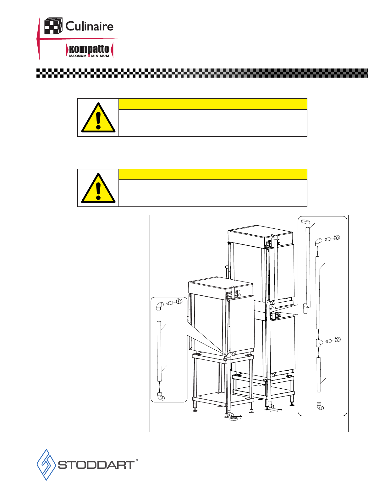
• All units MUST be installed according to the procedures stated in the installation section of this manual
• In the case of new personnel, training is to be provided before operating the equipment
• DO NOT use this unit for any other purpose than its intended use
• DO NOT store explosive substances such as aerosol cans with a flammable propellant in or near this unit
• Keep fingers out of “pinch point” areas
• Unit is not waterproof DO NOT use jet sprays, hoses or pour water over/on the exterior of the unit
• Only use this unit with voltage specified on the rating label
• Do NOT remove any cover panels that may be on the unit
• DO NOT use sharp objects to activate controls
• If any fault is detected, refer to troubleshooting
• The manufacturer declines any liability for damages to persons and/or things due to an improper/wrong and/or unreasonable use of the
machine
When using any electrical unit, safety precautions must always be observed�
Our units have been designed for high performance� Therefore, the unit must be used exclusively for the purpose for which it has been designed�
Read these instructions carefully and retain for future reference�
The manufacturer and distributor cannot be held responsible or liable for any injuries or damages of any kind occurred to persons, units
or others, due to abuse and misuse of this unit in regards to installation, un-installation, operation, servicing or maintenance, or lack of
conformity with the instructions indicated in this documentation�
Disclaimer
All units made by the manufacturer are delivered assembled, where possible, and ready to install� Any installation, un-installation,
servicing, maintenance and access or removal of any parts, panels or safety barriers that is not permitted, does not comply in
accordance to this documentation, or not performed by a TRAINED AND AUTHORISED SPECIALIST will result in the
IMMEDIATE LOSS OF THE WARRANTY�
The manufacturer cannot be held responsible or liable for any unauthorized modifications or repairs� All modifications or repairs must
be approved by the manufacturer in writing before initiating� All modifications or repairs performed to this unit must be performed at all
times by a TRAINED AND AUTHORISED SPECIALIST�
Attention
General Information
Service
Thank you for choosing this quality Culinaire product� All our products are designed and made to meet the needs of food service professionals�
By using, caring and maintaining your Culinaire product according to these instructions, your Culinaire product should give you many years of
reliable service�
Stoddart is a wholly Australian owned company, which manufactures and distributes Culinaire commercial catering equipment�
Stoddart products are manufactured and/or engineered in Australia to provide excellent results whilst offering-value-for-money, ease-of-use
and reliability�
Stoddart manufacture and distribute a comprehensive range of equipment for kitchens, food preparation and presentation�
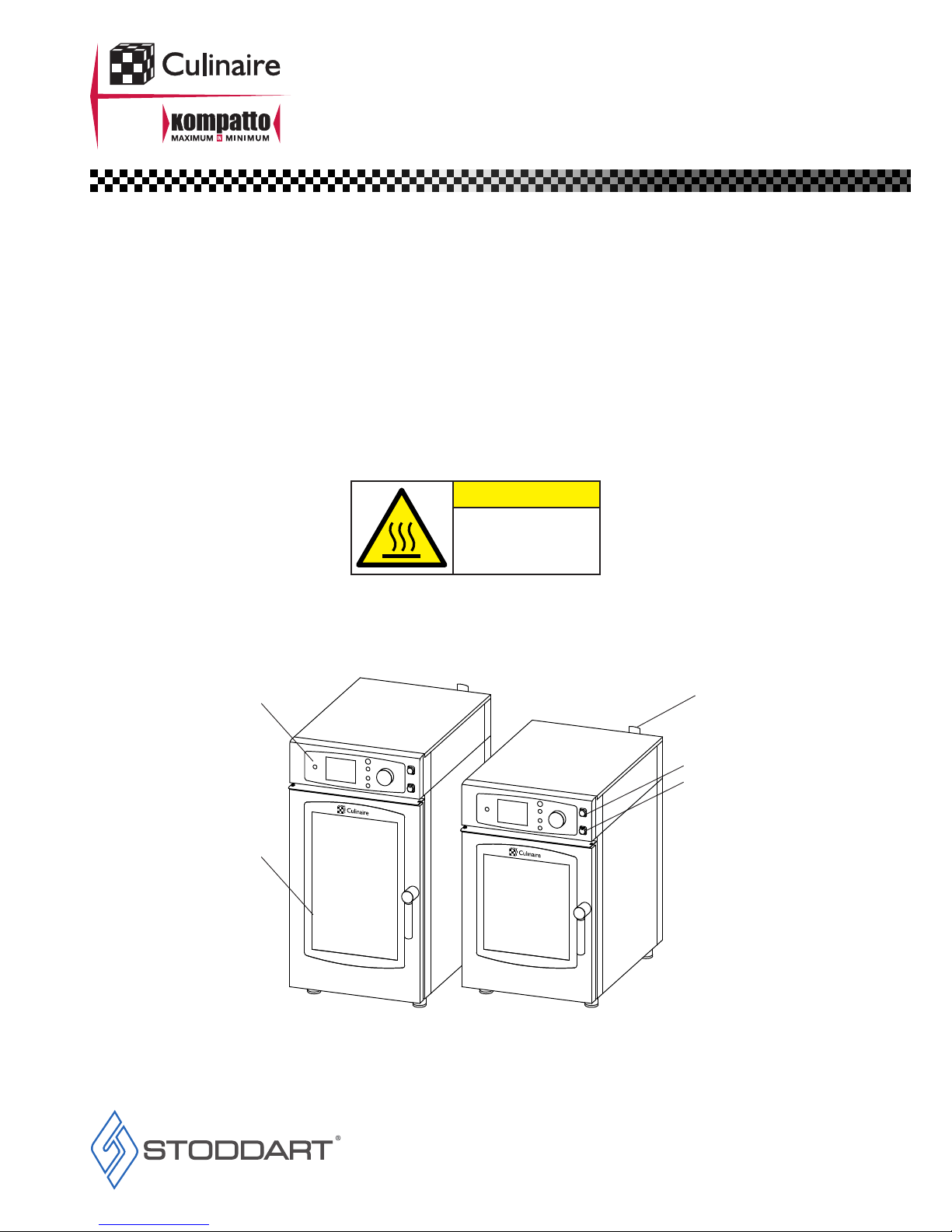
Configuration may vary according to model�