CULITEK CULGR-24-NG User manual

This manual contains important information regarding your Culitek unit. Please read this manual
thoroughly prior to equipment set-up, operation and maintenance. Failure to comply with regular
maintenance guidelines outlined in this manual may void the warranty.
Instruction Manual
RESTAURANT RANGE
CULGR-24-NG/LP, CULGR-36-NG/LP, CULGR-60-NG/LP,
CULGR-3624-NG/LP, CULGR-6024-NG/LP
Natural Gas (/NG) or Liquid Propane (/LP)
Restaurant Ranges
A Professional Line of Commercial Cooking Equipment

±
0.25
±
0.1
±
0.2
±
0.8
±
0.5
±
0.2
°
±
0.3
60.00"
24.00"
60.33"
6.00"
32.67"
35.87"
审核
设计
标记
处数
更改文件号
签名
年 月 日
标准化
批准
第 张
1 2
76
543
8
87
4 53
6
21
F
E
D
C
B
A
共 张
D
C
B
A
A
F
E
版本
比 例
投影
材料
工艺
广州宏展餐饮设备有限公司
1000-2000mm
角度
400-1000mm
120-400mm
30-120mm
6-30mm
0.5-6mm
未注尺寸公差
GB/T1804-2000
物料编码:
三视图
HFSO-60-G24
±
0.25
±
0.1
±
0.2
±
0.8
±
0.5
±
0.2
°
±
0.3
36.00"
60.33"
6.00"
32.67"
35.87"
审核
设计
标记
处数
更改文件号
签名
年 月 日
标准化
批准
第 张
1 2
76
543
8
87
4 53
6
21
F
E
D
C
B
A
共 张
D
C
B
A
A
F
E
版本
比 例
投影
材料
工艺
广州宏展餐饮设备有限公司
1000-2000mm
角度
400-1000mm
120-400mm
30-120mm
6-30mm
0.5-6mm
未注尺寸公差
GB/T1804-2000
物料编码:
三视图
HFSO-36
WARNING
This manual contains important information regarding your unit. Please read this manual
thoroughly prior to equipment set-up, operation and maintenance. Failure to comply with
regular maintenance guidelines outlined in this manual may void the warranty.
If you smell gas, follow the instructions provided by the gas supplier. Do not try to light the
burner; do not use a telephone within close proximity.
FOR YOUR SAFETY
Do not store or use gasoline or other ammable vapors or liquids in the vicinity of this or
any other equipment
WARNING
Improper installation, adjustment, alteration, service or maintenance can cause damage,
injury or death. Read this installation, operating and maintenance instructions thoroughly
before installing or servicing this equipment.
Restaurant Ranges
A Professional Line of Commercial Cooking Equipment

WARNINGS
• Do not touch any hot surfaces
• Do not immerse unit in liquid at any time
• Do not operate unattended
• Do not use this unit for anything other than intended use
• Do not use outdoors
•Always use on a rm, dry and level surface at least 12” from walls or any other obstruction
• Keep children and animals away from unit
• Any incorrect installation, alterations, adjustments and/or improper maintenance can lead to property loss and
injury. All repairs should be done by authorized professionals only.
• If gas odor is detected, shut unit down at main shutoff valve and contact service company
•Do not store or use gasoline or other ammable vapors or liquids in the vicinity of this appliance
• Do not ship or store upside down
• This unit should be stored in a well ventilated area that contains no corrosive gases.
• Do not get this unit wet
• This product is for commercial use only
BEFORE INSTALLATION
• Installation of this device should be operated by professional technicians
•This device is suitable for an area whose altitude is 0-2,000 ft. If it is higher than this altitude, please contact the
manufacturer.
• Installation of this unit should conform to provisions of gas safety, installation and usage
•This device should be kept at a minimum clearance of 4” away from non-combustible objects on both sides and 8”
at the back (e.g. walls, windows etc.). Do not install on a ammable oor or around other combustible objects.
•This item is intended to sit on a solid and level oor
TO INSTALL
1. Level the device with a level gauge. The height can be adjusted by the adjustable feet.
2. The mounting position should be well-ventilated with proper hood exhaust system that will ensure that all the burnt
gases produced during use are completely disposed of.
3. After installation, level the device and keep stable. Do not sway or tilt during operation.
4. A quick-acting gas shut off valve should be installed near the device where it’s easily reached.
5. Make sure you are using the correct gas supply that is specified for this model. If the gas supply is not intended for
this model, do not proceed with installation.
6. All NG models should be 4-5" W/C at the manifold; all LPG models should be 10-11" W/C at the manifold
7. This unit is applicable to low pressure regulating valves only. High pressure regulating valves and medium pressure
regulating valves are not to be used.
8. Check to make sure the connection pipe to the unit has no leaks
9. If the connecting pipe pressure is 10% higher or lower than the rated pressure, please install a pressure regulator.
10. After connecting the appliance to the gas system, check for leaks at joints and pipe fittings; to do so, use soapy
water or a specific leak detector (spray).
11. Check the gas supply pressure after installation.
12. Gas supply pressure can be measured with a liquid-filled pressure gauge (e.g. a U-shaped pressure gauge, minimum
scale division 0.1mbar) or a digital gauge. Procedure as follows:
• Remove the panel and unscrew the screw on the pressure port
• Place the pressure gauge
• Start up the appliance by following the instructions in this owner’s manual
• Check supply pressure
• After the check, remove the pressure gauge
• Replace the sealing screw
Restaurant Ranges
A Professional Line of Commercial Cooking Equipment

CODES AND STANDARDS
This item must be installed in accordance with:
In the United States:
State and local codes, or in the absence of local codes, with:
National Fuel Gas Code, ANSI-Z223.1/NFPA #54 (latest edition). Copies may be obtained from The American Gas
Association Accredited Standards Committee Z223, @ 400 N. Capital St. NW, Washington, DC 20001 or the Secretary
Standards Council, NFPA, 1 Batterymarch Park Quincy, MA 02169-7471.
NFPA Standard #96 Vapor Removal from Cooking Equipment, latest edition, available from the National Fire Protection
Association, Batterymarch Park, Quincy, MA. In the commonwealth of Massachusetts, all gas appliances vented through
a ventilation hood or exhaust system with a damper or with a power means of exhaust shall comply with 248 CMR.
In Canada:
Local codes:
CAN/CSA-B149.1 Natural Gas Installation (latest edition).
CAN/CSA-B149.2 Propane Installation Code (latest edition), available from the Canadian Gas Association 178 Rexdale
Blvd., Etobicoke, Ontario Canada M9W 1R3.
The installer of this unit should be aware of state, county or local code for connecting this equipment to determine if an
external regulator is required.
PRESSURE REGULATOR:
•All commercial cooking equipment must have a pressure regulator on the incoming gas line for safe and efcient
operation. The regulator provided for this equipment can be used for both natural gas and liquid propane.
•Regulator specications: ¾” NPT inlet and outlet, factory adjusted for 5” WC Natural Gas standard and may be
converted by qualied personnel to be used for Propane at 10” WC.
• Prior to connecting the regulator, check the incoming line pressure. The regulator can only withstand a maximum
pressure of ½ PSI (14” WC). If the line pressure is beyond this limit, a step down the regulator before the regulator
provided will be required. The arrow on the bottom shows gas ow direction and should point downstream to the
equipment.
GAS CONVERSION:
Conversion from Natural Gas to Liquid Propane (LP) or vice versa should only be performed by the factory or an
authorized service agent. In case of troubleshooting, ensure the correct orice sizes of the tips have been provided.
Orice size is marked on the tip.
Burners:
Natural Gas Orice is #39
Liquid Propane Gas Orice is #52
Oven:
Natural Gas Orice is #33
Liquid Propane Gas Orice is #50
Griddle:
Natural Gas Orice is #47
Liquid Propane Gas Orice is #54
Griddle/Broiler:
Natural Gas Orice is #53
Liquid Propane Gas Orice is #57
Restaurant Ranges
A Professional Line of Commercial Cooking Equipment

1. Remove the knobs and front panel.
2. Unscrew bolts and pilot valve, then remove the manifold.
3. Replace the orice ttings into the valve.
4. Install the front panel knobs.
5. Before installing the regulator, unscrew the octagonal cap. If you can read NAT or LP on the plastic insert, ip it over and snap
back in place. It should now read either LP or NAT depending on which you are converting.
OPERATING INSTRUCTIONS AND CONTROLS
When turning on for the rst time please be advised that it might take a little longer to ignite due to the air existing in the pipe. If
the ignition does not light, turn off the ignition switch and wait 3 minutes to try again.
LIGHTING THE PILOT
The manifold units are equipped with standing pilots and each should be lit immediately after the gas is supplied to the
equipment.
6. Before attempting to light the pilots, turn off the main gas valve to the equipment and wait 5 minutes to clear the gas.
7. Turn all gas control knobs to the off position.
8. Turn on control valve and light all pilots.
9. The pilot burner must be lit at the end of the tube. Hold an ignition source through the pilot light hole in the front panel at
the pilot tube. When the ame ignites remove ignition source.
10. Turn off the main gas valve to shut down the equipment.
NOTE: Smoke appearing on initial use of the equipment is normal. This is a result of the anti-rust coating burning off. Allow the
equipment to “burn in” for at least 15 minutes before the rst use.
PILOT FLAME ADJUSTMENT:
The pilot ame on the equipment has been factory adjusted. When adjustment is necessary, adjust the pilot ames as small as
possible but high enough to light the burner immediately when the burner valve is turned to the highest setting. Access to the pilot
ame adjustment screw is obtained by removing the front panel.
BURNERS:
1. Connect the gas supply and ignite the pilot ame with a lighter. If the unit hasn’t been used in a while or if this is the rst
lighting, ignition might take a little longer (about two or three minutes).
2. Press the corresponding valve knob of burner and turn 90 degrees counterclockwise.
3. When nished turn off main burner by rotating the knob clockwise to off position.
BURNER ADJUSTMENT:
Remove the front panel to gain access. Turn burner valve knob to highest setting. Slowly decrease mixing ring aperture to give a
soft blue ame with luminous tips. Then slowly increase opening to a point where the yellow tips disappear and a hard blue ame
is obtained.
±
0.25
±
0.1
±
0.2
±
0.8
±
0.5
±
0.2
°
±
0.3
36.00"
60.33"
6.00"
32.67"
35.87"
审核
设计
标记
处数
更改文件号
签名
年 月 日
标准化
批准
第 张
1 2
76
543
8
87
4 53
6
21
F
E
D
C
B
A
共 张
D
C
B
A
A
F
E
版本
比 例
投影
材料
工艺
广州宏展餐饮设备有限公司
1000-2000mm
角度
400-1000mm
120-400mm
30-120mm
6-30mm
0.5-6mm
未注尺寸公差
GB/T1804-2000
物料编码:
三视图
HFSO-36
±
0.25
±
0.1
±
0.2
±
0.8
±
0.5
±
0.2
°
±
0.3
60.00"
24.00"
60.33"
6.00"
32.67"
35.87"
审核
设计
标记
处数
更改文件号
签名
年 月 日
标准化
批准
第 张
1 2
76
543
8
87
4 53
6
21
F
E
D
C
B
A
共 张
D
C
B
A
A
F
E
版本
比 例
投影
材料
工艺
广州宏展餐饮设备有限公司
1000-2000mm
角度
400-1000mm
120-400mm
30-120mm
6-30mm
0.5-6mm
未注尺寸公差
GB/T1804-2000
物料编码:
三视图
HFSO-60-G24
±
0.25
±
0.1
±
0.2
±
0.8
±
0.5
±
0.2
°
±
0.3
60.00"
60.33"
6.00"
6.42"
32.67"
35.87"
40.82"
审核
设计
标记
处数
更改文件号
签名
年 月 日
标准化
批准
第 张
1 2
76
543
8
87
4 53
6
21
F
E
D
C
B
A
共 张
D
C
B
A
A
F
E
版本
比 例
投影
材料
工艺
广州宏展餐饮设备有限公司
1000-2000mm
角度
400-1000mm
120-400mm
30-120mm
6-30mm
0.5-6mm
未注尺寸公差
GB/T1804-2000
物料编码:
三视图
HFSO-60-GS24
Restaurant Ranges
A Professional Line of Commercial Cooking Equipment

OVEN(S):
Before using the oven, please clean the oven chamber completely. Remove all the packing materials and lm from shipping.
The oven temperature ranges from 250°and 550°.
To turn off the burner: Rotate the knob clockwise to strip mark and align with the salient point.
Note:If the gas type needs to be changed from NG to LPG,the nozzles of main burner and pilot ame should be replaced.
•Before cleaning the stainless steel accessories, please make sure that the used detergent contains no corrosive substance
and is okay for stainless steel surface cleaning. Then dry with a clean cloth.
•When rst using the oven, a unpleasant smell will most likely appear. (Make sure that the smell is not caused by gas
leakage). This smell is produced by overheating of the insulating material and oil residue during the heating process of the
metal. Before rst use, set the temperature to 550°F and heat untill the smell is gone.
•When rst using, the duration of ignition may be a little longer due to the air existing in the new pipe. It cannot be ignited
until all the air is exhausted.
•During ignition,please open the lid under the door and press down the knob and rotate 90°clockwise, align with the salient
point and press down. Ignite the pilot ame with a lighter or match via the ignition hole.
•After the pilot ame is ignited,press the knob for more than 20 seconds to heat up the thermocouple.If the ignition is out
when you loosen the knob,repeat this operation.
• Keep rotating the temperature control knob counterclockwise to ignite the main burner of the oven. Select the appropriate
temperature according to the food requirements.
SEASONING THE GRIDDLE:
1. Pre-heat the griddle surface to 375ºF.
2. Spread a light lm of cooking oil over the entire griddle surface.
3. Allow the oil lm to cook in for approximately 2 minutes, or until it starts smoking.
4. Wipe the griddle surface with a clean damp cloth until all of the oil is removed.
5. For new griddles, repeat this procedure 2-3 times until the griddle has a slick, clean surface.
CLEANING - NOTE: It is important to clean and maintain the unit daily. Checking the unit daily can help avoid serious
accidents. Stop using if there are problems with the unit. Check the condition of the unit before and after using.
Before using: Is the machine tilted?
Is the control panel damaged?
During use: Is there a strange smell or noise?
Is the ame color normal?
Any light back or ameout?
1. Before cleaning, please turn off all gas valves.
2. It is important to clean the burners and drip tray(s) regularly.
3. Clean the stainless steel surface with warm soapy water daily and rinse it dry. During cleaning, do not clean the stainless
steel surface with abrasive detergent, brush or scraper etc. The residual iron scale may cause rusting.
4. Do not clean the surface with a chlorine cleanser (bleach, hydrochloric acid etc.). Do not clean the oor where the unit is
installed with corrosive substances (e.g. KCL).
5. Clean off the dirt and debris on the burners and bafe regularly.
6. Do not modify the ventilation volume needed during combustion.
7. Accumulation of the iron substance (e.g. Material that formed by iron rust dissolving in water in the pipe, especially when
the device is not used for a long time.). Therefore, to avoid accumulation of such substance, clean the food swill that is dif-
cult to clean with stainless steel scraper or a brush containing no iron substances instead of steel brush.
8. Keep substances containing acidic ingredients (vinegar, lemon juice, spices, salt, etc.) away from the stainless steel
components. Acidic vapor from these solutions will damage the surface of the device.
9. A complete cleaning every day will ensure good usage and extend the life of the unit. Clean the unit with a wet towel con-
taining suds or a detergent, rinse it with water and dry it with a clean cloth. Do not clean the device with steel brush, which
may cause rust. Keep parts that are made of iron dry or will rust.
10. Cleaning the stainless steel surface: grease stains can be wiped away with sponge.
11. To avoid rusting of the unit, please make sure that the residual salt inside or outside the device is cleared away.
12. After cleaning, to avoid short-time incomplete combustion, the re hole of the burner should be clear.
13. Turn off the main gas valve if item is not going to be used for an extended period of time.
14. If item is not going to be used for an extended period of time, it is best to clean fully and store in a well ventilated area.
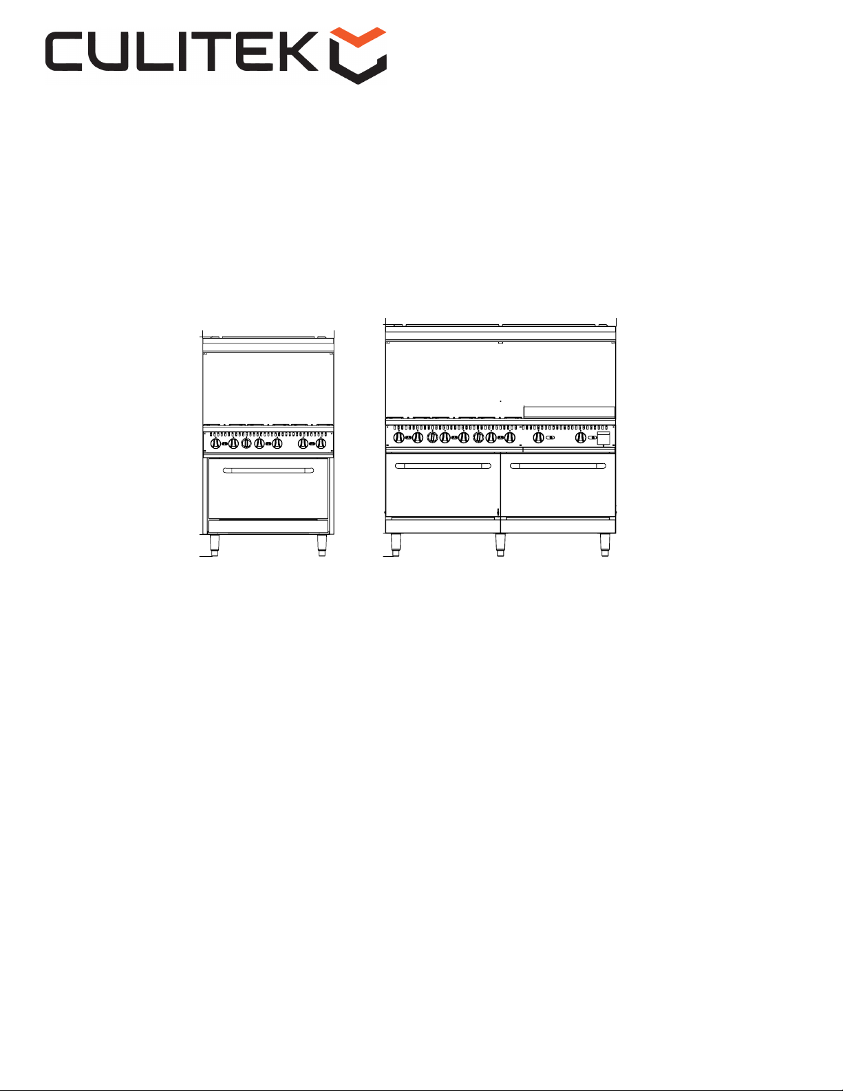
Restaurant Ranges
A Professional Line of Commercial Cooking Equipment

Problem Possible Causes Solution
The pilot ame can’t be ignited
The gas pressure is too low Adjust the relieve valve to
increase pressure
The nozzle is clogged Unclog the nozzle
The gas control valve is
malfunctioning Replace the gas control valve
Problem Possible Causes Solution
The pilot ame is on but the main
burner can’t be ignited
The gas pressure is too low Adjust the relieve valve to
increase pressure
The main burner nozzle is clogged Unclog the nozzle
The gas control valve is defective Replace the gas control valve
Problem Possible Causes Solution
It has a light-back sound when the
gas supply is turned off
Wrong orice size for the gas supply Install proper orice
The damper is too open Adjust the damper
The gas pressure is too low Adjust the relieve valve
Gas pressure too low Increase the gas pressure
Problem Possible Causes Solution
It has a red ame and black smoke
Wrong orice size for the gas supply Install proper orice
The damper is too closed Adjust the damper
Running out of gas/propane Replace tank/increase gas
High elevation Install proper tips for elevation
Bad air/gas mixture Increase air ow/gas to the unit
TROUBLESHOOTING
Before requesting any service on the unit, please check the following chart. Service calls resulting
from lack of maintenance or misuse is not covered under the warranty and may also void the warranty.
Please note that this guide serves only as a reference for solutions to common problems.
Restaurant Ranges
A Professional Line of Commercial Cooking Equipment

CULGR-24-NG/LP
24” Gas Range, 4 Burner
Restaurant Ranges
A Professional Line of Commercial Cooking Equipment

Diagram Number Part Description Quantity
1 Backsplash assembly 1
2Guiding rail groove 2
3 Flue box assembly ,oven 1
4 Inlet pipe 1
5 Gas valve,open top burner 4
6 Thermostat valve,oven 1
7Orice,NG or LP ,open top 4
8Pilot valve 2
9Oven chamber assembly 1
10 Side panel,right 1
11 Door hinge base 2
12 Burner,oven 1
13 Thermocouple,oven 1
14 Leg installation board 4
15 Adjustable leg 4
16 Orice,NG or LP ,oven 1
17 Elbow for oven orice 1
18 Door hinge,right 1
19 Outside panel,oven door 1
20 Lower lid 1
21 Door handle 1
22 Pilot assembly,NG or LP,oven 1
23 Door hinge,left 1
24 Bottom plate,oven 1
25 Lower lid support assembly 2
26 Grid holder 4
27 Oven grid 2
28 Side panel,left 1
29 Knob,oven 1
30 Knob,open top 4
31 Crumb tray assembly 1
32 Front panel 1
33 Ledge 1
34 Insulation board 1
35 Bruner assembly,short 2
36 Burner assembly,long 2
37 Grate 4
CULGR-24-NG/LP
24” Gas Range, 4 Burner
Restaurant Ranges
A Professional Line of Commercial Cooking Equipment

CULGR-36-NG/LP
36” Gas Range, 6 Burner
Restaurant Ranges
A Professional Line of Commercial Cooking Equipment

Diagram Number Part Description Quantity
1 Backsplash assembly 1
2Guiding rail groove 2
3 Flue assembly,oven 1
4 Inlet pipe 1
5 Gas valve,open top burner 6
6 Pilot valve 3
7 Thermostat valve,oven 1
8 Orice,NG or LP,open top 6
9Oven chamber assembly 1
10 Side panel,right 1
11 Door hinge base 2
12 Burner,oven 1
13 Leg Installation board 4
14 Adjustable leg 4
15 Orice,NG or LP,oven 1
16 Elbow for nozzle,oven 1
17 Thermocouple 1
18 Door hinge,right 1
19 Oven pilot assembly,NG or LP 1
20 Lower lid 1
21 Outside panel,oven door 1
22 Door handle 1
23 Door hinge,left 1
24 Lower lid support 2
25 Bottom plate,oven 1
26 Grid holder 4
27 Oven grid 2
28 Side panel,left 1
29 Crumb tray assembly 1
30 Knob,oven 1
31 Knob,open top 6
32 Front panel 1
33 Ledge 1
34 Insulation board 1
35 Bruner assembly,short 3
36 Burner assembly,long 3
37 Grate 6
CULGR-36-NG/LP
36” Gas Range, 6 Burner
Restaurant Ranges
A Professional Line of Commercial Cooking Equipment

CULGR-60-NG/LP
60” Gas Range, 10 Burner
Restaurant Ranges
A Professional Line of Commercial Cooking Equipment

Diagram Number Part Description Quantity
1 Backsplash assembly 1
2 oven ue assembly 2
3 Guiding rail groove 3
4 Inlet gas pipe 1
5 Gas valve,open top 10
6 Pilot valve 5
7 Thermostat valve 2
8 Orice,NG or LP,open top 10
9 Side panel,right 1
10 Door hinge base 4
11 Crumb tray assembly,24" 1
12 Oven grid 4
13 Leg installation board 6
14 Adjustable leg 6
15 Burner,oven 2
16 Oven pilot assembly,NG or LP 2
17 Door hinge,right 2
18 Orice,NG or LP,oven 2
19 Elbow for oven orice 2
20 Thermocouple 2
21 Lower lid 2
22 Outside panel,oven door 2
23 Door handle 2
24 Door hinge,left 2
25 Lower lid support 4
26 Bottom plate,oven 2
27 Grid holder 8
28 Crumb tray assembly,36" 1
29 Knob,oven 2
30 Knob,open top 10
31 Side panel,left 1
32 Front panel 1
33 Ledge 1
34 Insulation board 2
35 Bruner assembly,short 5
36 Burner asembly,long 5
37 Grate 10
CULGR-60-NG/LP
60” Gas Range, 10 Burner
Restaurant Ranges
A Professional Line of Commercial Cooking Equipment

CULGR-3624-NG/LP
36” Gas Range/Griddle Combo, 2 Burner, 24”Griddle
Restaurant Ranges
A Professional Line of Commercial Cooking Equipment

CULGR-3624-NG/LP
36” Gas Range/Griddle Combo, 2 Burner, 24”Griddle
Diagram Number Part Description Quantity
1 Backsplash assembly 1
2Flue box(right) 1
3 Flue box(left) 1
4 Flue assembly,oven 1
5 Guiding rail groove 2
6 Side panel,right 1
7 Inlet gas pipe 1
8Gas valve 4
9 Pilot valve,open top 1
10 Orice,NG or LP,open top 2
11 Thermostat valve,oven 1
12 Orice,NG or LP,griddle 2
13 Pilot valve,griddle 2
14 Door hinge base 2
15 Installation board leg 4
16 Adjustable leg 4
17 Burner,oven 1
18 Orice,NG or LP,oven 1
19 Elbow for oven orice 1
20 Oven pilot assembly,NG or LP 1
21 Door hinge,right 1
22 Thermocouple 1
23 Lower lid 1
24 Outside panel,oven door 1
25 Door handle 1
26 Door hinge,left 1
27 Lower lid support 2
28 Bottom plate,oven 1
29 Oven grid 2
30 Grid holder 4
31 Crumb tray,griddle 1
32 Crumb tray,open top 1
33 Knob,open top 2
34 Front panel 1
35 Knob,oven 1
36 oil tray assembly 1
37 Ledge 1
38 Side panel,left 1
39 Burner assembly,griddle 2
40 Burner assembly,short 1
41 Burner assembly,long 1
42 Grate 2
43 Griddle plate assembly 1
Restaurant Ranges
A Professional Line of Commercial Cooking Equipment

CULGR-6024-NG/LP
60” Gas Range/Griddle Combo, 6 Burner, 24”Griddle
Restaurant Ranges
A Professional Line of Commercial Cooking Equipment

CULGR-6024-NG/LP
60” Gas Range/Griddle Combo, 6 Burner, 24”Griddle
Diagram Number Part Description Quantity
1 Backsplash assembly 1
2Flue assembly ,oven 2
3 Guiding rail groove 3
4 Flue box(right) 1
5 Flue box(left) 1
6Burner assembly,griddle 2
7 Inlet gas pipe 1
8 Orice,NG or LP,open top 6
9 Pilot valve,open top 3
10 Thermostat valve,oven 2
11 Gas valve 8
12 Orice,NG or LP,griddle 2
13 Pilot valve,griddle 2
14 Side panel,right 1
15 Oil tray assembly 1
16 Door hinge base 4
17 Leg installation board 6
18 Adjustable leg 6
19 Burner,oven 2
20 Orice,NG or LP,oven 2
21 Elbow for oven orice 2
22 Oven pilot assembly,NG or LP 2
23 Thermocouple 2
24 Crumb tray assembly,griddle 1
25 Door hinge,right 2
26 Outside panel,oven door 2
27 Door handle 2
28 Door hinge,left 2
29 Lower lid 2
30 Oven grid 4
31 Bottom plate,oven 2
32 Grid holder 8
33 Crumb tray,36" 1
34 Knob,oven 2
35 Knob,open top 8
36 Front panel 1
37 Side panel,left 1
38 Ledge 1
39 Insulation board 2
40 Burner assembly,short 3
41 Burner assembly,long 3
42 Griddle plate assembly 1
43 Grate 6
Restaurant Ranges
A Professional Line of Commercial Cooking Equipment

CULITEK One Year Limited Warranty
CULITEK warrants its equipment against defects in materials and workmanship, subject to the following conditions:
ONE YEAR WARRANTY
CULITEK Ranges are warranted for one year, effective from the date of purchase by the original owner. A copy of the original receipt or
other proof of purchase is required to obtain warranty coverage. This warranty applies to the original owner only, and is not assignable.
Should any product fail to function in its intended manner under normal use within the limits defined in this warranty, at CULITEK ’s
discretion, such product will be repaired, replaced with a refurbished unit, or replaced with a new unit by CULITEK , after defective unit
has been inspected and defect has been confirmed. CULITEK does not assume any liability for extended delays in replacing any item
beyond its control. This warranty does not apply to rubber and non-metallic synthetic parts that may need to be replaced due to normal
usage, wear or lack of preventative maintenance.
This warranty covers products shipped into the 48 contiguous United States. Warranty coverage on products used in Hawaii, Alaska,
Puerto Rico, and Canada cover parts only.
Equipment installed in/on a food truck or trailer will be limited to a period of 30 days from the original date of purchase.
The following conditions are not covered by warranty:
•Equipment failure relating to improper installation, improper utility connection or supply and problems due to improper ventilation.
•Equipment that has not properly been maintained, damage from improper cleaning, and water damage to controls.
•Equipment that has not been used in an appropriate manner, or has been subject to misuse, neglect, abuse, accident, alteration,
negligence, damage during transit, delivery or installation, re, ood, riot, or act of God.
•Equipment that has the model number or serial number removed or altered.
•Equipment on which the security seal has been broken.
If the equipment has been changed, altered, modified, or repaired without express written permission from CULITEK , then the
manufacturer shall not be liable for any damages to any person or to any property, which may result from the use of this equipment
thereafter.
This equipment is intended for commercial use only and this warranty is void if equipment is used in other than a commercial
application.
“THE FOREGOING WARRANTY IS IN LIEU OF ANY AND ALL WARRANTIES EXPRESSED OR IMPLIED INCLUDING ANY IMPLIED WARRANTY
OF MERCHANTABILTY OR FITNESS FOR PARTICULAR PURPOSES AND CONSTITUTES THE ENTIRE LIABILITY OF CULITEK . IN NO EVENT
DOES THE LIMITED WARRANTY EXTEND BEYOND THE TERMS STATED HEREIN.”
WARRANTY CLAIMS &SERVICE
For all warranty claims please have the model number, serial number and a proof of purchase available.
Phone: 1-800-325-1740
For all online warranty claims please include the model number, serial number and detailed description of the issue.
Please attach a copy of your proof of purchase with your e-mail.
E-Mail: [email protected]
Restaurant Ranges
A Professional Line of Commercial Cooking Equipment
This manual suits for next models
9
Table of contents
Other CULITEK Range manuals
Popular Range manuals by other brands

Frigidaire
Frigidaire FFED3005LWC Use & care guide

Frigidaire
Frigidaire Gas Range use and care manual

Smeg
Smeg A4-5 Instructions for installation and use

Kenmore
Kenmore 790.9654 Series Use & care guide

Kenmore
Kenmore 665.75032 Use & care guide

Lang
Lang R30S-M Installation, operation & maintenance instructions