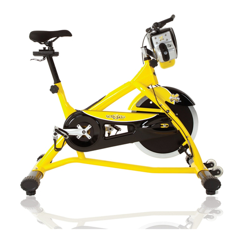
cultsport smartbike c2 User manual


1
SAFETY GUIDELINES
1. It is important to read this entire manual before assembling and using the equipment.
2. Once assembled fully, please inspect to make sure all hardware parts such as bolts, nuts and
washers are positioned correctly and tightly secured.
3.Always inspect the safety chain guard that protects the moving parts of the bike to be in safe and
good order.
4. Always inspect the seat post, seat slider, pedals and handlebar to make sure they are in safe and
stable position before using the bike.
5. It is recommended that you lubricate all moving parts on a monthly basis.
6. To avoid entangling into any moving parts, do not wear loose clothing.
7. Do not remove feet from the pedals while they are in motion.
8. Running or aerobic shoes are required when using the bike.
9. Dry the bike after each use to remove sweat and moisture. Wipe your bike regularly with a mild,
non-abrasive cleaner and water solution. To avoid damaging the finish on the bike, never use a
petroleum-based solvent when cleaning.
10. Please keep children away from the bike while it is in use. Do not allow children to use the bike.
This bike is designed for adults, not children.
11. Do not dismount the bike until the pedals are at a complete STOP.
12. Before starting any exercise program, consult with your physician first. He or she can help
establish the exercise frequency, time and intensity appropriate for your particular age and
condition.
13. If you have any pain or tightness in your chest, an irregular heartbeat, shortness of breath, feel
faint or have any discomfort while you exercise, STOP! Contact your physician before continuing.
14. Do not place fingers or any other objects into moving parts of the exercise equipment.
15. After exercising, please turn the Adjusting Knob to increase tension so the pedals will not rotate
freely and possibly hurt someone while bike is not in use.
16. This equipment is designed for indoor and home use only, not intended for commercial use.
17. The maximum user weight is 110KG, please do not overload.
18. The Console display a variety of functions, it will reflect the corresponding values according to the
different degrees of human movement, Kindly reminder that the heart rate value may not be
accurate, just for your reference.
19. Hold your hand firmly on the fixed handrail (or movable handle) during exercise.
20. Please keep this manual and installation tools properly。
21. Only when the wheel completely stops, then your foot can be out of the pedal strap because of the
large inertance.

2
EXPLODED DRAWING
1
2
3
4
5
78
9
10
11 12
14
13
14
13
15
16
16
17
18
19
20L
20R
21
22
10
21
22
10
23L
23R
24 24
25
25
26
26
27
27
28
29
30
30
31
31
31
31
3233
33
3233
33
34
35
35
36
36
36
37
38
4243
41 4039
40
43
44
4241
39
44
45485147
49
46
50
52
53
54
55
49 49
57
5859
60
5957
58
61
63
64
58
66
67
6270
686962
71L
71R
72
72
73
74
77
76
75
78
80
79
81
81
82
83
84
85
85
87
87
86
88
88
89
89
90
90
90
89
89
89
90
93
92
91
91
90
90 6
94
95
96
97
97
98
98a
98b
96a
97a
97a
65
65
A S6 1PC
C S17-S19 1PC
B S13-14-15 1PC S15
56
56

3
No.
Description
Specification
Qty.
No.
Description
Specification
Qty.
1
Main Frame
1
39
Bolt
M6*12*S10
2
2
Front Stabilizer
1
40
washer
d6*Φ16*1.5
2
3
Handlebar Post
1
41
Bearing bracket
Φ72*11
2
4
Seat Post
1
42
Bearing
6201
2
5
Handlebar
1
43
Fixing plate
t1.5*56*76*Φ30
2
6
Rear Stabilizer
1
44
Screw
M6*10*Φ12
6
7
IPAD Holder
1
45
Idle pulley
Φ42*Φ35*Φ12*24
1
8
Bolt
M8*90*20*S6
1
46
Axle
Φ19*43.5*φ12*19.5
1
9
Ball Cap
S13
1
47
Nut
M10*1*H8*S15
1
10
Washer
d8*Φ16*1.5
5
48
Wave washer
d12*φ17.5*0.3
1
11
Nut
M8*H7.5*S13
1
49
Washer
d12
3
12
Bolt
M10*35
2
50
U Bracket
30*10*1.5
1
13
Washer
d10*Φ20*2
2
51
Bolt
M6*50*Φ12*3
1
14
Nut
M10*H9.5*S17
2
52
Nut
M6*H6*S10
1
15
Console
1
53
Magnet
40*25*5
1
16
Screw
ST4.2*16*Φ8
2
54
Brake pad
60*35*8.0
1
17
Seat
ST4.2*16*Φ8
2
55
Axle
φ12*53.5*47.4
1
18
Washer
d10*Φ30*2.5
1
56
Screw
ST4*19*Φ7
2
19
Knob
M10*Φ58*32
1
57
Washer
d6*φ12*1.2
2
20L
L Nut
1
58
Spring washer
d6
6
20R
R Nut
1
59
Bolt
M6*16*S10
2
21
Blot
M8*20*S6
4
60
Spring
Φ1.5*Φ15*41*N8
1
22
Spring washer
d8
4
61
Axle
Φ17*176*51.5*78
1
23L/R
Pedal
1
62
Bearing
6203
2
24
Bushing
16*2*Φ13*3.5*Φ8
2
63
Belt plate
Φ240*20
1
25
Foam grip
Φ23*3*450
25
64
Bolt
M6*16*S10
4
26
End cap
Φ25*16
26
65
Plug
Φ12*11*Φ3
3
27
Knob
M16*1.5*35*Φ56
27
66
Nut
M6*H6*S10
4
28
Bushing
PT80*40*YPT71*30
28
67
Belt
6PJ560
1
29
Bushing
PT80*40*1.5 70*30
29
68
C ring
d17
1
30
End cap
PT50*25*16
30
69
Wave washer
d17*Φ22*0.3
1
31
End cap
PT80*40*1.5
31
70
Bushing
Φ22*Φ17.1*5.5
1
32
Roller
Φ71*Φ19*24
2
71
Crank L/R
170“L”/ “R”
1
33
Bearing
608ZZ
4
72
Cover
Φ25*7
2
34
Bolt
M6*12*S5
2
73
Tension knob
φ56*34*M8
1
35
Bolt
Φ7.8*30*M6*15*S5
2
74
Nut
M8*H5.5*S14
1
36
Foot pad
Φ52*43*M8
4
75
Brake bolt
φ8*240*M8*25*M6*15
1
PARTS LIST

4
37
Flywheel
6*φ350*36
1
76
Nut
16*16*8*M8
1
38
Axle
24*103*2-Φ12*9.7
1
77
Brake located
16*16*16*φ8.3
1
78
Brake located
16*16*16*φ6.2
1
92
Magnetic Plate
1
79
Nut
M6*H14*S10
1
93
Seat slider
1
80
Nut
M6*H5*S10
2
94
Screw
ST4.2*16*Φ8
1
81
Screw
M5*5*Φ10
4
95
Sensor plate
1
82
Spring
1.2*Φ11.2*135*N29
1
96
Sensor wire
1
83
Cover L
956*718*81
1
97
Handle pulse wire
2
84
Cover R
956*718*81
1
98
Trunk wire
1
85
Cover
φ384*30.5
2
99
Battery
1.5V AAA
2
86
Battery cover
56*31*9.5
1
A
Spanner
S6
1
87
Cover
Φ83*Φ36*11.3
2
B
Spanner
S13-14-15
1
88
Screw
ST4.2*10*Φ8
12
C
Spanner
S17-19、S17
1
89
Screw
ST4.2*16*Φ8
8
90
Screw
ST4.2*10*Φ8
8
91
Nut
M10*1.25*H7.5*S14
2

5
ASSEMBLY INSTRUCTIONS
#21 M8*20*S6 4PCS
#22 d8 4PCS
#10 d8*Φ16*1.5 4PCS
A S6 1PC
1
26
23L 20L
23R
20R
21
22
10
21
22
10
STEP1:
Remove the bolt (21), spring washer (22) and washer (10) from the packing tube using the
spanner(A). Please reserve them for pending step. The packing tube can be discarded. Remove
the bolt(21),spring washer(22)and washer(10) from the rear stabilizer using the
spanner(A).Please reserve them for pending step.
Secure the front stabilizer (2) and rear stabilizer (3) to the main frame (1) with bolt (21),
spring washer (22) and washer (10). Tighten it using the spanner(A).

6
B
S15
23L
71L
20L
23L
C
S19
23R
B
S15
23R
20R
C
S19 B
S15
B
S15
71R
71L 71R
figure A figure B
Attach Left Pedal (23L) to Left Crank (71L). Turn the Left Pedal (23L)counter-clockwise with the hand until it
is tight, then use Spanner (B)to securely tighten. Secure the nut(20L) to left crank with the spanner(C) as
figure A. Attach Right Pedal (23R) to Right Crank(71R). Turn the Right Pedal (23R) clockwise with the
hand until it is tight, then use Spanner (B) to securely tighten. Secure the nut(20R) to right crank with the
spanner(C) as figure B.
Note: The Pedals (23L/R) are marked "L" and "R" for Left and Right. Make sure you attach the correct pedal
to the corresponding crank.

7
14
27
figure A
STEP 2:
Remove the seat post (4) from the main frame (1). Then insert the seat post (4) into the main
frame (1) by turning a direction. Secure the seat post(4) with knob(27) once in the suitable
position show as figure A.
18 d10*Φ30*2.5 1PC
19 M10*Φ58*32 1PC
1
4
18
19
17

8
Secure the seat (17) to the seat post (4) in the main frame (1). Adjust to the suitable position,
then tighten them with washer(18) and knob(19).
1
3
5
12
14
13
14
13
#12 M10*35 2PCS
#13 d10 2PCS
#14 M10*H9.5*S17 2PCS
C S17-S19 1PC
27
98
98b
98a
96a
98b
96a
figure A
STEP 3:
Connect the sensor wire (96) and trunk wire (98), and put the thread end into handlebar post (3).
Then insert the handlebar post(3) into the main frame(1) and secure with knob(27).
Fix the handlebar (5) to the handlebar post (5) in the main frame (1) with bolt (12), washer (13)
and nut (14). Then tighten with the spanner(C).

9
B S13-14-15 1PC S15
16
16
7
8
9
11
10
15
1
3
5
27
#8 M8*90*20*S6 1PC
#9 S13 1PC
#11 M8*H7.5*S13 1PC
#10 d10 1PC
#16 ST4.2*16*Φ8 2PCS
98a
15a
15b
97a
97a
15b
97a
figure b
15a
98a
figure A
STEP 4:
Remove the bolt (8), washer (10) and nut (11) from the handlebar (5) using the spanner (B).
Pass the IPAD holder (7) through the handlebar (5) with bolt (8). Tighten them with washer(16)and
nut(23) using spanner(A).Then put the ball cap(9)cover the nut(11).
Secure the console (15) to the handlebar (5) with screw (16). Tighten it with the
spanner(B).Connect the trunk wire(98) with the console(15)show as figure A. Connect the handle
pulse wire(97) with the console(15) show as figure B.
Assembly is complete!

10
Install or change the battery
99
1
B S13-14-15 1PC S15
15
5
Install the battery:
1. Take out the 2 x AAA batteries for later use.
2. Insert the 2xAAA into the battery holder in the console (15). Pay attention to the negative
and positive electronic before the install.
3. Secure the console (15) to the handlebar (5) in the main frame (1) using spanner(B) same
as the STEP 4.
Change the battery:
1. Remove the trunk wire (98) from the console (15). Remove the handle pulse wire (97) from
the console (15).
2. Remove the screw (16) from the console (1) using the spanner(B). Take out the 2 X AAA from
the battery holder. Then insert the new 2 X AAA into the battery holder. Pay attention
to the negative and positive electronic before the install.
3. Secure the console (15) to the handlebar (5) in the main frame (1) using spanner(B) same
as the STEP 4.
Attention:
The two batteries must be replaced at the same time. When replacing batteries, do not mix
different types of batteries together, and do not mix old and new batteries. Dispose of used
batteries in accordance with the regulations and requirements of your area.

11
ADJUSTMENTS & USAGE GUIDE
figure A
figure B
73
TENSION ADJUSTMENT:
Increasing or decreasing the tension allows you to add
variety
to your workout sessions.
There are stepless resistance. As shown in figure A, the
resistance of the left rotation gear decreases while that of
the right rotation gear increases. To increase the resistance,
please turn the tension knob (73) to the right direction. The
more you rotate, the greater the resistance will be. The
flywheel of the bike has a large inertia. When you need to get
off the bike, press down the tension knob (73) firmly. Please
wait until the flywheel has completely stopped rotating
before releasing the tension knob (73). You can get off the
bike once the flywheel has stopped.
figure B figure A
PEDAL STRAP ADJUSTMENT:
Your feet should be secured in the toe clips during
exercise.
Place your feet as far forward into the toe-clips as you
can.
With your feet in place, turn the crank to bring one foot to
within arm’s reach, grasp the pedal strap and pull it
upward to tighten the toe-clip cage. Next, insert the strap
back into the hoop of the toe-clip. Repeat this process to
secure your other foot.
SEAT ADJUSTMENT:
The seat of this bike is fully adjustable.
Move Up and Down:loosen counter-clockwise and pull
out
the Adjustment Knob, then raise or lower the Seat
Post (4) to the desired height. Once adjusted, re-insert
and tighten the Adjustment Knob to secure the Seat
Post (4) clockwise in place. (Figure A).
Move Forward and Backward:loosen counter-clockwise
and pull out the Knob (No. 19), then move the Seat
Slider
figure A figure B
19
4
17
27

12
forward or backward to the desired position, then
tighten the Knob (19) clockwise. (Figure B).
figure A
figure B 3
27
3
27
5
5
HANDLEBAR ADJUSTMEN:
To adjust the height of Handlebar (5), loosen
counter-clockwise and pull out the Knob, then slide
the Handlebar Post (3) up or down to the desired height
(Figure A). Once adjusted, tighten the Knob to clockwise
secure the Handlebar Post (3) in place.
A
B
B S13-14-15
26
36
1
BALANCE ADJUSTMENT:
During use, if you notice that the bike is unbalanced, you
can adjust the Foot Pads located beneath the Front &
Rear Stabilizers. To do so, use Spanner (No. B) to
loosen Hexagon Nut by turning it clockwise direction A.
With the Hexagon Nut loosened, rotate Foot Pad until it
sits level with the surface that the bike is on. When
finished adjusting the Foot Pad, use Spanner (No. B) to
re-tighten the Hexagon Nut by turning it
counter-clockwise (direction B). If required, repeat this
process to adjust the remaining Foot Pads.
32
5
MOVE THE BIKE:
To move the bike, stand at the front of the bike so that you
are
directly in front of the Handlebar (5). Firmly grasp and
hold each side of the Handlebar (5), place one foot on the
Front Stabilizer and tilt the bike towards you until the
Transportation Wheels touch the ground. With the
Rollers (32) on the ground, you can transport the bike to
the desired location with ease.

13
Stretch exercise
No matter how you do sports, please do some stretch at first. The
warm muscle will extend easily, so, warm up yourself with
5-10minutes, Then We suggest the following stretch exercise, five
times.10counts for each time or longer, do this exercise again after
sports.
1 Toe Touch
Slow bend forward from your waist, letting your back and shoulders
relax as you stretch toward your toes, reach down as far as you can
and hold for 15 counts. (Picture 1).
2 Hamstring Stretch
Sit with your right leg extend. Rest the sole of your left foot against
your right inner thigh. Stretch toward your toe as far as possible.
Hold for 15 counts. Relax and then repeat with left leg extend.
(Picture 2)
3 Calf-Achilles Stretch
Lean against a wall with your left leg in front of the right and your
arms forward, keep your right leg straight and the left foot on the floor,
then bend the left leg and lean forward by moving your hips toward
the wall, Hold, then repeat on the other side for 15 counts. (Picture 3)
4.Quadriceps stretch
With one hand against a wall for balance, reach behind you and pull
your right foot up. Bring your heel as close to your buttocks.
hold for 10-15counts, relax. Repeat three times for each foot.
(Picture 4)
5、Inner Thigh Stretch
Sit with the soles of your feet together with your knees pointing
outward. Pull your feet as close into your groin as possible. Gently
push your knees towards the floor. Hold for 15 counts. (Picture 5)
1
3
5
Table of contents