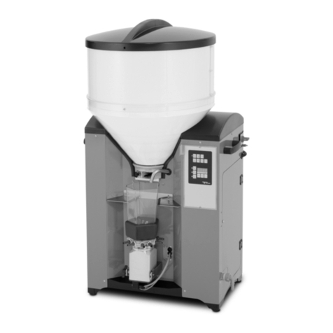
Cumberland PNEG-499 User manual

PNEG-499
Cycle Plus Pan Feeder
Installation and Operation Manual
PNEG-499
Date: 01-01-15

2PNEG-499 Cycle Plus Pan Feeder

Table of Contents
PNEG-499 Cycle Plus Pan Feeder 3
Contents
Chapter 1 Introduction ..........................................................................................................................................5
Introduction ............................................................................................................................................5
Chapter 2 Safety .....................................................................................................................................................6
Safety Guidelines ...................................................................................................................................6
Safety Instructions ..................................................................................................................................7
Safety Sign-Off Sheet ............................................................................................................................9
Chapter 3 Capacities and Specifications ..........................................................................................................10
Control Panel .......................................................................................................................................10
Tubing ..................................................................................................................................................10
Winching ..............................................................................................................................................10
Feeders ................................................................................................................................................10
Drive Unit .............................................................................................................................................10
Mechanical Tank Scale ........................................................................................................................10
Chapter 4 Planning Your System ......................................................................................................................11
Recommended Drive Unit Spacing ......................................................................................................11
Chapter 5 Installation ..........................................................................................................................................13
Grilless Feeder Assembly ....................................................................................................................13
Grilled Feeder Assembly (Continued) ..................................................................................................15
Feeder Tube Installation ......................................................................................................................18
Drive Unit Base Coupler Installation ....................................................................................................19
System Component Placement ............................................................................................................19
Grilled Centerhouse Control Unit Installation .......................................................................................20
Service Section Kit Installation .............................................................................................................21
Elbow and End Tube Assembly ...........................................................................................................22
Auger Installation .................................................................................................................................23
Auger Brazing ......................................................................................................................................26
Power Drive Unit Installation ................................................................................................................27
Feed Hopper Assembly ........................................................................................................................28
Shocker Wire Installation .....................................................................................................................30
Fill System Feed Level Control Switch .................................................................................................31
Winch Kit Installation ............................................................................................................................33
Cable and Winch Installation ................................................................................................................34
Drop Cable Installation .........................................................................................................................36
"Throwback" Installation .......................................................................................................................38
Cycle Plus Pan Feeder Control Installation ..........................................................................................38
Programming the Cycle Plus Pan Feeder Control ...............................................................................41
Chapter 6 Wiring Diagrams .................................................................................................................................43
External Wiring for Cycle Plus Pan Control (220 VAC 1 Phase) ..........................................................43
External Wiring For Cycle Plus Pan Control (220 VAC 3 Phase) ........................................................44
External Wiring for Cycle Plus Pan Control (380 VAC 3 Phase) ..........................................................45
Internal Wiring For Cycle Plus Pan Control ..........................................................................................46
Fill System Feed Level Control Switch Wiring .....................................................................................47

Table of Contents
4PNEG-499 Cycle Plus Pan Feeder
Chapter 7 Parts List .............................................................................................................................................49
Cycle Plus Pan Feeder System Components ......................................................................................50
Cycle Plus Pan Feeder Line Components ...........................................................................................51
Grilled Centerhouse Control Unit Components ....................................................................................53
Programmed Cockerel Feeder .............................................................................................................55
Grilless Feeder .....................................................................................................................................56
Cycle Plus Pan Feeder Power Drive Unit ............................................................................................57
Cycle Plus Pan Feeder Unloader .........................................................................................................58
120 Lb. Feed Hopper and Lid ..............................................................................................................59
Feed Level Control Switch ...................................................................................................................60
Flex-Flo Feed Level Control Switch .....................................................................................................61
Cycle Plus Pan Feeder Control Panel ..................................................................................................62
Chapter 8 Warranty ..............................................................................................................................................63

PNEG-499 Cycle Plus Pan Feeder 5
1. Introduction
Introduction
Cycle Plus Pan Feeder improves uniformity and feed conversion while reducing stressful in-house
migration and mortality. By running on a continuous cycle with a constantly ‘‘charged’’ line, the
Cumberland Cycle Plus Pan Feeder system eliminates ‘‘skips’’ in feed delivery, distributes feed evenly
and simultaneously to all pans on the line and assures equal access to feed for all birds...while generating
less feed separation than the typical programmed feeding system.

6PNEG-499 Cycle Plus Pan Feeder
2. Safety
Safety Guidelines
This manual contains information that is important for you, the owner/operator, to know and understand.
This information relates to protecting personal safety and preventing equipment problems. It is the
responsibility of the owner/operator to inform anyone operating or working in the area of this equipment
of these safety guidelines. To help you recognize this information, we use the symbols that are defined
below. Please read the manual and pay attention to these sections. Failure to read this manual and its
safety instructions is a misuse of the equipment and may lead to serious injury or death.
DANGER
WARNING
CAUTION
CAUTION
This is the safety alert symbol. It is used to alert you
to potential personal injury hazards. Obey all safety
messages that follow this symbol to avoid possible
injury or death.
This symbol indicates a potentially hazardous situation which,
if not avoided, may result in serious injury or death.
This symbol indicates a potentially hazardous situation which,
if not avoided, may result in minor or moderate injury.
This symbol indicates a potentially hazardous situation
which, if not avoided, may result in property damage.
This symbol indicates an imminently hazardous situation
which, if not avoided, will result in serious injury or death.

2. Safety
PNEG-499 Cycle Plus Pan Feeder 7
Safety Instructions
Our foremost concern is your safety and the safety of others associated with this equipment. We want to
keep you as a customer. This manual is to help you understand safe operating procedures and some
problems that may be encountered by the operator and other personnel.
As owner and/or operator, it is your responsibility to know what requirements, hazards, and precautions
exist, and to inform all personnel associated with the equipment or in the area. Safety precautions may be
required from the personnel. Avoid any alterations to the equipment. Such alterations may produce a very
dangerous situation where SERIOUS INJURY or DEATH may occur.
This equipment shall be installed in accordance with the current installation codes and applicable
regulations, which should be carefully followed in all cases. Authorities having jurisdiction should be
consulted before installations are made.
Follow Safety Instructions
Carefully read all safety messages in this manual and
safety signs on your machine. Keep signs in good
condition. Replace missing or damaged safety signs. Be
sure new equipment components and repair parts include
the current safety signs. Replacement safety signs are
available from the manufacturer.
Learn how to operate the machine and how to use controls
properly. Do not let anyone operate without instruction.
Keep your machinery in proper working condition.
Unauthorized modifications to the machine may impair
the function and/or safety and affect machine life.
If you do not understand any part of this manual or need
assistance, contact your dealer.
Read and Understand Manual
Practice Safe Maintenance
Understand service procedures before doing work. Keep area
clean and dry.
Never lubricate, service, or adjust machine while it is in operation.
Keep hands, feet, and clothing away from rotating parts.
Keep all parts in good condition and properly installed. Fix
damage immediately. Replace worn or broken parts. Remove any
built-up grease, oil, and debris. Maintain Equipment
and Work Area

2. Safety
8PNEG-499 Cycle Plus Pan Feeder
READ THESE INSTRUCTIONS BEFORE OPERATION AND SERVICE
SAVE FOR FUTURE REFERENCE
1. Read and understand the operating manual before trying to install or operate the Pan
Feeding System.
2. PowersupplyshouldbeOFFforserviceofelectricalcomponents.UseCAUTIONincheckingvoltage
or other procedures requiring power to be ON.
3. Never attempt to operate the Pan Feeding System by jumping or otherwise bypassing any safety
devices on the unit.
4. Keep the Pan Feeding System clean. Do not allow debris to collect around drive unit, control pan,
hoppers or boots.
5. Use CAUTION in working around the Pan Feeding System’s moving parts.
This product is intended for the use of feed handling only. Any other use is considered a misuse of
the product.
Some edges of the product’s components are sharp. Examine each product component to determine if
there are any safety considerations to be taken prior to use and/or installation. Any and all necessary
personal protective equipment should be worn at all times when handling, assembling, installing and
operation of the product and/or its components.
Throughout this manual, guards are removed for illustration purposes only. All guards must be in place
before and during operation.
For guidance or assistance on any issues relating to the safe use of Pan Feeder System,
Contact:
Cumberland
1004 E. Illinois St.
Assumption, IL. 62510
Phone: 1-217-226-4421
Operate Motor Properly
In an emergency, shut down the power source.
Turn OFF and lock out all power sources before performing
any maintenance.
Do not operate electric motor equipped units until motors are
properly grounded.
Disconnect power on electrical driven units before resetting
motor overloads.
Do not repetitively stop and start the drive in order to free a
plugged condition. Jogging the drive in this manner can damage
the equipment and/or drive components. Electric Shock Hazard

2. Safety
PNEG-499 Cycle Plus Pan Feeder 9
Safety Sign-Off Sheet
As a requirement of O.S.H.A., it is necessary for the employer to train the employee in the safe operating
and safety procedures for this auger. This sign-off sheet is provided for your convenience and personal
record keeping. All unqualified persons are to stay out of the work area at all times. It is strongly
recommended that another qualified person who knows the shut down procedure be in the area in the
event of an emergency.
Date Employee Name Supervisor Name

10 PNEG-499 Cycle Plus Pan Feeder
3. Capacities and Specifications
Control Panel
Feed distribution is entirely controlled from the fully programmable (for up to 48 hours) control panel. The
control panel is capable of a maximum of 10 feedings per day at any time of the day and may be ran for
any period of time. A fill system delay allows the fill line from the feed tank to turn ON before the feed
line, making sure the hoppers are filled before the feed line starts moving to prevent ‘‘skips’’ in the charged
line and unequal distribution to the pans. Control Panel Input: 50/60 Hz, 220 VAC, 1 Phase
Tubing
Four (4) hole, 9' (2.74 m) tubing
Four (4) hole, 10' (3.05 m) tubing
Four (4) hole, 12' (3.66 m) tubing
Maximum tube line length is 468' (143 m)
Winching
Drops should be placed at 8' (2.4 m ) or a maximum of 10' (3.05 m) intervals. Winching Equipment sold
and supplied by Cumberland is recommended.
Feeders
Grilled or Grilless feeders can be used, but the type of feeder to use depends on the preference or needs
of the producer.
Drive Unit
1/3 HP direct drive
64 RPM, 50 Hz or 60 Hz
Auger speed - 100 ft/min. (30-1/2" m/min.)
Mechanical Tank Scale
Capacity - 5000 lb. (2268 kg)
A model 350 Screener is needed on the weigh tank.

PNEG-499 Cycle Plus Pan Feeder 11
4. Planning Your System
Recommended Drive Unit Spacing
Careful planning, prior to beginning the installation, will save time and effort.
Houses up to 312' (95 m): Two (2) drive units are recommended. The drive units should be evenly
spaced opposite of each other at positions ‘‘A’’ and ‘‘C’’ as shown in Figure 4A.
Houses from 313' to 468' (95m to 142 m): Three(3) drive units are recommended. In order to determine
the proper drive unit spacing, add the total length of the system, including 8' (2.4 m) for each end, and
divide by 3. The result is the approximate number of feet between drive units, round up or down to the
nearest winching drop line. The drive units should be staggered and be placed at positions ‘‘A’’, ‘‘B’’, and
‘‘D’’ as shown in Figure 4B.
The following figures show houses with two Cycle Plus Pan Feeder loops. The first loop is to show
recommended drive unit spacing, and placement of the feed hopper, control pan, weigh tank, and service
section kit.
The second loop gives some dimensional specifications. Notice that the winching drop lines are spaced
8' (2.4 m) or 10' (3 m) apart through the system. Be sure to properly suspend the end sections of the loop.
NOTE: In pullet houses, the Cycle Plus Pan Feeder loop is 8' (2.4 m) wide.
Figure 4A Pullet House
Ref # Description Ref # Description
AWeigh Tank FFeed Hopper
B Fill Tank G Drive Unit
CAuger Travel HService Section
D Control Pan I Half House Brooding Curtain
EBrood End JWinching Drop Line

4. Planning Your System
12 PNEG-499 Cycle Plus Pan Feeder
NOTE: In breeder houses, the Cycle Plus Pan Feeder loop is 5' (1-1/2" m) wide.
Figure 4B Breeder House
Ref # Description Ref # Description
KWeigh Tank ODrive Unit
L Fill Tank P Service Section
MAuger Travel QWinching Drop Line
N Feed Hopper

PNEG-499 Cycle Plus Pan Feeder 13
5. Installation
Grilless Feeder Assembly
IMPORTANT: Do not use the grilless feeder without the locking clip. The clip is used to center the
feeder under the tube hole. If this clip is omitted, the feeder will slide off the hole and
cause feed spillage.
NOTE: Be sure the tabs are bent at 90° and are seated in the clip grooves completely.
Angle the grilless feeder insert into the top of the pan assembly. The insert reduces the feeder volume
when low feed rations are needed or every day feeding is required. (See Figure 5A.)
Figure 5A
Be careful when handling the tubes so as not to damage the tabs. Inspect each tube section. If the tabs
are damaged, use pliers to adjust accordingly. If it is necessary to rebend the tabs, be sure that no part of
the tab bend radius is within the diameter of the tube.
Install the locking clip on the tube. The tabs on the tube go through the hole in the locking clip.
(See Figure 5B.)
Figure 5B
Ref # Description
AGrilless Feeder Insert
B Pan Assembly
Ref # Description
CTube
D Locking Clip
End View

5. Installation
14 PNEG-499 Cycle Plus Pan Feeder
Grilless Feeder Assembly (Continued)
Install the drop tube cap over the locking clip. Install the cap from the side, with the hole in the tube
pointing down. (See Figure 5C.)
Figure 5C
Install the pan assembly from the opposite side, locking the ears over the drop tube cap. (See Figure 5D.)
Figure 5D
Rotate the feeder until the pan snaps into the locked down position. (See Figure 5E.)
Figure 5E
NOTE: The drop tube cap should have a "C" engraved on the top. If it does not,
contact your Cumberland representative.
Ref # Description
EDrop Tube Cap
Ref # Description
FEars
G Pan Assembly

5. Installation
PNEG-499 Cycle Plus Pan Feeder 15
Grilled Feeder Assembly (Continued)
Be careful when handling the tubes so as not to damage the tabs. Inspect each tube section. If the tabs
are damaged, use pliers to adjust accordingly. If it is necessary to rebend the tabs, be sure that no part of
the tab bend radius is within the diameter of the tube. (See Figure 5F.)
Figure 5F
Place the grill weldment over the drop tube.
IMPORTANT: The feeder assemblies must be placed onto the tubing before the tubing is
assembled together.
NOTE: When installing breeder houses, the male restriction bonnet must be placed onto the grill
weldment. This prevents males from eating out of the hen feeder system. Align the opening of the
bonnet with the opening of the grill and snap the bonnet over each grill wire.
Ref # Description
HGrill Weldment
I Drop Tube

5. Installation
16 PNEG-499 Cycle Plus Pan Feeder
Grilled Feeder Assembly (Continued)
Slide the feed level control onto the bottom of the drop tube, and place the pan onto the grill weldment by
squeezing the grill weldment together at the opening. The ring around the bottom of the grill weldment
should sit on top of the pan with the hooks supporting the pan under the ledge around the top of the pan.
(See Figure 5G.)
Figure 5G
Ref # Description
JFeed Level Control
K Male Restriction Bonnet
LPan

5. Installation
PNEG-499 Cycle Plus Pan Feeder 17
Grilled Feeder Assembly (Continued)
Slidethe proper number of feederassemblies onto eachtubesection. The feedtubetabs willslide through
the slot at the top of the drop tube.
Center the feeders over the holes and rotate the feeders on the tube with the tabs on the tube pointing
directly downward. The slots on the bell end of the tube should be aligned horizontally when the tabs are
pointing downward. (See Figure 5H.)
Figure 5H
Place the anti-rotation clips around the tubing and insert them into the slots in the top of the drop tube
(Two required). Being certain that the pan is level, lock the anti-rotation clips in place using the nuts and
bolts provided. (See Figure 5I.)
Figure 5I
Ref # Description
MAnti-Rotation Clip (Two Required)

5. Installation
18 PNEG-499 Cycle Plus Pan Feeder
Feeder Tube Installation
IMPORTANT: When installing a grilled feeder system, the pans must be installed on the tubing
prior to connecting the tubes together. Refer to on Page 13 -17 for grilled feeder
assembly instructions.
IMPORTANT: The unloader must be facing the same direction as the direction of auger flow. The orange
decals indicate the auger direction.
Installation should begin at the unloader in the center of the house. Check to see that structural
members are overhead to support winching the unloader and feed hopper. Lay out the tube sections in
the approximate location that they will be permanently installed. The belled end of the tubes will attach to
the unloader.
Using the 1-3/4" insulator package, fasten the tubes onto each side of the unloader. The tabs should be
pointing straight down, and the slots on the belled end will be horizontal. (See Figure 5J.)
Figure 5J
Working towards each end of the house, slide a 1-3/4" U-clamp onto the belled end of the tube before
inserting the straight end into it. Every fifth tube should receive a 1-3/4" insulator package for the shocker
wire. Make sure the tubes are inserted inside each other as far as possible and that the holes in the tubes
are in line and facing straight down before tightening. (See Figure 5K.)
Figure 5K
IMPORTANT: Do not over tighten the 1-3/4" U-clamps. Over tightening can deform the tubing.
Ref # Description
A1-3/4" (4.445 Cm) Insulator Package
B Unloader
CBelled End of Tube
Ref # Description
DBelled End of Tube
E 1-3/4" (4.445 Cm) U-Clamp
FStraight End of Tube

5. Installation
PNEG-499 Cycle Plus Pan Feeder 19
Drive Unit Base Coupler Installation
After connecting all the tubes together, mark the locations where the drive units will be installed. Refer to
thesection‘‘Planning’’ Your System"on Page 11,todeterminethe drive unitlocations.Cut out a 7"section
of tubing at the drive unit locations. Insert the cut tubes into the base coupler and tighten the four bolts on
each end to secure the tubes. (See Figure 5M.)
Figure 5L
System Component Placement
The grilled center house control pan is to be placed next to the feed hopper under the Flex-Flo drop kit.
The reason for this is to be able to shut off the Flex-Flo drop kit while half-house brooding. The service
section should be placed under the Flex-Flo control unit on the opposite side of the fill system than the
control pan. (See Figure 5M.)
NOTE: When installing the Cycle Plus Pan System for breeder house applications, the center house
control pan is not to be used.
Figure 5M
Ref # Description Ref # Description
ACut End of Tube CEnd Coupler
B Base Coupler
Ref # Description Ref # Description
AWeigh Tank FDrive Unit
B Flex-Flo Drop Kit G Feed Hopper
CAuger Travel HHalf-House Brooding Curtain
D Control Pan I Flex-Flo Control Unit
EBrood End JService Section

5. Installation
20 PNEG-499 Cycle Plus Pan Feeder
Grilled Centerhouse Control Unit Installation
The Cumberland grilled centerhouse control unit is used for partial house brooding.
IMPORTANT: Remove the unit from the box. Remove any shipping tape or packaging, i.e. on the paddle.
IMPORTANT: Do not over tighten the 1-3/4" U-Clamps. Over tightening can deform the tubing.
Cut out a 6" section of tubing at the proper location. Turn the unit so the paddle is facing the direction that
the feed is coming from. This will help to ensure that falling feed will not short-cycle the system.
Insert the cut ends of the tubes into the belled ends of tubing on the control unit. Make sure the tubes are
inside each other as far as possible and tighten the 1-3/4" U-Clamps. (See Figure 5N.)
Figure 5N
Adjustment
The grilled centerhouse control unit has switch adjustment screws which should be adjusted prior to bird
placement and then checked periodically.
A. Back the screws out counterclockwise until the switch actuates (clicks).
B. Turn the screw clockwise until the switch clicks again.
C. Turn the screws counterclockwise 1/2 to 3/4 of a turn more.
Some experimenting will need to be done to determine optimum performance. The objective is to achieve
maximum sensitivity without the vibrations from the feed line or falling feed causing quick or short-cycling.
Ref # Description
A1.750" (4.445 Cm) U-Clamp
B Grilled Center House Control Unit
CCut End of Tube
Table of contents
Other Cumberland Wire Feeder manuals
Popular Wire Feeder manuals by other brands

Vivid
Vivid Matrix Omni-Flow Product instruction manual

Dynapac
Dynapac MF2500CS operating instructions

FRONIUS
FRONIUS VR 1530-11 operating instructions

Migatronic
Migatronic MWF 8 instruction manual

RNA
RNA SLC 500-200 operating instructions

Oerlikon
Oerlikon DV 4004 CTLW Safety instruction for use and maintenance