Daihen OTC CM-0401-D User manual

OWNER'S MANUAL
WIRE FEEDER
MODEL: CM-0401-D
Ensure to read this
instruction manual
thoroughly for safe and
proper use of the product.
MANUAL No.: 632189-1 2023.11 EN

-2-
TABLE OF CONTENTS
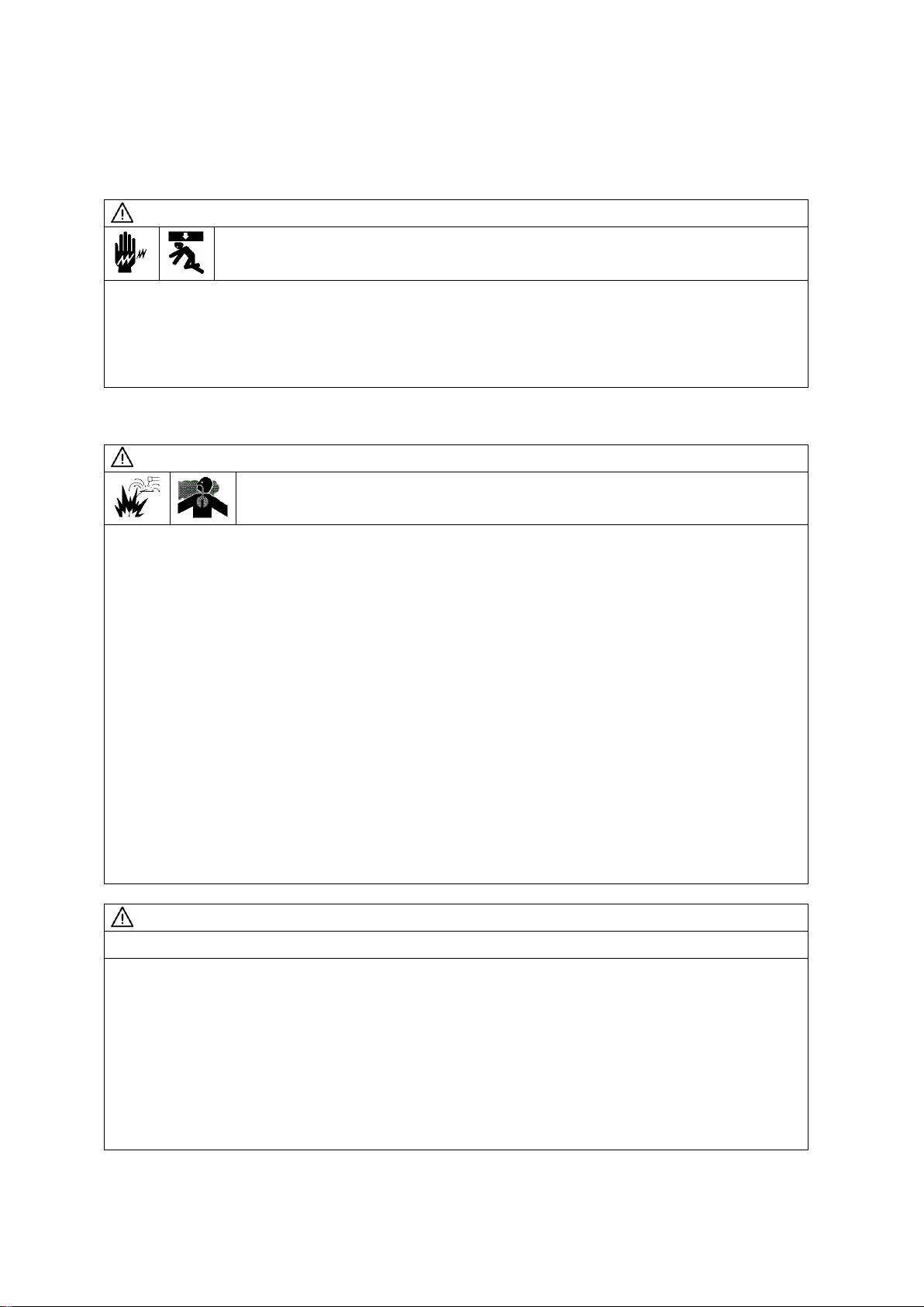
1SAFETY INFORMATION................................................................................................................. 3
2ARC WELDING SAFETY PRECAUTIONS .....................................................................................4
3CHECKING OF QUANTITY OF THE ACCESSORIES...................................................................9
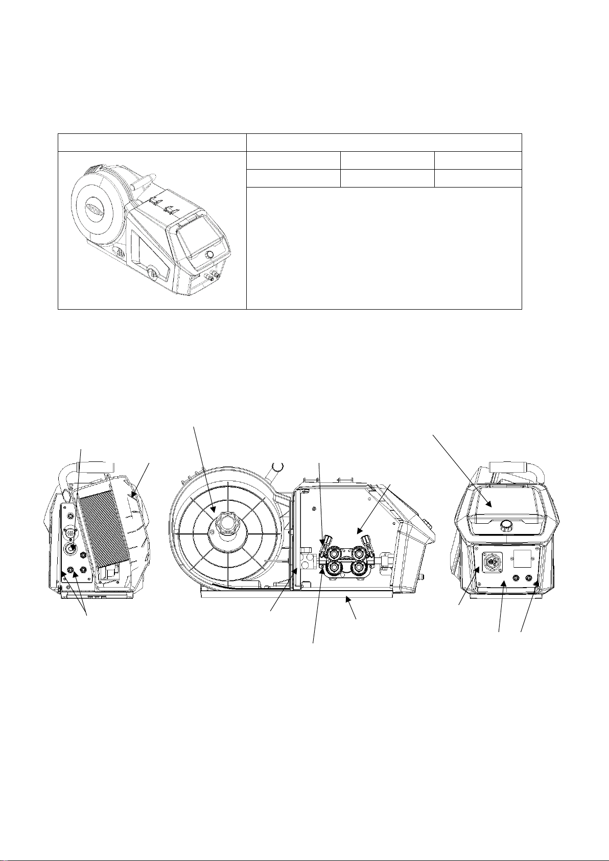
4NAMES OF PARTS.........................................................................................................................9
5CARRYING AND INSTALLING OF THE WIRE FEEDER.............................................................10
5.1 TRANSPORTATION......................................................................................................................10
5.2 INSTALLATION .............................................................................................................................10
6CONNECTION PROCEDURE.......................................................................................................11
6.1 CONNECTION FLOW CHART......................................................................................................12
6.2 CONNECTING OF THE WATER/GAS HOSE...............................................................................13
6.3 CONNECTING OF THE CONNECTION CABLE ..........................................................................14
6.4 CONNECTING OF THE POWER CABLE FOR WIRE FEEDER..................................................15
6.5 CONNECTING OF THE WELDING TORCH.................................................................................16
7WELDING PREPERATION ...........................................................................................................17
7.1 CHECKING OF WIRE SIZE / REPLACEMENT OF FEED ROLL .................................................17
7.2 FITTING OF WIRE.........................................................................................................................19
7.3 ADJUSTING OF THE WIRE PRESSURE.....................................................................................21
7.4 ADJUSTING OF THE WIRE REEL HUB.......................................................................................22
7.5 WIRE FEEDING BY PERFORMING INCHING OPERATION.......................................................23
8DIGITAL CONTROL PANEL .........................................................................................................24
8.1 SETTING INTERNAL FUNCTIONS ..............................................................................................24
8.2 TROUBLESHOOTING...................................................................................................................25
8.2.1 ACTION IN CASE OF ERROR.....................................................................................................25
8.2.2 ACTION IN CASE OF TROUBLE.................................................................................................25
9MAINTENANCE AND TROUBLESHOOTING...............................................................................26
9.1 CARRYING OUT MAINTENANCE................................................................................................26
9.2 REPLACING OF THE OUTLET GUIDE ........................................................................................28
9.3 REPLACING OF THE FEED MOTOR...........................................................................................30
9.4 REPLACE THE CENTER GUIDE..................................................................................................31
10 INTERMEDIATE CABLE ...............................................................................................................32
10.1INTERMEDIATE CABLE –WATER COOLED..............................................................................32
10.2INTERMEDIATE CABLE - GAS COOLED ....................................................................................32
11 PARTS LIST ..................................................................................................................................33
11.1MAIN BODY...................................................................................................................................33
11.2FRAME ASSY................................................................................................................................34
11.3MODULE........................................................................................................................................35
11.4DRIVE UNIT...................................................................................................................................36
11.4.1DRIVE UNIT - MECHANISM.......................................................................................................37
11.4.2 TORCH CONNECTION..............................................................................................................39
11.5FRONT PANEL ASSY...................................................................................................................40
11.6REAR PANEL ASSY......................................................................................................................41
11.7DIGITAL PANEL ............................................................................................................................42
11.8WIRE REEL DRUM .......................................................................................................................43
11.9OPTIONAL ACCESSORY.............................................................................................................44
11.9.1 WIRE STRAIHTENER................................................................................................................44
12. SPECIFICATIONS.........................................................................................................................45
12.1SPECIFICATIONS.........................................................................................................................45
12.2COMBINATION POWER SOURCES............................................................................................45
12.3EXTERNAL VIEW (mm) ................................................................................................................46

-3-
1 SAFETY INFORMATION
The following safety alert symbols and signal words are used throughout the manual to ensure proper
operation of the equipment and to prevent from various hazards that cause serious injury and damages.
Indication and explanation for the symbols are as follows:
Symbols
Explanation
WARNING
WARNING gives information regarding possible personal injury or loss of life.
CAUTION
CAUTION refers to minor personal injury or possible equipment damage.
PROHIBITED
PROHIBITED indicates “Prohibited” matters.

-4-
2 ARC WELDING SAFETY PRECAUTIONS
WARNING
ARC WELDING can be hazardous.
•PROTECT YOURSELF AND OTHERS FROM POSSIBLE SERIOUS INJURY OR DEATH.
Be sure to:
-Keep children away.
-Keep pacemaker wearers away until consulting a doctor.
•Read and understand the summarized safety information given below and the original principal
information that will be found in the PRINCIPAL SAFETY STANDARDS.
•Have only trained and experienced persons perform installation, operation, and maintenance of this
equipment.
•Use only well maintained equipment. Repair or replace damaged parts at once.
WARNING
ARC WELDING is safe when precautions are taken.
Before using this product, be sure to read this manual.
The device is manufactured using state-of-the-art technology and according to recognized safety
standards. If used incorrectly or misused, however, it can cause:
-injury or death to the operator or a third party,
-damage to the device and other material assets,
-belonging to the operating company,
-inefficient operation of the device.
All persons involved in commissioning, operating, maintaining and servicing the device must:
-be suitably qualified,
-have sufficient knowledge of welding,
-read and follow these operating instructions carefully.
The operating instructions must always be at hand wherever the device is being used. In addition to the
operating instructions, attention must also be paid to any generally applicable and local regulations
regarding accident prevention and environmental protection. All safety and danger notices on the
device:
-must kept in a legible stake,
-must not be damaged or marked,
-must not be removed,
-must not be covered, pasted or painted the covers.

-5-
WARNING
ELECTRIC SHOCK can kill.
Touching live electrical parts can cause fatal shocks or severe burns. The electrode and work
circuits
are electrically live whenever the output is on. The power line and internal circuits of
this equipment are
also live when the line disconnect switch is on. When arc welding all metal
components in the torch and
work circuits are electrically live.
•Do not touch live electrical parts.
•Wear dry insulating gloves and other body protection that are free of holes.
•Insulate yourself from work and ground using dry insulating mats or covers.
•Be sure to disconnect the line disconnect switch before installing, changing torch parts or maintaining
thisequipment.
•Properly install and ground this equipment according to its Owner’s Manual and national, state, and
local codes.
•Keep all panels and covers of this equipment securely in place.
•Do not use worn, damaged, undersized, or poorly spliced cables.
•Do not touch electrode and any metal object if POWER switch is ON.
•Do not wrap cables around your body.
•When the wire feeder is not in use or the work is interrupted for a long time, shut off the power of
all units.
•Blow dry air to parts periodically to remove dust and dirt.
WARNING
ARC RAYS can burn eyes and skin: FLYING SPARKS AND HOT METAL can
cause injury. NOISE can damage hearing.
Arc rays from the welding process produce intense heat and strong ultraviolet rays that can burn eyes
and skin. Noise from some arc welding can damage hearing.
•Wear face shield with a proper shade of filter (See ANSI Z 49.1 listed in PRINCIPAL SAFETY
STANDARDS) to protect your face and eyes when welding or watching a welder work.
•Wear approved safety goggles. Side shields recommended.
•Use protective screens or barriers to protect others from flash and glare: warn others not to look at
the arc.
•Wear protective clothing made from durable, flame-resistant material (wool and leather) and foot
protection.
•Use approved earplugs or earmuffs if noise level is high.
•Chipping and grinding can cause flying metal. As welds cool, they can throw off slag.
•Wear approved face shield or safety goggles. Side shields recommended.
•Wear proper body protection to protect skin.

-6-
WARNING
WELDING can cause fire and explosion.
Sparks and spatter fly off from the welding arc. The flying sparks and hot metal, spatter, hot base metal,
and hot equipment can cause fire and explosion. Accidental contact of electrode or welding wire to
metal object can cause sparks, overheating, or fire.
•Protect yourself and others from flying sparks and hot metals.
•Do not weld where flying sparks can strike flammable material.
•Remove all flammables within 10m (33ft) of the welding arc. If this is not possible, tightly, cover them
with approved covers.
•Be alert that welding sparks and hot metals from welding can easily pass through cracks and
openings into adjacent areas.
•Watch for fire, and keep a fire extinguisher nearby.
•Be aware that welding on a ceiling, floor, bulkhead, or partition can ignite a hidden fire.
•Do not weld on closed containers such as tanks or drums.
•Connect base metal side cable as close to the welding area as possible to prevent the welding
current from traveling along unknown paths and causing electric shock and fire hazards.
•Remove stick electrode from holder or cut off welding wire at contact tip when not in use.
•Does not use the welding power source for other than arc welding.
•Wear oil-free protective garments such as leather gloves, a heavy shirt, cuff less trousers, boots,
and a cap.
•A loose cable connection can cause sparks and excessive heating.
•Tighten all cable connections.
•When there is an electrical connection between a work piece and the frame of wire feeder or the
wire reel stand, are may be generated and cause damage by a fire if the wire contacts the frame or
the work piece.

-7-
WARNING
FUMES AND GASES can be hazardous to your health.
Arc welding produce fumes and gases. Breathing these fumes and gases can be hazardous to your
health.
•Keep your head out of the fumes. Do not breathe the fumes.
•Ventilate the area and/or use exhaust at the arc to remove welding fumes and gases.
•If ventilation is poor, use an approved air-supplied respirator.
•Read the Material Safety Data Sheets (MSDS) and the manufacturer’s instructions on metals,
consumables, coatings, and cleaners.
•Do not weld or cut in locations near degreasing, cleaning, or spraying operations. The heat and arc
rays can react with vapors to form highly toxic and irritating gases.
•Work in a confined space only if it is well ventilated, or while wearing an air-supplied respirator.
Shielding gases used for welding can displace air causing injury or death. Be sure the breathing air
is safe.
WARNING
CYLINDER can explode if damaged.
A shielding gas cylinder contains high-pressure gas. If damaged, a cylinder can explode.
Since gas
cylinders are normally part of the welding process, be sure to treat them carefully.
•Use only correct shielding gas cylinders, gas regulator, hoses, and fittings designed for the specific
application; maintain them in good condition.
•Protect compressed gas cylinders from excessive heat, mechanical shock, and arcs.
•Keep the cylinder upright and securely chained to a stationary support or a rack to prevent falling or
tipping.
•Keep cylinders away from any welding or other electrical circuit.
•Never touch cylinder with welding electrode.
•Read and follow instructions on compressed gas cylinders, associated equipment, and the CGA
publication P-1 listed in PRINCIPAL SAFETY STANDARDS.
•Turn face away from valve outlet when opening cylinder valve.
•Keep protective cap in place over valve except when gas cylinder is in use or connected for use.
•Do not disassemble or repair the gas regulator except for the person authorized by the manufacturer
of them.

-8-
WARNING
Be sure to observe the followings for preventing physical injuries, a fire and electric shock.
Handling of plastic parts. Front cover is made of polycarbonate.
Make sure to observe the following
notice.
•Do not apply external force and a shock to front cover. Otherwise it may be broken and in trouble.
•Polycarbonate can endure wiping off with water and alcohol in general but using at a sticking place
with an organic solvent, chemicals, cutting oil and atmosphere such as
composition oil, it gives bad
influence to polycarbonate and it causes a crack
(breaking) and a strength down.
•If abnormality was discovered such as crack on the front cover, stop operating
immediately and ask
to repair and change.
WARNING
Do not alter or remodel our products.
•You may get injured or have your equipment damaged because of fire, failure or malfunction
caused by altering or remodeling the product.
•The warranty does not cover any altered or remodeled products.
WARNING
Rotating parts may cause injuries. Be sure to observe the following.
If hands, fingers, hair or clothes are put near the fan’s rotating parts or wire feeder’s feed roll,
injuries
may occur.
•Do not use this equipment if the case and the cover are removed.
•When the case is removed for maintenance/inspection and repair, certified or experienced
operators must perform the work. Erect a fence, etc. around this equipment to keep others
away
from it.
•Before touching rotating parts for maintenance, inspection and repair, shut off the welding power.
•Do not put hands, fingers, hair or clothes near the rotating fans or wire feed roll.
WARNING
ARC WELDING work areas are potentially hazardous.
FALLING or MOVING machine can cause serious injury.
•When hanging the welding power source by a crane, do not use the carrying handle.
•Put the welding power source and wire feeder solidly on a flat surface.
•Do not pull the welding power source across a floor laid with cables and hoses.
•Do not put wire feeder on the welding power source, except on for that dedicated holder.
•Do not put the welding power source and wire feeder where they will pit or fall.
WELDING WIRE can cause puncture wounds.
•Do not press gun trigger until instructed to do so.
•Do not point gun toward any part of the body, other people, orany metal whenthreading weldingwire.

-9-
3 CHECKING OF QUANTITY OF THE ACCESSORIES
Check the quantity of parts when opening the package (DV code: 632876).
Wire feeder
Accessory
Description
Specification
Quantity
MANUAL
CM-0401-D
1
4 NAMES OF PARTS
Gas supply inlet
6.1
Water connection
(Water out / Water in)
Wire reel hub
Frame
Water connection
(Water out / Water in)
Pressure
handles
Pressure
roll holder
Wire straightener
Feed rolls
Torch socket
Digital control panel
Wire reel cover

-10-
5 CARRYING AND INSTALLING OF THE WIRE FEEDER
5.1 TRANSPORTATION
WARNING
Observe the following to avoid damage to the wire feeder or physical injury
when carrying the equipment.
•Do not touch the charging parts inside or outside the wire feeder.
•Disconnect the wire feeder from the welding power source by turning off the line disconnect switch in
the power box to avoid an electric shock before carrying the
equipment.
•Be sure to detach the wire reel from the wire feeder before lifting the equipment to the high places by
a crane.
5.2 INSTALLATION
WARNING
When installing the wire feeder, follow the instructions below to avoid
occurrence of fires during welding and physical damage by fume gas.
•Do not place the welding machine near combustible materials and flammable gas.
•Remove combustible materials to prevent dross coming into contact with combustible objects. If that
not possible, cover them with noncombustible covers.
•To avoid gas poisoning and danger of suffocation, wear a gas mask or adequately ventilate when
using the welding machine in the place regulated by a local law.
•Toprevent disorder or poisoning caused byfume, wear a gas maskor weld ata partial exhaust facility
approved by the local regulation.
•Adequately ventilate or wear a gas mask when using the welding machine in a tank, a boiler, a hold
of a ship, because heavier gas such as carbon dioxide or
argon gases are drifting there.
•When using the welding machine at a narrow space, comply with a trained supervisor’s directions.
And be sure to wear a gas mask.
•Do not operate the welding machine near the place where degreasing, cleansing, and spraying are
performed. Otherwise, poisonous gas may be generated.
•Be sure to wear a gas mask or adequately ventilate when welding a coating steel plate. (Poisonous
gas and fume may be generated.)
•Do not place the welding power source, wire feeder, torch, and control cable (including the extension
cable) in an area where the equipment can become wet.
CAUTION
Follow the instructions below when selecting an installation place for the wire feeder.
•Do not install in areas exposed to direct sunlight and rain.
•Do not place the welding power source, wire feeder, torch, and control cable (including the
extension
cable) in an area where the equipment can become wet.
•Install the wire feeder in the place where is altitude below 1,000m and the ambient temperature
is between -10 ˚C and +40 ˚C (+14 ˚F and +104 ˚F).
•Install a wind shield to protect arc from wind.
•Fix the gas cylinder to a stand specifically made for gas cylinders.
•Install it horizontal place as possible. (If install it in slant places inevitably, take measures to prevent
falling.)

-11-
6 CONNECTION PROCEDURE
WARNING
Follow the instructions below to avoid electric shock.
Do not touch live electrical parts, as this may cause in fatal shock and severe burns.
•Do not touch live electrical parts of the welding machine.
•Have a qualified electric engineer ground the case of the welding power source and the base metal
or jig electrically connected, following a local low.
•Disconnect the wire feeder from the welding power source by turning off the line disconnect switch
in the power box to avoid an electric shock before grounding the welding power source or base metal
and connecting the cables or hoses.
•Do not use a cable with lack of capacity or a damaged cable.
•Tighten and insulate the connections of cables.
•Firmly attach the cover of the welding machine after connection of the cables.
•Do not place the welding power source, wire feeder, torch, and control cable (including the extension
cable) in an area where the equipment can become wet.
•Insulate connected part of the bolt and the nut with the insulating tape surely after it tightens enough.

-12-
6.1 CONNECTION FLOW CHART
1
1
2
1
2
3
3
4
4
5
5
6
7
8
6
7
8

-13-
6.2 CONNECTING OF THE WATER/GAS HOSE
WARNING
You may suffer from danger of suffocation caused by lack of oxygen when shield gas
keep drifting in a closed place. Be sure to turn off the shield gas at the main when the
welding power source is not in use.
•Be sure to connect the gas hose after fixing to the stand, as physical injuries may result from the
gas cylinder toppling over.
•Attach a proper gas regulator to a gas cylinder. Failure to do so may result in physical injuries. The
gas regulator for high pressure gas must be used.
❖How to connect the water/gas hose
Connect the water/gas hose following the procedure shown below.
Attaching gas with coupler connection.
Attaching water with coupler connection.
Blue hose to blue connector.
Red hose to red connector.

-14-
6.3 CONNECTING OF THE CONNECTION CABLE
CAUTION
•Ensue that the torch connector is firmly attached. If the connector is not fully inserted, there may be
a risk of product damage.
❖How to connect the connection cables
Connect the connection cables following the procedure shown below.
Attaching control cable for wire feeder.
Attaching control cable for touch panel.

-15-
6.4 CONNECTING OF THE POWER CABLE FOR WIRE FEEDER
WARNING
Touching live electrical parts may cause in fatal electric shock and severe burns.
•Do not touch live electrical parts of the welding machine.
•Have a qualified electric engineer ground the case of the welding power source and the base metal
or jig electrically connected in accordance with a local low.
•Disconnect the wire feeder from the welding power source by turning off the line disconnect switch
in the power box to avoid an electric shock before the welding power source or base metal and
connecting the cables or hoses.
•After connecting the cables, cover the power source with the cover or case.
•When using the welding machine in such a humid environment as construction site, on the steel
plate, or on steel structure, install a leakage breaker.
•Use the proper power cable that matches the welding current.
CAUTION
•Use the proper power cable that matches the welding current.
Applicable current (Rated current)
Cable thickness
200 A
35mm2 or more
400 A*
50mm2 or more
500 A
75mm2 or more
* When performing pulse welding using the welding power source with 350 A applicable current
and a 17m or more cable, use the thicker cable by one rank.
❖How to connect the power cable
Connect the power cable following the procedure shown below.

-16-
6.5 CONNECTING OF THE WELDING TORCH
CAUTION
•Ensue that the torch connector is firmly attached. If the connector is not fully inserted, there may be
a risk of fire, burns, and product damage.
❖How to connect the welding torch
Connect the welding torch following the procedure shown below.

-17-
7 WELDING PREPERATION
7.1 CHECKING OF WIRE SIZE / REPLACEMENT OF FEED ROLL
Use feed rolls suited to the wire size. Using an improper feed roll will cause it slip to disable normal wire feed
or deform the wire, resulting in improper welding.
❖Procedure for checking feed roll
Check whether feed rolls suitable for the wire size are mounted following the procedure shown below.
❖Replacement of feed roll
Carry out the “Procedure for checking feed roll” in advance, and then dismount the feed roll with gear
following the procedure shown below.

-18-
Lock gear carrier.

-19-
7.2 FITTING OF WIRE
WARNING
•When the wire is set on the wire reel shaft, fully tighten the cap to prevent falling.
•In case a breakage, crack or deformation is found in the wire reel shaft or cap, do not use
but replace it.
❖Fitting of Wire
Fit the wire following the procedure shown below.

-20-
Table of contents
Other Daihen Wire Feeder manuals
Popular Wire Feeder manuals by other brands

Westfalia
Westfalia 7163-9001-044 Operating instructions and spare parts list

FRONIUS
FRONIUS WF 25i REEL R /SA/2R/G/W operating instructions

Abicor Binzel
Abicor Binzel MFS-V2 operating instructions

Miller
Miller R-115 owner's manual

ESAB
ESAB Origo Feed 304 Truck instruction manual

OHTAKE
OHTAKE OM-26R Series Operation manual