Curtech CT-I60012 User manual

Pure Sine Wave Power Inverter
DC-AC Inverter
Available models:
CT-I60012
CT-I100012
CT-I200012
CT-I300012
CT-I400012
CT-I100024
CT-I200024
CT-I300024
CT-I400024
CT-I400048


1
INTRODUCTION
Read this user manual completely before using the device. In the appendices
you will find the technical specifications of the pure sine wave power inverters.
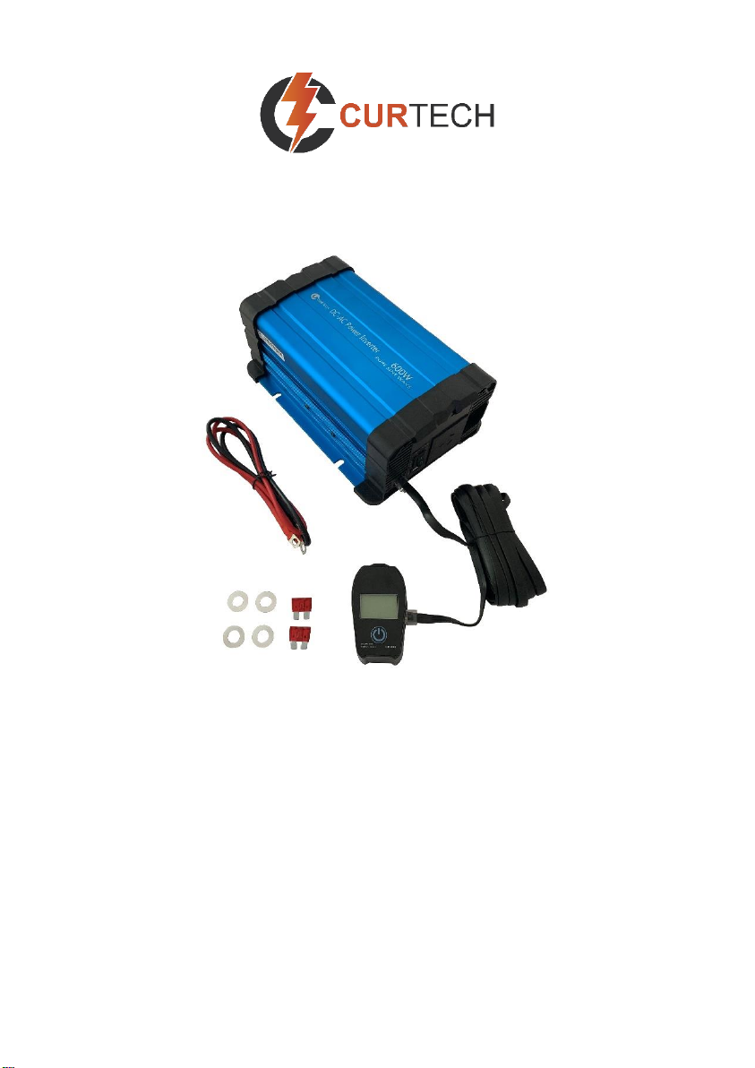
This DC-AC inverter converts a DC 12Volt, DC 24Volt or DC 48Volt voltage
(depending on the model purchased) into an AC voltage with a pure sine wave
(230VAC). With this device it is possible, with use of the right battery, to supply
equipment that normally requires a mains supply.
Important
Always check the actual power rating of the equipment (power consumption).
In addition, bear in mind the surge power. These (start-up) peaks can be as
much as 5-7 times the continuous power consumption. Check whether these
values are within the capacity limits of the inverter. Equipment with high surge
power are for example: air conditioner, vacuum cleaner, tools and pumps. If
you want to use multiple equipment at the same time, then add up the power
consumptions.
INSTALLATION
Mounting
The inverter must be mounted in a space that complies with the following:
•Mount the inverter in a dry place where there is no chance of it being
affected by moisture or dirt. Also, be aware of moisture or dirt that can be
sucked in by the fan.
•Leave enough space on all sides of the inverter (min. 10cm) for air
circulation and make sure that there is adequate ventilation.
•The ambient temperature must be between 0ºC and 40ºC. Ideal is
between 15ºC and 25ºC.
•Keep the inverter out of the reach of children.
•A working inverter produces a dangerous voltage.
•Do not use the inverter in places where gases are released, or flammable
materials are stored.
•The distance between inverter and battery should be as short as possible
but place the inverter in a separate room.
•Place the inverter on a stable surface and prevent (heavy) vibrations and
shocks.

2
Connection with the battery
Important
•Before connecting to the battery, make sure that the inverter is turned off.
•When the battery is connected a spark may be generated due to the
internal capacitor being loaded.
Preferably use the supplied battery cable set. For models which have two red
and two black cables included, always connect both cables on the + and -
side!
If you wish to use an own cable set, keep the cables as short as possible and
ensure the connections make good contact. The below formula indicates the
required cable thickness:
(Watts ÷ voltage) x length in meters x 0.2 = cable in mm2
Example: (600W ÷ 12V) x 2 meters x 0.2 = 20mm2
Working method:
1. Connect the cables to the inverter first:
The red cable to the red + input connection.
The black cable to the black –input connection.
Tighten the connections firmly.
2. Connect the other side of the cable to the battery:
The red cable to the + pole of the battery.
The black cable to the –pole of the battery.
Important
Make sure that you connect the correct cable to the correct pole, or damage to
will occur. Repair costs will not be covered by warranty.
Grounding
The AC output ground wire should be connected with the grounding point for
the connected equipment. Also wire the ‘ground’ connection on the inverter to
the chassis of the vehicle or ground stake.

3
Connection with the equipment
All inverters from the Curtech series have a socket for the connection of the
230VAC equipment. The models from 2000Watt have double sockets.
When connecting multiple appliances, it is important that the total load (Watts)
and surge powers fall within the capacity specifications of the inverter.
Important
•If the surge power is exceeded, the inverter will become damaged. Repair
costs will not be covered by warranty.
•Don’t mount the cables against the housing of the inverter.
The inverter in combination with other AC power supplies
In many situations it is desirable that the equipment will work on the mains
supply (or generator) when this is available. The inverter and mains supply (or
generator) then become one circuit.
Pay attention to the following:
Important
At the presence of a second power supply (mains, generator) this 230VAC will
be parallel on the output of the inverter. This will damage the inverter! Repair
costs will not be covered by warranty. If you want the equipment to work on
both an inverter and a second power source, then a power transfer switch
must be used. Important feature is that this power transfer switch is bipolar.

4
IN USE
•Check that the cables are mounted correctly. Never use the inverter when
the cables are damaged.
•Set the power switch to “ON” position.
•A warm housing is normal when the inverter is operating.
•If you will not be using the inverter for a significant period (during winter
storage for example), we recommend disconnecting it from the battery.
LED indications
•‘power’ (green) Battery connected and the on/off switch is in the ‘on’
position
•‘fault’(red) Fault occurred on the input side or internal temperature
•‘fault’(red, blinking) Fault occurred on the output side.
In case of a fault, consult the chapter ‘protections’ and the troubleshooting.
USB output
All models have an USB port. Here you can connect your 5Volt lead, like
mobile phone charger. The maximum load for this output is 2.1Amp.
Remote control
If the remote switch is connected, it is important that the main switch of the
inverter is in the ‘off’ position. After this, the inverter can be switched on and off
by using the remote switch.
The LCD display on the remote switch will display the battery voltage(V),
output power(W), battery capacity(Ah), lower voltage protection, over voltage
protection, over load protection, over temperature protection.
Fan
The fan is both temperature and load controlled. At a certain load level,
depending on the model, the fan will switch on automatically. Also, at an
internal high temperature the fan will switch on automatically.

5
What does the inverter consume from the battery?
A quick formula which gives a global indication of the current draw from the
battery is:
Watts ÷ voltage = current draw per hour
Example: a 3000Watt inverter in 12Volt consumes at full load:
3000W ÷ 12V = 250Amps per hour.
If the inverter has delivered this power for 10 minutes, then the current draw
from the battery is about 25Amp.
Remark: when a 3000Watt inverter delivers a power of 600Watt, then it
consumes also only 600Watt from the battery.
PROTECTIONS
Pre-warning (buzzer)
If the input voltage is becoming low, the inverter will emit an acoustic signal as
a warning.
Activation
De-activation
12Volt models
10.5Vdc +/-0.5
11.5Vdc+/- 0.2
24Volt models
21Vdc+/-0.5
23Vdc+/- 0.2
48Volt models
42Vdc+/-0.5
46Vdc+/-0.2
Low voltage protection
If, after the pre-warning, the input voltage still drops further, the low voltage
protection will eventually take effect. The AC output is shut down and the red
indicator ‘fault’ will light up. The buzzer will also continue to sound. If the input
voltage rises sufficiently, the inverter will automatically restart.
Shut down
Auto-restart
12Volt models
10Vdc+/- 0.5
12.6Vdc+/- 0.2
24Volt models
20Vdc+/- 0.5
25.2Vdc+/- 0.2
48Volt models
40Vdc+/-0.5
50.4Vdc+/-0.2

6
Over voltage protection
If the input voltage rises too high, the over voltage protection will come into
effect. The AC output is shut down and the red ‘fault’ LED lights up. If the input
voltage has dropped sufficiently, the inverter will automatically restart.
Shut down
Auto-restart
12Volt models
15.5Vdc+/-0.5
12.6Vdc+/- 0.2
24Volt models
31Vdc+/- 0.5
25.2Vdc+/- 0.2
48Volt models
62Vdc+/-0.5
50.4V+/-0.2
Important
The maximum input voltage that the inverter can tolerate is 16 Volts for a 12V
Inverter and 32Volts for a 24V Inverter. If the voltage that is supplied is higher
than this, then the inverter will be damaged. In this case the repair costs are
not covered by warranty.
Temperature protection
If the cooling provided by the fan is insufficient, the temperature protection will
be activated. The inverter will shut down the AC output and the red ‘fault’
indicator will light up. Once the inverter has cooled down sufficiently, it will
restart automatically.
Short-circuit on the output
The inverter will switch off the AC output voltage if there is a short-circuit of the
output. During this protection, the red ‘fault’ LED will flash slowly. The inverter
will restart automatically, once the problem has been resolved.
Overload protection
The inverter will shut down the AC output if the requested power on the output
is higher than the continuous power of the inverter. The red ‘fault’ indicator will
flash slowly. The inverter will restart automatically, once the problem has been
resolved.
Important
The overload protection only works with the maximum power and not with the
surge power. If the surge power of the inverter is exceeded, then the inverter
will be damaged. In this case the repair costs are not covered by warranty.

7
TROUBLESHOOTING
Problem
(Possible) Cause
Solution
A buzzer sounds
The input voltage is
becoming too low.
Charge the battery.
Red indicator
‘fault’ lights
Problem at the input side.
Battery voltage too low or
too high. The AC output is
shut down.
Check the input voltage.
Make sure that this value
falls between
specifications of the
inverter. The inverter will
restart automatically when
the input voltage is
between the limits again.
Temperature protection
active
Check that the fan is
working, and that the
inverter has sufficient
ventilation.
If the inverter is in a
location with a high
ambient temperature.
Place the inverter in a
cooler environment.
Reduce the load.
Red indicator
‘fault’ blinks
slowly
Problem on the output
There is a short-circuit or
overload. Check the
plugged-in appliance for
faults and the height of
the total load. When the
problem has been
resolved, the inverter will
restart automatically.

8
Problem
(Possible) Cause
Solution
‘Power’ LED
lights, but the
connected
equipment does
not work
Battery capacity too low to
supply the requested
power.
Connect a higher capacity
battery (set).
Weak connection between
battery and inverter.
Check all connections and
cables.
The cables used are too
thin.
Install cables matching
the length and capacity.
The requested power is
more than the inverter can
deliver.
Check the consumption of
the connected equipment.
Make sure that this falls
within the specifications of
the inverter.
Inverter does not
function at all. All
LEDs are off.
No input voltage present.
Check the connections
between battery and
inverter.
External fuses in battery
cable defective.
Replace the fuses (only
equivalent values).
Input voltage below the
minimal value.
Battery voltage too low or
battery defective.
Input voltage higher than
the maximum value.
Check if the system
voltage matches with the
inverter.
Check the DC power
supply voltage.
Internal defect
After completing the
above checks, if no fault is
found the inverter may be
damaged and require
repair.
Connected
equipment gives
disturbance.
‘Ground’ not connected
Connect the ‘ground’
connection of the inverter
to the chassis of the
vehicle.
Cabling is against the
housing of the inverter.
Make sure that the cables
do not touch the housing
of the inverter.

9
ACCESSORIES
Plug and play remote control with:
On/ off switch; working status LCD and error
display.
MAINTENANCE
ATTENTION: turn off the inverter before you start the maintenance activities!
To keep your inverter operating properly, there is very little maintenance
required. You should clean the exterior periodically with a slightly moist cloth to
prevent accumulation of dust and dirt. Also check periodically:
•all wires and connections. Replace damaged wires immediately.
•the ventilation vents
WARRANTY AND SERVICE
Before returning the inverter for repair, always read the Troubleshooting and
other information in this manual first. If a problem could have been solved by
means of this manual, we are obligated to charge the repair/diagnostic costs.
In case of a malfunction, the inverter can be sent to us directly or you can
choose to arrange the return with your dealer. Always include your contact
details and description of the problem. The inverter must be sent prepaid.
Curtech inverters carry a one-year warranty from invoice date. The warranty
period is only valid when the (copy) invoice is accompanied with the repair.
The warranty only covers the costs of parts and labour for the repair. The
warranty will lapse when a third party has attempted to repair the inverter or
when the inverter is not installed or used in accordance with the instructions.
Do not attempt to repair the inverter yourself.
The use of this inverter is the responsibility of the end user. The manufacturer
and importer cannot be held responsible for any damage resulting from use of
the inverter.

10
CT-I60012 Model
CT-I100012 & CT-I100024 Models

11
CT-I200012 & CT-I200024 Models
CT-I300012 & CT-I300024 Models

12
CT-I400012, CT-I400024 & CT-I400048 Models
Purchase Date:
/ /
Invoice Number:
Purchased From:
This manual suits for next models
9
Table of contents