HU
10
Precautions
Workspace
1. Welding equipment free of dust, corrosive gas, non-flammable materials, up to 90% humidity
for use!
2. Avoid welding outdoors unless protected from direct sunlight, rain, snow, work area tempera-
ture must be between -10 °C and +40°C.
3. Wall to position the device at least 30 inches away.
4. Well-ventilated area to perform welding.
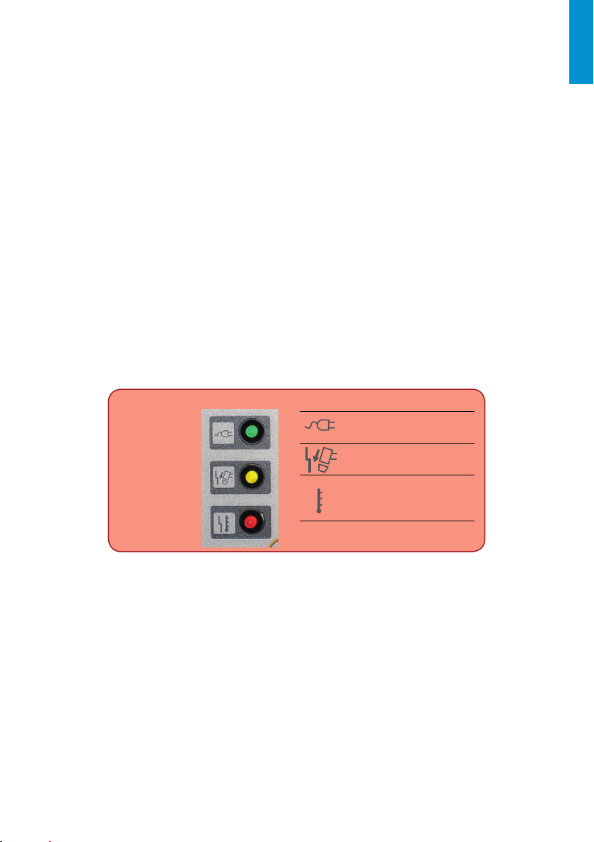
Safety requirements
Welding provides protection against overvoltage / overcurrent / overheating. If any of the
above events occurs, the machine stops automatically. However, over- stress damage to the
machine , keep the following guidelines :
1. Ventilation . When welding a strong current going through the machine , so the machine is
not enough natural ventilation for cooling . The need to ensure adequate cooling, so the
distance between the plane and any object around it at least 30 cm . Good ventilation is
important to normal function and service life of the machine.
2. Continuously , the welding current does not exceed the maximum allowable value. Current
overload may shorten its life or damage to the machine .
3. Surge banned ! Observance of tension range follow the main parameter table . Welding ma-
chine automatically compensates for voltage , allowing the voltage within permissible limits
of law. If input voltages exceed the specified value , damaged parts of the machine .
4. The machine must be grounded! If you are operating in a standard, grounded AC pipeline in
the event of grounding is provided automatically . If you have a generator or foreign , unfa-
miliar , non-grounded power supply using the machine , the machine is required for ground-
ing connection point earth to protect against electric shock .
5. Suddenly stopping may be during welding when an overload occurs or the machine over-
heats . In this case, do not restart the computer , do not try to work with it right away, but do
not turn off the power switch , so you can leave in accordance with the built-in fan to cool
the welding machines .
WARNING!
If the welding equipment is used with the welding parameters above 180 amperes, the standard
230V electrical socket and plug for 16 amp circuit breaker is not sufficient for the required cur-
rent consumption, it is necessary to use the welding equipment with 20A, 25A or even to the 32A
industrial fuses! In this case, both the plug and the plug socket fork have to be replaced to 32A
single phase fuse socket in compliance with all applicable rules. This work may only be carried
out by specialists!
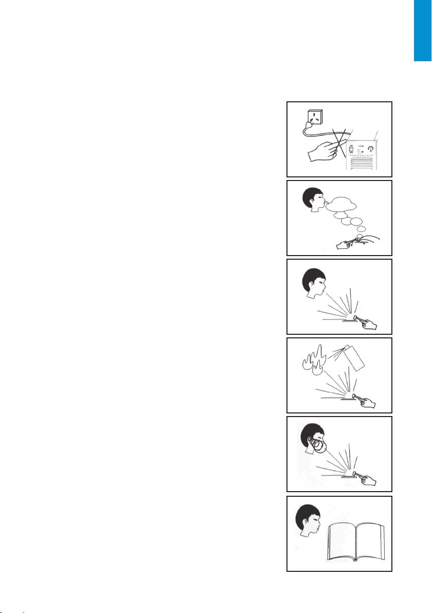
Maintenance
1. Remove power unit before maintenance or repair!
2. Ensure that proper grounding!
3. Make sure that the internal gas and electricity connections are perfect and tighten, adjust if
necessary, if there is oxidation, remove it with sandpaper and then reconnect the cable.
4. Hands, hair, loose clothing should be kept away under electric parts, such as wires, fan.
5. Regularly dust from the machine clean, dry compressed air, a lot of smoke and polluted air to
clean the machine every day!
6. The gas pressure is correct not to damage components of the machine.
7. If water would be, for example. rain, dry it in the machine and check the insulation properly!
Only if everything is all right, go after the welding!
8 When not in use for a long time, in the original packaging in a dry place.