DuroStar DS7000Q User manual

1
OWNER’S MANUAL
Air –Cooled Diesel Engine Generator Set
Max Tool Customer Service
Email support@maxtool.com or Call 1-800-629-3325 (option 3)
Monday –Friday 7am to 5pm PST
Product Support (Product: information, application, service info & warranty questions)
Email support@maxtool.com or Call 1-800-629-3325 (option 3)
Monday –Friday 7am to 5pm PST
This manual provides information regarding the operation and maintenance of these products.
We have made every effort to ensure the accuracy of the information in this manual.
We reserve the right to change this product at any time without prior notice.

2
- - - - Diesel Series Generator Set - - - -
Thank you for purchasing a DuroStar Diesel Series Generator.
This manual explains how to operate and service your diesel generator. Please
take the time to read it before operating your generator. Everyone who
operates this generator must read and understand this manual. The time you
take reading this manual before operating will ensure your safety and will
prolong your generator life. Pay special attention to statements preceded by
the following words:
DANGER
Indicates an imminently hazardous situation which if not avoided will result in
death or serious injury. This signal word is to be limited to the most extreme
situations.
WARNING
Indicates a potentially hazardous situation which, if not avoided could result in
a death or serious injury.
CAUTION:
Indicates a potentially hazardous situation which if not avoided could result in
minor or moderate injury. It may also be used to alert against unsafe practices.
NOTE: Provides helpful information.
With the unceasing improvement and enhancement of products, we reserve
the right to make improvement in design and/or changes in specifications at
any time without prior notice or obligation. User should pay attention that there
may be some differences between the contents described in the operation
instruction and practical products.
WARNING
This generator is designed to give safe and dependable service provided
it is operated per the instructions. Read and understand the operation
manual before operating generator. Failure to do so could result in
personal injury or equipment damage.
CAUTION:
Should no manufacturing standard be specially defined in the contract of order,
all generator set will be manufactured per GB/T2820.3-1997 or ISO
8528-3:1993 standard.

3
- - - - - - - - SAFETY TIPS - - - - - - - -
WARNING:
1. Preventing electrical shock:
The generator should be grounded to preventing electric shock. Never operate the
generator or handle any electrical equipment while standing in water, while barefoot,
while hands are wet, while in the rain or snow otherwise electric shock may result.
2. Preventing Fires:
Never add fuel to the fuel tank while the engine is running. Use a clean cloth to wipe
off the spilled fuel. Keep the diesel fuel, matches and other inflammable and explosive
matters away from the generator because the temperature around the muffler is very
high during operation. To prevent a fire hazard, it is necessary to provide sufficient
ventilation during the period of operation. At least 1m distance between the
generator, building and other equipment should be kept.
3. Preventing Burns:
Never touch hot muffler, hot exhaust manifold or engine cooling fans.
DANGER
4. This generator produces poisonous carbon monoxide gas that can kill you.
This gas is both odorless and colorless. Even if you do not see or smell gas,
carbon monoxide may still be present. Breathing this poison can lead to
headaches, dizziness, drowsiness, and eventually death.
•For outdoor use, ONLY, in non-confined areas. Never operate in an enclosed
area, indoors or near open windows or doors.
•Keep several feet of clearance on all sides to allow proper ventilation of the
generator.
5. Charging battery
Battery contains sulfuric acid which can cause blindness or severe burns. No
smoking, sparks or flames should exist when charging battery. In case of contact,
flush through with water and seek medical attention immediately, especially if your
eyes are affected
6. Other safety tips:
Know how to operate all the controls and how to stop the engine quickly. Keep
battery out of the reach of children. Operate on a level service. Keep vent caps tight
and level. The operator should wear safe shoes and working clothes.

4
Table of Contents
Important Pre-Operation Information and Safety Tips......................................2
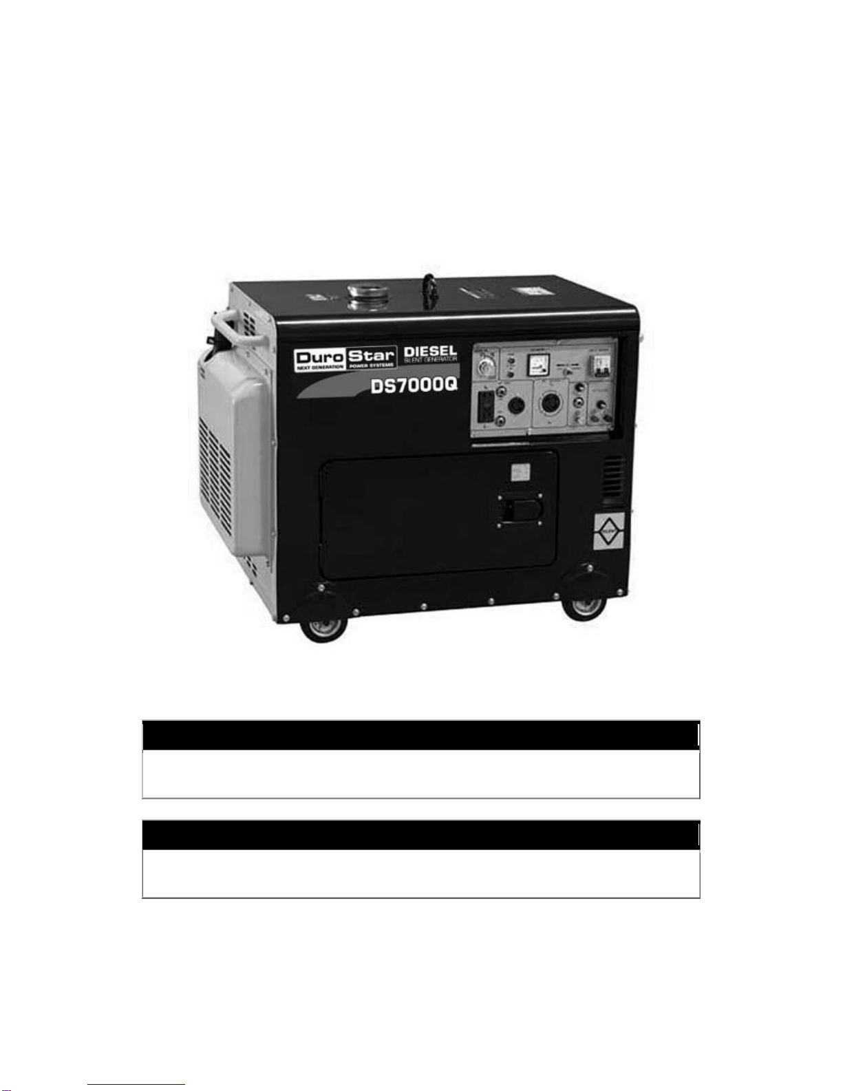
Series Appearance Diagram............................................................................5
1. Main Technical Specifications and Operation Circumstances..............6
1.1 Main Technical Specifications....................................................................6
1.2 Operation Circumstance ............................................................................7
2 Installation of Generator Set......................................................................8
3 Preparation for Starting..............................................................................9
3.1 Diesel Fuel, Air Cleaner Element, and Lube Oil.........................................9
3.2 Inspection for Diesel Generator Set.........................................................11
3.3 Bleed Air from the Fuel Line.....................................................................11
3.4 Before Starting, Operation must be done.................................................11
4 Start Generator Set...................................................................................11
4.1 Recoil Start ..............................................................................................11
4.2 Electric Start.............................................................................................14
4.3 Battery .....................................................................................................14
5 Operation for Generator Start..................................................................15
5.1 Operation of Diesel Engine......................................................................15
5.2 Generator Operating Speed.....................................................................15
5.3 Exercising the Generator Set...................................................................15
5.4 Open the Machine Case Door..................................................................16
6 Load Application.......................................................................................16
6.1 Determine Total Load Connected to the Generator Set...........................16
6.2 Start Electric Motors.................................................................................17
6.3 Extension Wire.........................................................................................18
6.5 AC Application .........................................................................................18
6.5 DC Application.........................................................................................18
6.6 Treat Machine with Double Voltage Output .............................................19
7 Stop the Generator Set.............................................................................19
8 Maintenance..............................................................................................20
8.1 Periodic Maintenance ..............................................................................20
8.2 Maintenance for Long Time Storage........................................................22
9 Inspection, Repair and Troubleshooting ................................................22
9.1 Doubtful Points and Problems..................................................................22
9.2 Inspection, Repair and Trouble Shooting.................................................22
Appendixes:
List for comments from users

5
MAIN TECHNICAL SPECIFICATION
1.1 Main technical specification
Type of set
Item
DS7000Q
Generator
Kind
Single phase
Frequency (HZ)
60
Max power (kw)
5.0
Max output (kiva)
4.5
Voltage (AC) V
120/240
Self-excitation
Brushless
Revolution (rpm)
3600
Voltage (DC) V
12
Current (DC) A
8.3
Optional generator
grade
G1
Power factor cos
1
Steady state voltage
adjust rate
+-7%
No-load waveform
distortion rate
·≤10%
Insulation grade
≤15%
Diesel engine
Mode of power
KD186FA
kind
4-stroke single–cylinder air cooled direct injection
Persistence power (KW)
6.6
Max power (kw)
7.3
Cylinder diameter*
stroke (mm)
86×72
Cylinder displacement
(ml)
418
Cooling system
Force air-cooled
Volume of lube oil (L)
1.65
Start system
Electric start
Fuel
Diesel fuel
Set
Fuel tank volume (L)
14.5
Working way
Continuous operating for 12hours
Total weight (kg/lb.)
172/379
Over dimensions (Inch)
37.8” x 22.0” x 30.3”
MAIN TECHNICAL SPECIFICATIONS AND OPERATION

6
CIRCUMSTANCE
Meaning of type symbols
※6500 Q --G1
G 1: Default type, used for
lights and other common
usage
Q: Low noise type
Code of power
Please confirm the model and functions of the generator set you purchased. For more
detailed information, contact the dealer.
1.2 Operation Circumstance
Under the following conditions, the generator set should output the rated power and
work reliably.
Altitude height
Ambient temperature (0)
Relative humidity
<1000(m)
-15~40 (0)
<90%
Please affirm your type of machine and understand its functions to operate and
maintain it correctly.

7
INSTALLATION
2 Installation of Generator Set
2.1 Outdoor Operation
Choose a location where the generator will not be exposed to rain, snow, or
direct sunlight. Position the generator on a secure and level ground so it will
not tip or slide down on a hill. Place the generator so that the exhaust fumes
will not be directed towards anyone.
The installation site must be free from water, moisture, or dust. All electrical
components should be protected from excessive moisture or the insulation
system will deteriorate and result in grounding or will short out the generating
system.
Foreign matter, such as dust, dirt, sand, lint, or abrasive materials can cause
damage to the generator and engine and are not allowed into its cooling
system.
2.2 Generator Set Grounding
The generator is equipped with grounding terminal
located on the rear of the opening type and at the low
position of back side of the silent type (refer to figure 2-1).
Ground the generator by tightening the grounding nut
against a grounding wire. A generally acceptable
grounding wire is a No. 12 AWG (American Wire Gauge)
stranded copper wire. This grounding wire should be
connected at the other end to a copper or
brass-grounding rod that is driven into the end.
Grounding codes can vary by location. Please contact a
local electrician to check the grounding regulations for your area.
WARNING:
Failure to properly ground the generator can result in electrocution.
WARNING
Always use electrical cords that are in good condition. Worn, bare, frayed or
other damaged cords can cause electric shock.
Before operation, the generator should be grounded to prevent electric shock.
Contact a licensed electrician to wire electrical plugs and/or cord sets.
Improper wiring could result in a fire or electrical shock.
DANGER
Never use your generator inside enclose areas or indoors. Engines consume
oxygen and give off deadly carbon monoxide poisonous gas. Improper
ventilation will cause damage to generator and injury to people.

8
PREPARE FOR STARTING
3 Prepare for Starting
3.1 Diesel Fuel,Air Filter Element, and Lube
Oil
Diesel Fuel
Use clean light diesel fuel only. If the fuel is
dirty, it should be filtered cleanly.
Caution: Don’t let any dust or water
mix with the fuel and enter the fuel tank.
Otherwise the high-pressure pump and
the injector nozzle get clogged.
Caution: Do not let fuel level rise
above Red Mark
Caution: No Smoking near oil or when
adding oil. Any sparks created can cause
fire or other damage. When filling oil,
don’t let oil overflow. After refueling,
make sure to fasten the cover nut on the
fuel inlet.
Type
Volume
DS7000
Series
The effective
volume of fuel
tank;(L) British
gal)
14.6
3.21
Type
Volume
DS7000Q
The effective
volume of fuel
tank;(L) British
gal)
12.8
2.82
Air Filter Element
Don’t wash the air filter element because the
component is a dry type. If the output of the
diesel engine drops or the color of the
exhausted gas changes adversely, change the
air filter element immediately. Never start the
diesel engine without using the filter element.
To check air filter element on silent model,
loosen the four screws from the outside body
fixed cover.

9
PREPARE FOR STARTING
Lube oil
Put the generator set at level state.
Fill lube oil into the inlet. Check the oil
level with dipstick by inserting the dipstick.
Don’t screw in the dipstick. Keep oil level
between high (H) and low (L) levels.
type
Volume
DS7000
Series
DS7000Q
Volume(L)
British(gal)
1.65
0.36
A. P.I Engine Service Classification
We recommend A.P.I CD grade
NOTE: Nothing affects the performance and durability of your diesel engine more
than the lube oil you use. If inferior oil is used, you may risk piston seizure, piston ring
sticking, accelerated wear of the cylinder liner and other moving components
significantly. Your engine life may be seriously shortened. We recommend CD grade oil
of API engine service classification. Always use oil with the right viscosity for the
ambient temperature. Use the above chart when choosing your engine oil.

10
PREPARE FOR STARTING
Caution: The machine has drained lube oil when it is delivered
from factory. Fill the crankcase with oil before starting.
3.2 Inspection for the Diesel Generator
3.2.1 When the oil pressure goes down below safe level,
the system will automatically shut off the engine to avoid
damaging while the ignition key is still in the ON position.
The engine will not start until the oil is refilled to proper
level. If the diesel engine is running with insufficient lube
oil, the oil temperature will raise. It is dangerous if there is
too much oil. This may cause lube oil to burn. It can then
cause the revolution speed of the diesel engine to
increase suddenly and result in abnormal running. For
this purpose, it is necessary to check the lube oil level
and the level should maintain between the low and high
level.
3.2.2 Turn off main switch and disconnect all load (For ex:
lamp and switch of motor). Check for damaged parts,
loose or missing nuts and bolts. If problems occur, please
do not start the engine, and consult our dealer.
Before starting the generator set, be sure to turn the main
switch to the OFF position. If the switch is not at the OFF
position, it can cause damage to the generator and seize
up the start motor with load to start.
WARNING: The generator should be started
without load.
3.3 Bleed Air from the Fuel Line
If the engine is having difficulty starting and the
fuel and oil level are acceptable, the problem can
usually be traced to air bubbles trapped in the
fuel line. The air should be discharged.
The correct method is:
Turn the fuel cock beneath the fuel tank to the
OFF position. Disconnect the fuel distributing
pipe from high pressure pump. Turn the valve to
the ON position and allow fuel to drip from the
fuel line to a small container. Reattach the fuel
line to the fuel pump when no air bubbles appear.
3.4 Before starting the generator, make sure
you have done the following:
a. The generator is positioned on a firm level
surface.
b. The generator has been grounded.
c. Check the lube oil level.
d. Any spilled fuel has been wiped off.
e. The ventilation is good.
4 Start Generator Set
4.1 Recoil Start
For the detailed start steps, please refer to
the operation diagram on the next page.
NOTE: On a cold day when it is difficult to
start the diesel engine, screw out the screw
plug on the cover of the diesel engine and fill
in 2 ml of lube oil.
CAUTION: When filling oil, the plug
screw should be screwed tightly on the
cover to prevent dust and moisture
sucked into the cylinder and can cause
accelerated wear of internal parts.

11

12

13
START GENERATOR
4.2 Electric Start
(1) Disconnect all loads to generator.
(2) Turn the main switch to “OFF” position.
(3) Turn the fuel cock to “ON” position.
(4) Turn the ignition key to “ON” position. Wait a
few moments and then turn the key to “START”
position.
(5) After the diesel engine starts, remove your
hand from the ignition key. Let the switch restore
to “ON” position.
CAUTION: When the diesel engine is
running, never draw out the start handle;
otherwise it will damage the diesel engine.
DANGER: Charging a battery produces
colorless explosive gases which can cause
blindness or injury. No smoking, sparks, or
flames should exist when charging battery.
Never charge a visibly damaged or frozen
battery.
Note: Some models my come with a
sealed type battery, the above electrolyte
service is not required.
4.3 Battery Application
If your generator is used for the first time, you
should fill electrolyte in the battery. For detailed
steps, please refer to your battery instructions.
Check the level of electrolyte of the battery once
a month. Charging the battery consumes
electrolyte. When the liquid level goes down to
the lower mark, add distilled water to top mark.
If the electrolyte in the battery is low, the diesel
engine may not start because the electric power
is insufficient.
If the electrolyte in the batter is overfilled, the
liquid may spill and it may corrode its
surrounding components.
Charge the battery once a month. For electric
start type generators, it can charge the battery
automatically during the period of operation If
your generator is used for spare power supply,
pay attention to charge time.
NOTE: Keep battery out of reach of children.
Do not allow battery to be un level or tip
over. Keep vent caps tight and level.
CAUTION: Keep the liquid level of battery
between the upper limit and the lower limit.
Battery electrolyte contains sulfuric acid
which can cause blindness or burns.

14
OPERATE YOUR GENERATOR
5 Operation for Generator Set
5.1 Handle the Diesel Engine
5.1.1 Avoid overload
While your diesel engine is new, applications
of heavy loading may shorten the engine’s life.
It must run a light load within the first 20 hrs.
(1) Avoid overload: Avoid applying any heavy
load during the initial 20 hrs.
(2) Change the lube oil regularly: Change the
lube oil after 20 hours of initial operation or at
the end of the first month and then once every
50 hours for 3 times, every 3 months, or every
1000 hours thereafter.
NOTE: The lube oil should be drained while
the diesel engine is hot. If cooled, it is very
difficult to drain the engine oil completely.
5.1.2 Warm up the diesel engine for 5 minutes
without any load.
5.1.3 Check the indicator lamp
Though equipped with low oil pressure
protection system, it is necessary to check
whether the indicator lamp of oil pressure
signal lights up. The lube oil alarm indicator
will light when the oil pressure is low or the
lube oil is insufficient and the diesel engine will
shut off automatically. The engine will not be
started until refilling oil to safe level.
5.2 Inspection during the engine running.
(1) Abnormal sound or vibration;
(2) Color of exhausted gas, black or white;
(3) Excessive change in engine speed;
(4) Sparking or arcs from generator;
(5) Loss of electrical output;
(6) Engine has Fire.
(7) Flame or Smoke.
If you find one of the above-mentioned issues,
it is necessary to turn off machine. Please
contact the dealer.
5.3 Generator Operation Speed
The generator must be run at the correct
speed to produce the proper electrical voltage
and frequency. The speed of the engine was
carefully adjusted at the factory so the
generator produces the proper voltage and
frequency.
WARNING: Do not adjust the speed or fuel
limit bolt of the diesel engine. (They were
properly adjusted when delivered from
factory) If changed, the engine’s
performance will be affected.
Before connecting a load to the generator, the
pointer of the voltmeter should be in the green
area to ensure the generator is working
properly. Failure to do so could result in
damage to the equipment plugged into the unit
and possible injury.
All engines tend to slow down when a load is
applied. When the electrical load is connected
to the generator, the engine is more heavily
loaded and thus the speed drops slightly. This
slight decrease in speed together with the
voltage drop results in a slightly lower voltage
when the generator is loaded to its full
capacity than when it is running with no load.

15
OPERATE YOUR GENERATOR SET
The slight variation has no appreciable effect in
the operation of motors, lights, and most
appliances. Electronic equipment may be
affected if correct speed is not maintained.
Output voltage should be checked periodically
to ensure continued proper operation of the
generating plant and appliances. It can be
checked by using an electric clock with a sweep
second hand timed against a watch or stop
watch. The clock should be correct within + -2
seconds per minute. Aqualified technician
should do all speed setting adjustments.
5.4 Exercising the Generator
The generator should be operated every four
weeks. Warm the unit up by starting the engine
and letting it run for 10-15 minutes. This will dry
out any moisture that has accumulated in the
windings. This moisture can cause corrosion in
the winding. Frequent operation of the engine
generator will also ensure that set is operating
properly should it be needed in an emergency.
5.5 How to open the machine case door (Q
series set)
Rotate the know switch counter clock wise to
open the door the of mechanical case and carry
out the daily check.
6.Load application
6.1 Determine total electrical load
It is important to determine the total electrical
load before connecting to the generator. The
two major factors in determining the life of a
generator head are: Heat buildup caused by
over loading the generator and corrosive
contaminants that attack the wiring insulation. If
the generator is overloaded, the wires become
excessively hot and cause the insulation to
break down, reducing its ability to resist
corrosive contaminants. Over time the
effectiveness of the insulation is eliminated and
a dead short can result.
Always compare the generator nameplate data
with that of the equipment to be used to ensure
that watts, volts, amperage, and frequency
requirements are suitable for operating
equipment. May require three to ten times more
wattage if influenced by the equipment
efficiency and power factor.
NOTE: If wattage is not given on equipment
nameplate, approximate wattage may be
determined by multiplying nameplate voltage by
nameplate amperage
Example: VOLTS × AMPS= WATTS
120V × 5A= 600W
When connecting a resistive load as in
candescent lights, heaters or common electric
power tools, a capacity of up to the generator
full rated wattage output can be used.
When connecting a resistive-inductive load
such as a fluorescent or mercury light,
transformer or inductive coils, a capacity of up
to 0.6 times of the generator full rated output
can be used.

16
LOAD APPLICATION
Use this chart to estimate the total load on your generator
For determining generator load requirements
Device
Air
Conditioner(12,000BTU)
Battery Charger (20Amp)
Belt Sander
Chain Saw
Circular Saw (6-12)
Coffee Maker
Compressor (3/4HP)
Compressor(1/2HP)
Curling Iron
Dishwasher
Edge Trimmer
Electric Nail Gun
Electric Range (1
Element)
Electric Skillet
Furnace Fan (1/3)
Freezer
Hair Dryer
Hand Drill
Hand Drill
Hand Drill
Hand Drill
Hedge Trimmer
Home Computer
Impact Wrench
Jet Pump
Lawn Mower
Light Bulb
Microwave Oven
Milk Cooler
Oil Burner on Furnace
Oil Fired Space
Htr(14,000Btu)
Oil Fired Space
Htr(85,000Btu)
Oil Fired Space
Htr(30,000Btu)
Oven
Paint Sprayer(1/3HP)
Paint Sprayer Airless
Radio
Refrigerator
Slow Cooker
Submersible
Pump(1-1/2HP)
Submersible Pump(1HP)
Submersible
Pump(1/2HP)
Sump Pump
Table Saw(10i)
Television
Toaster
Vacuum Cleaner
VCR
Water Heater
Running Watts
1700(a)
500
1000
1200
900
1000
2000a
1800a
1400a
700
500
1200
1500
1250
1200a
800b
1200
1100
875
500
250
450
150
500
800a
1200
100
700
1100a
300
400
225
150
4500
600(a)
150
200
600(b)
200
2800(a)
2000(a)
1500(a)
600(a)
2000(a)
500
1000
250
70
3000
(a) Hard-starting motors require 3 to 5 times
the rated running watts.
(b) These loads may require up to 15 minutes
to restart due to its normal build up of
compressor.
CAUTION: Always allow the generator
to reach operating speed before a load is
applied.
6.2 Starting electric motors
Electric motors require much more current
(amps) to start than to run. Some motors,
particularly low cost split-phase motors, are
very hard to start and require 5 to 7 times
more current to start than to run, Capacitor
motors are easier to start and usually require
2 to 4 times as much current to start than to
run. Repulsion induction motors are the
easiest to start and require 1.5 to 2.5 times as
much to start than to run.
Most fractional motors take about the same
amount of current to run them whether they
are of repulsion-induction (RI). Capacitor
(CAP) or split –phase (SP) type. The following
chart shows the approximate current required
to start and run Cap type and size of 220 volt
50cycle electric motors under various
conditions.
220v,50HZ Motors
Starting Amps
Hp motor
Running amps
Cap type
10.5
0.75
1.1
1.5
2.2
3
2.3
3.5
5
7
10
15
12-16
17-24
25-35
34-49
50-70
68-95
The figures given above are for an average
load such as a blower of fan. If the electric
motor is connected to a hard-starting load
such as an air compressor, it will require more
starting current. If it is connected to a light
load or no load such as a power saw. It will
require less starting current. The exact
requirement will also vary with the brand or
design of the motor.
CAUTION: To start the motor above
1.5kw power. The G2, G3 grade
generator should be selected and
method of drop voltage starting must be
carried out. For detailed step, consult
with our dealer or with us directly.

17
LOAD APPLICATION
To hard start load such as an air compressor or
air conditioner, consult the dealer to determine
the max power.
Generator responds to severe overloading
differently than the power line. When
overloading, the engine is not able to supply
enough power to bring the electric motor to
operating speed. The generator responds to the
high initial starting current but the engine speed
drops dramatically. Overloading may stall the
engine. If operated at very low speeds, the
electric motor winding will burn out quickly. The
generator head winding may get damaged.
Running the generator under these conditions
may result in damage to the generator stator as
well as the rotor windings because the heavy
surge of current is required for only an instant.
The generator will not be damaged if it can
bring the motor up to speed in a few seconds.
Turn off all other electrical loads. If possible,
reduce the load on the electric motor.
6.3 Extension cords
When electric power is provided to various
loads at some distance, extension cords can be
used. These cords should be sized to allow for
distance in length and amperage so that the
voltage drop between the set and point of use is
held to a minimum.
Current/power
Cord cuts
Amps
at
240V
Load)
watts
Cord
Length
80m
Cord
length
50m
Cord
length
30m
Cord
Length
20m
10
15
20
25
30
2400
3600
4800
6000
7200
8
10
10
12
12
4
8
8
10
10
4
6
6
8
10
2.5
4
6
6
8
CAUTION: Equipment damage can result
from the voltage caused by using an
extension cord with a small wire size.
6.4 AC Application
(1) Observe the indicating voltmeter on the
control panel. The pointer should be in the
green area for load conditions.
(2) When connecting load to the generator,
equipment should be connected in order.
First connect heavy to light load to
generator, then connect restive inductive
load, then re-restive load. If operation order
is improper, the engine speed may drop
sharply and the load should then be
disconnected immediately and checked for
causes.
(3) Balance of three phase generators for
load: When connecting single phase load,
each phase cannot exceed 1/3 of generator
rated power and difference between each
phase amps’ value should not exceed 20%
rated current.
CAUTION: Serious misbalanced load
connected to each phase can cause
burn out of generator set.
If the circuit overload makes the overload
protection switch (main switch) of AC circuit
trip, it is necessary to reduce the circuit
load. Wait several minutes before restoring
the operation. If the indication on the
voltmeter is too high or too low. It is
necessary to stop the generator.
6.5 DC application
Both DC terminals provided output: DC12V,
8.3A, the red terminal is I =i(positive)pole of
power supply. It can be used as load for
rated voltage DC12V and used for charging
12V battery.
(1) To charge the battery with two leads
connected to the start circuit, the negative
lead should be disconnected from the
generator.
(2) Connect the positive and negative
poles of the battery with the positive and
negative poles of DC terminal.
CAUTION: Be careful not to connect
positive and negative leads adversely,
otherwise the generator and the
storage battery will be damaged
severely. Do not let positive and
negative leads touch each other, or the
storage battery will short circuit.

18
LOAD APPLICATION / STOPPING THE GENERATOR /
GENERATOR MAINTENANCE
NOTE: The DC output current should not
be more than 8.3A, when charging the
large capacity battery. The fuse from the
DC power supply may burn off and can
break easily for large charging current.
DANGER: Charging battery produce
colorless explosive gases which can
cause blindness or injury. Do not let any
spark, flame or smoking near generator.
To avoid producing sparks near the
battery, first connect the lead with the
battery, then connect the lead with the
generator. When disconnecting, battery
disconnect the ground motor cable first.
Charging the battery should be in a place
with good ventilation. Before charging,
open vent caps of battery. If the
temperature of electrolyte is over 45 C,
terminate charging.
6.6 Treat machine with duplex voltages
output.
Before the generator applies AC, power
supply make sure it is the correct rated
voltage of load. Then choose the output
voltage through the transformer switch on the
output panel. Voltage can be measured
through the voltmeter or indicating lamp of
power supply at output panel.
CAUTION: Before using the voltage
transformer switch, be sure to disconnect
all loads from the generator.
7 Stop the Generator Set
Disconnect all loads from the generator set.
Set the speed lever of the engine to the
“RUN” position. Operate the diesel engine for
about three minutes without load. Do not stop
the diesel engine dramatically. Doing so can
cause the engine temperature to rise and
result in a blocked injector nozzle damaging
the engine.
Follow steps below to stop engine:
(1) Disconnect all loads from generator set.
(2) After 3 minutes of running without load,
turn the ignition key to “OFF” position.
(3) Set the fuel cock lever to “S Position”
(4) Turn the fuel cock too “OFF” position.
CAUTION: When speed lever is set to
“STOP” position and the diesel engine is
still in operation. It is possible to stop the
diesel engine by setting the fuel switch
“OFF” position or by unfastening the
high-pressure fuel pump nut. Do not break
the diesel engine with the decompression
lever.

19
MAINTENANCE
8 Maintenance
8.1 Regular maintenance
To keep the generator in a good state, the periodic inspections and maintenances are very
important. The generator set consists of a diesel engine, generator, control panel, frame and
so on. For details about the inspection or maintenance, please refer to the relative operation
and maintenance instructions.
CAUTION: Before maintenance, please turn off the diesel engine. Disconnect the
battery from the generator. First disconnect the negative cable then the positive.
After using the generator, it is necessary to wipe off the dirt on it with clean cloth to prevent
corrosion and remove the precipitate.
Generator maintenance: The single-phase generator is brushless and maintenance free for
three phase generators, consult with the dealer. Any major generator services including the
installation or replacement of parts should be performed only by a qualified electrical service
technician. Use only factory approved parts.
Service period regular
Item
Daily
The first month or
after 20 hours
The third
month or
after 100
hours
The sixth month or after
500 hours
Every
year or
after
1000
hours
Check and replenish fuel
○
Drain fuel
○
Check and replenish lube oil
○
Check for fuel leakage
○
Check and fasten every
fastening parts
○
●
Fasten head bolts
Change lube oil
(the 1st time) (the
next three times
change interval
are 50 hours)
○ (the 5th
time)
Clean the filter of lube oil
○ (change it if necessary)
Chang air filter
(service more frequently
when used at dusty areas)
(change)
Clean fuel filter
○
change
Check fuel injection pump
●
Check fuel injection nozzle
●
Check fuel pipe
(change it if necessary)
Adjust valve clearance for intake
and exhaust valves
●
Mill intake and exhaust valves
●
Replace piston ring
●
Check electrolyte of battery
Every month
Note: ● symbol means you need a special wrench, please contact dealer.

20
MAINTENANCE
8.1.1 Change lube oil
Screw out the dipstick and remove the drain
plug. Drain old lube oil while the lube is still
hot. The drain plug is located at the bottom of
the cylinder block. Fasten the drain plug then
fill with the recommended lube oil.
Change the lube oil after 20hrs of initial
operation or at the end of the first month, and
then once every 50hrs for three times, once
every three months, or once every 100 hours
thereafter.
8.1.2 Clean the lube oil filter
Loosen the fasten bolt and pull out oil filter to
clean
Time to be cleaned
Every 6 months or
every 500 hours
Replace it if necessary
8.1.3 Change the air filter
Don’t clean the air filter or air element with
detergent, use a soft brush clean dust
accumulated on the external surface of
element.
Time to be cleaned
Every 3 months or
every 100hours
CAUTION: Never start the diesel
engine without the filter element. Change
any damaged or old filter element when
needed.
8.1.4 Clean and replace the fuel filter
The fuel filter should be cleaned regularly to
insure maximum output power.
Time to be cleaned
Every 6 months or
every 500 hours
Time to be replaced
Every year or every
1000 hours
(1) Drain the fuel oil from the fuel tank
(2) Loosen the small screw of the fuel cock
and pull out the filter from fuel filling mouth.
Wash it thoroughly with diesel oil.
(3) Fuel filter on silent type generator is
locate beneath the fuel tank, open the case
door so you can see it and disassemble.
Clean or replace as necessary.
Time to be cleaned
Every 3 months or
every 1000 hours
8.1.5 Fasten cylinder head bolts (refer to
operation instructions of diesel engine)
8.1.6 Check the injection nozzle and
injection pump.
8.1.7 Adjust the valve clearance for the
intake and exhaust valves.
8.1.8 Replace piston ring.
The operations from 8.1.5 to 8.1.8 require
specific tools and skills. Do not try it yourself.
CAUTION: When operating, do not
expose bare skin to fuel spray. The fuel
can penetrate the skin and cause injury.
Other manuals for DS7000Q
1
Table of contents
Other DuroStar Inverter manuals
Popular Inverter manuals by other brands

Omron
Omron KP**G-OD Series Communications manual

Fuji Electric
Fuji Electric FRENIC-AQUA series user manual

SolaX Power
SolaX Power X1-ESS G4 user manual

EELP
EELP PSL Series Assembly, installation and operation instructions

ABB
ABB PVI-5000-TL-OUTD-US Quick installation guide

Stephill
Stephill SSDP30 Handbook