Curtis Kubota ZD1211 Operating instructions

1 of 35
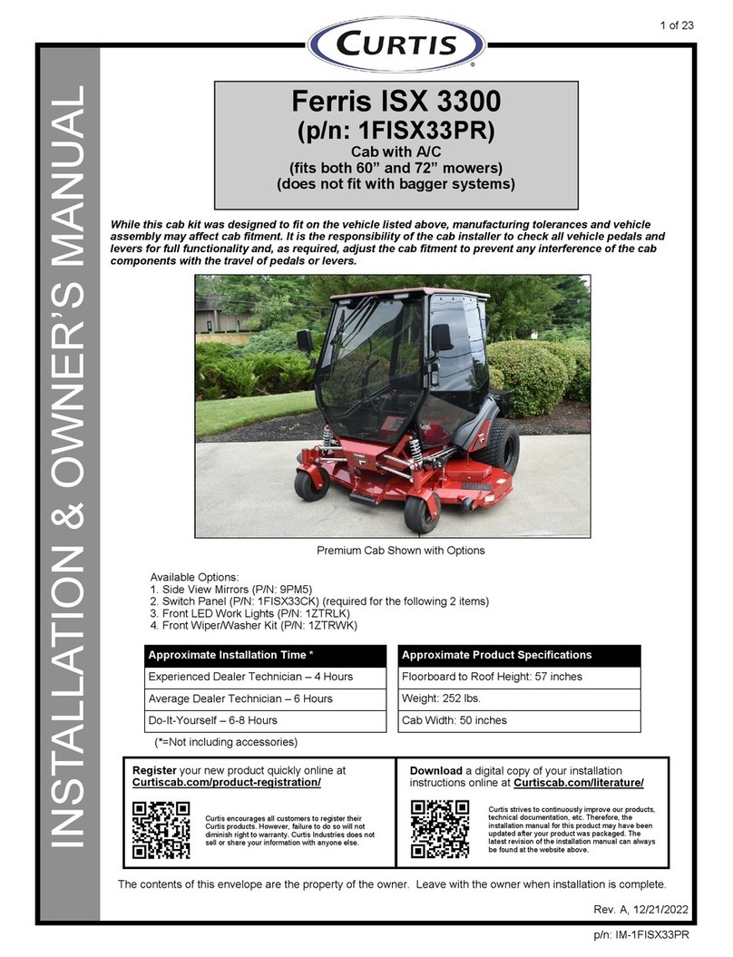
INSTALLATION & OWNER’S MANUAL
Kubota ZD1211
(p/n: 1KUBZD1211PR2)
Cab with A/C
(fits both 60” and 72” mowers)
(Does not fit with bagger system)
Rev. B, 07/06/2023
p/n: IM-1KUBZD1211PR2
While this cab kit was designed to fit on the vehicle listed above, manufacturing tolerances
and vehicle assembly may affect cab fitment. It is the responsibility of the cab installer to
check all vehicle pedals and levers for full functionality and, as required, adjust the cab
fitment to prevent any interference of the cab components with the travel of pedals or levers.
(*=Not including accessories)
Available Options:
1. Side View Mirrors (P/N: 9PM5)
2. Switch Panel (P/N: 1KUBZD1211CK) (req’d for following 2 items)
3. Front LED Work Lights (P/N: 1KUBZD1211LK)
4. Front Wiper/Washer Kit (P/N: 1KUBZD1211WK)
Approximate Installation Time *
Experienced Dealer Technician – 4 Hours
Average Dealer Technician – 6 Hours
Do-It-Yourself – 6-8 Hours
Approximate Product Specifications
Floorboard to Roof Height: 60 inches
Weight: 240 lbs.
Cab Width: 54 inches
The contents of this envelope are the property of the owner. Leave with the owner when installation is complete.
Register your new product quickly online at
Curtiscab.com/product-registration/
Download a digital copy of your installation
instructions online at Curtiscab.com/literature/
Curtis encourages all customers to register their
Curtis products. However, failure to do so will not
diminish right to warranty. Curtis Industries does not
sell or share your information with anyone else.
Curtis strives to continuously improve our products,
technical documentation, etc. Therefore, the
installation manual for this product may have been
updated after your product was packaged. The
latest revision of the installation manual can always
be found at the website above.
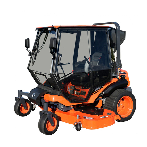
Premium Cab Shown with Options

2 of 35
TABLE OF CONTENTS
WARNINGS, TIPS, & REQUIRED TOOLS...................................................... 3
VEHICLE PREP........................................................................................... 4-8
DYNAMO INSTALLATION .............................................................................. 9
CAB INSTALLATION................................................................................ 10-25
CAB FEATURES & OPERATION.................................................................. 26
CARE AND MAINTENANCE......................................................................... 27
TROUBLESHOOTING.................................................................................. 27
BELT ADJUSTMENT .................................................................................... 28
SERVICE PARTS .................................................................................... 29-34
BOLT TORQUE SPECIFICATIONS .............................................................. 35

3 of 35
Curtis cabs feature an assembly of parts designed for your vehicle which require adjustment
and alignment of components to accommodate vehicle variations and provide proper weather
protection. For accurate installation, proper operation, and years of satisfaction, please read
and understand the installation and owner’s manual fully prior to installing the cab.
From all of us at Curtis, we thank you for choosing our product.
HELPFUL HINTS:
•Refer to parts diagram found in the service parts section of this manual to help identify parts
during the assembly process.
•To assist with the cab installation, leave all fasteners loose for later adjustment unless
otherwise specified.
•Read and understand all instructions before beginning.
•Apply a silicone sealant to seal any minor gaps that may occur due to vehicle variations.
•Use caution to avoid damaging the factory installed threaded inserts or weld nuts. Begin the
thread engagement by hand to avoid or correct potential cross threading.
•Make sure the areas where the supplied self-adhesive hook Velcro® will be applied are
clean and dry and at room temperature for best adhesion.
driver and passenger.
Curtis accessory weights are listed in product
add additional weight to the base vehicle. All
Curtis Cabs, blades and general accessories
ADDED
WEIGHT
brochures. Deduct the accessory's total weight
from the vehicle's rated capacity and never
exceed the vehicle's rated capacity including
Exposure to Carbon Monoxide
can Cause illness, serious injury or
death. Never operate vehicle if suspicious of Carbon Monox-
ide. Inspect exhaust system for leaks monthly. Leaks can
result from loose connections, corrosion, cracks or other
damage to the exhaust manifold. If leaks are found, repair or
replace exhaust system. Do not use vehicle until repair or
replacement is complete.
•Set of Standard and Metric Sockets (3/8” + 1/2” Drive)
•3/8” + 1/2” Drive Ratchets and Long Drive Extension
•Set of Standard and Metric Open-End Wrenches
•Set of Standard and Metric Allen Wrenches
•#1, #2, and #3 Phillips Head Screwdrivers
•Torque Wrench (1/2” Drive)
•Rubber Mallet or Plastic Dead Blow Hammer
•Bungee Cord or Twine
•Hoisting Strap
•Drill/Driver
•9/32” Drill Bit
•#2 and #3 Phillips Head Bit
•Utility Knife
•Pair of Scissors
•Shears
•Grease
•Black Silicone Sealant
•Steel Straight Edge
WARNINGS, TIPS, & REQUIRED TOOLS
TOOLS REQUIRED:
GENERAL INFORMATION BEFORE YOU START
California Health and Safety Proposition 65 Warning: This product may contain chemi-
cals known to the state of California to cause cancer and birth defects or other reproductive harm.

CAB INSTALLATION
4 of 35
Fig. 1.4 (Unbolt Compressor)
Step 1: (Vehicle Prep)
1.1 Park vehicle in a location accessible by an
overhead hoist.
1.2 Disconnect the negative battery terminal.
1.3 See fig. 1.3. Remove the bolt from the battery
clamp and replace with a longer one from the
supplied hardware kit and re-use the nut, but do
not re-connect the battery.
Hardware Used Qty
5/16x1-1/4 Square Head Bolt 1
1.4 See fig. 1.4. Remove and discard the 3 bolts and
nuts securing the compressor bracket to the base
of the shipping mount and cut any zip ties holding
the hoses and wire harness to the shipping mount.
Support the compressor using a bungee cord or
rope. Do not ever use the hoses to support the
compressor or damage may occur.
1.5 Remove the Compressor mounting bracket from
the compressor. Leave the compressor
tensioning bracket attached to the compressor.
Save the 3 bolts for reuse.
Fig. 1.3 (Replace Negative Battery Bolt)
Replace

CAB INSTALLATION
5 of 35
Fig. 1.6 (Remove bolts)
Remove
Step 1: (Vehicle Prep)
1.6 Remove and discard three bolts from the left side
of the engine as shown in fig. 1.6.
1.7 See fig. 1.7. Remove and reuse two OEM bolts
and install the shroud mounting bracket. Secure
the bottom of the bracket with two M6 bolts and
two M6 nuts.
Hardware Used Qty
M6x1.0x20mm Flange Bolt 2
M6x1.0 Nylock Nut 2
1.8 See fig. 1.8. Install the compressor mounting
bracket behind the alternator wiring. The
alternator wiring does not need to be removed, but
be careful going past with the bracket. Secure
with the hardware listed below.
Hardware Used Qty
M10x1.25x30mm Flange Bolt 3
Note: Ensure there is a gap between the alternator
power wire and the compressor mounting bracket.
If needed, loosen the nut, rotate the wire down,
and re-tighten the nut. Reuse
M6 Bolts
and Nuts
Fig. 1.7 (Install shroud mounting bracket)
Fig. 1.8 (Install compressor mounting bracket)
M10 Bolts
M10 Bolt
Gap
Loosen and
Rotate if needed

CAB INSTALLATION
6 of 35
Fig. 1.11 (Right Drive Lever Filler)
Fig. 1.9 (Right Side Drive Lever Cover)
Fig. 1.12 (Drive Lever Filler Orientation)
Install Shoulder
Screw
Fig. 1.10 (Drive Lever Cover Velcro)
Screws
Screw,
Washers
& Nut
Velcro
Velcro Seam
Fastener Slot
1.9 See fig. 1.9. Remove the fasteners securing the
right side drive lever cover. Remove drive lever
cover by lifting up and over the drive lever. Set
aside hardware for later use. Note: Lower screw
only needs to be loosened to prevent losing any
hardware.
1.10 See fig. 1.10. Thoroughly wipe the outside of the
drive lever cover with isopropyl alcohol. Once dry,
adhere the supplied Velcro along the edge around
the entire opening as shown.
1.11 See fig. 1.11. Locate the supplied drive lever filler
labeled V-00075-R, make a cone shape by
attaching one side to the other via the factory
sewn-on vinyl.
1.12 See fig. 1.12. Align the filler’s Velcro seam with
corner opening near the cover’s fastener slot. Slip
the cone shaped drive lever filler up through the
drive lever cover. Fold the filler over and attach it
to the drive lever cover.
1.13 Repeat steps 1.9 through 1.12 on the left side of
the vehicle.

CAB INSTALLATION
7 of 35
1.14 See fig. 1.14. Locate the cotter pin retaining the
blade height adjustment knob. Remove and set
aside the cotter pin and adjustment knob.
1.15 See fig. 1.15. Remove and set aside the three
screws securing the plastic cover to the right side
fender. Pull the molded handle from the throttle
lever and engage the blade lever.
1.16 Carefully lift the cover up and over the throttle and
blade engagement levers. Disconnect the ignition
switch from its harness then place the cover aside.
Fig. 1.14 (Blade Height Adjustment Knob)
Fig. 1.15 (Right Side Cover)
Cotter Pin
Screws
Molded Handle
Removed
Blade lever in the
Engaged Position
Knob

CAB INSTALLATION
8 of 35
1.17 See fig. 1.17. Slip the supplied clip nut onto the
tab rearward of the blade engagement lever.
Hardware Used Qty
#8 Clip Nut 1
1.18 See fig. 1.18. Place the supplied sealing brush
panel over the levers as shown. Secure using the
supplied hardware listed below. Fully tighten at
this time.
Note: The 22mm O.D. x 4.95mm thick washer
(7/8” O.D. x 3/16” thick) is used as a spacer, it’s
placed underneath the brush panel.
Hardware Used Qty
#8 x 5/8” Sheetmetal Screw 1
1/2” O.D. Washer 1
22mm O.D. (.87”) Washer 1
#10-32 x 3/4” Screw 1
#10-32 Lock Nut 1
1.19 See fig. 1.19. Reinstall the large plastic cover,
ignition switch harness, molded throttle lever
handle and blade height adjustment knob along
with its cotter pin.
Reminder: Place the blade engagement lever
into the disengage position at this time.
Leave the drive lever covers off at this point
and continue installing the cab.
Fig. 1.17 (Clip Nut Orientation)
Fig. 1.18 (Brush Panel Orientation)
Clip Nut
#8 Screw &
1/2” O.D.
Washer
22mm O.D. x 4.95mm
Washer
#10-32 Hardware
Fig. 1.19 (Right Side Cover Reinstalled)

CAB INSTALLATION
9 of 35
Fig. 2.2a (Replace Tensioner Bracket)
Fig. 2.1 (Remove OEM Dynamo)
Fig. 2.2b (Install replacement Tensioner Bracket)
Step 2: (DYNAMO INSTALLATION)
2.1 See figure 2.1. Remove the OEM dynamo from the
vehicle and discard. Save the hardware for reuse.
2.2 See figures 2.2a and 2.2b. Use a 10mm wrench to
remove the OEM dynamo tensioner bracket and
discard. Reuse the hardware and install the supplied
larger bracket. Do not fully tighten the bolts at this
time.
2.3 See fig. 2.3. Mount the new dynamo in the original
location. Ensure the bolt starts on the engine side
and the washers and nut are on the dynamo side.
Do not fully tighten the hardware at this time.
2.4 Install the belt over the new dynamo pulley.
Ensure the belt is properly running on all pulleys.
See fig. 2.4.
2.5 Install the tensioner bolt. Do not fully tighten at
this time.
2.6 Tighten the 2 tensioner bracket bolts.
2.7 Tension the belt and tighten top dynamo bolt with
a 12mm wrench.
2.8 Tighten lower mounting hardware with a 13mm
wrench and a 13mm socket.
Fig. 2.3 (Mount new Dynamo)
Remove
Reuse
Remove
Reuse
New
bracket
Bolt
Nut and
washers
Fig. 2.4 (Install belt and set the tension)

CAB INSTALLATION
10 of 35
Fig. 3.1 (Remove hand screws and ROPS Bolt)
Fig. 3.3 (Remove upper bolt)
Remove
Remove
Remove
Fig. 3.6 (Tilt the ROPS)
Fig. 3.4 (Install Left ROPS Mount)
Bolt Only ROPS
Mount
Step 3: (Install ROPS Mounts)
3.1 See fig. 3.1. Remove the left and right hand
tension screws and clips on the ROPS and
discard.
3.2 Remove the ROPS pin and bolt from the left side
and discard. See fig. 3.1. Leave the right side
installed at this time.
3.3 See fig. 3.3. Remove the upper bolt on the cross
hose protector as shown and discard.
3.4 See fig. 3.4. Install the left ROPS mount using the
following hardware. The large bolt in the pivot
hole should be tightened just enough so that the
ROPS can still tilt without damaging the paint.
The large bolt in the hole where the pin was
removed, should be installed through the bracket,
but no nut is installed at this time. Tighten the
smaller M8 bolt.
Hardware Used Qty
M16x2x80mm Hex Head Bolt 2
M16x30 Steel Flat Washer 3
M16x2 Locknut 1
M8x1.25x30mm Flange Bolt 1
3.5 Repeat steps 3.2, 3.3, and 3.4 for the right side.
3.6 See fig. 3.6. Remove the lower M16 bolts from the
previous steps and tilt the ROPS back and re-use
the bolts to pin in the tilted position. Be careful not
to damage the engine hood if it is in the open
position. The nuts on the lower bolts will be
installed in a later step.
M16 Bolts

CAB INSTALLATION
11 of 35
Fig. 4.5 (Install Sealing Brushes)
Fig. 4.1 (Remove Bolts)
Fig. 4.2 (Cut Floormat)
Fig. 4.3 (Remove Pine Tree Clips)
60” Only
Cut Tabs
brushes
Step 4: (Vehicle Prep)
4.1 Remove and discard the four floorboard bolts
shown in Figure 4.1. If the mower is a 60”,
remove two additional bolts in the location shown.
4.2 See fig. 4.2. Cut the rubber tabs on the floormat at
the bolt locations as shown so that the hole is
clearly accessible.
4.3 See fig. 4.3. Remove the pine tree clips from the
floormat at the 12 locations shown.
4.4 If installing on a 60” mower, remove and save the
tilting front cover at the front of the machine.
4.5 See fig. 4.5. Install the pedal seal panel on top of
the floormat as shown. Secure to the floorpan
using the following hardware. The floorpan may
need to be lifted slightly in the front on a 60”
mower to access the center screw.
Hardware Used Qty
#10-32x3/4” Phillips Head Screw 6
#10-32 Flange Nut 6

CAB INSTALLATION
12 of 35
Fig. 4.6a (Seal location on 60”)
Fig. 4.6b (Seal location on 72”)
Fig. 4.7 (Install Spacers)
Spacers
60” Only
4.6 Install self-adhesive seal around the edge of the
floor pan as shown and cut to length. Refer to
Figure 4.6a for 60” and 4.6b for 72”.
Note: placement on the 72” machine. Seal should
follow along the white line shown in fig. 4.6b.
4.7 See fig. 4.7. Insert spacer bushings into the
depressions where the floorboard bolts were
removed. (72” uses 4 spacers, 60” uses 6
spacers)
Hardware Used Qty
1/2” Long Spacer 4 or 6
4.8 See fig. 4.8. Flip the seat forward and disconnect
the OEM regulator.
Fig. 4.8 (Disconnect OEM Regulator)
Disconnect

CAB INSTALLATION
13 of 35
Fig. 5.4 (Position lifting strap)
Fig. 4.9 (Install Velcro®)
Fig. 5.1 (Move Seat forward, Rotate seatback)
4.9 See fig. 4.9. Install the supplied adhesive Velcro®
as shown with white lines. Be sure to wipe down
the surfaces where the Velcro® will be adhered
and that the surfaces are at room temperature.
Apply between round seat bumpers
Apply along horizontal edge of fenders
Apply 3 sections underneath front seat support
frame member as indicated by dotted line.
Velcro® must be on the underside.
Step 5: (Cabin Installation)
5.1 See fig. 5.1. Lower the seat and slide the seat all
the way forward and use the knob on the seat to
tilt the seatback forward as much as possible.
5.2 Remove the doors from the cabin and set aside
carefully to prevent scratching the panels.
5.3 Remove the 3 bolts securing the compressor
bracket to the base of the shipping mount and cut
any zip ties holding the hoses and wire harness to
the shipping mount. Support the compressor
using a bungee cord or rope. Do not ever use the
hoses to support the compressor or damage may
occur.
5.4 See fig. 5.4. Position a lifting strap where shown
so that it sits roughly 2” in front of the b-pillar.
Lifting Strap

CAB INSTALLATION
14 of 35
Fig. 5.5a (Remove Rear Bolts)
Fig. 5.5b (Remove Lag Screws)
Fig. 5.8 (Install Rear Bolts)
Remove
Inside Cab
Install
Install
Fig. 5.9 (Install Floorboard Bolts)
M8
M8 on
60”
5.5 See figures 5.5a and b. Put tension on the lifting
strap with the overhead hoist. Remove and
discard the 4 bolts holding the rear of the cab
down to the shipping bracket (located inside the
cab) as well as the 4 lag screws holding the
floorboards to the pallet.
5.6 With assistance, lift the cabin and position over the
vehicle. Be sure to support the A/C compressor
so that it never hangs from the hoses.
5.7 Lower the cabin slowly onto the vehicle being
careful to not scratch the fenders with the rear
edge of the floorboard. The A/C compressor
should pass to the inside of the ROPS and end up
on the left side of the engine.
5.8 See fig. 5.8. Fasten the rear of the cabin to the
ROPS mounts using the following hardware.
Leave loose at this time.
Hardware Used Qty
5/16-18 x 1-3/4 Hex Head Bolt 4
5/16-18 Flange Nut 4
5.9 See fig. 5.9. Fasten the cab to the floor of the
tractor using the following hardware. Note: On 60”
tractors, use 6 M8 bolts. On 72” tractors, only
install 4 M8 bolts and leave additional slot open.
Hardware Used Qty
M8x1.25x40mm Button Head Bolt 4 or 6
5/16x1-1/4” Steel Fender Washers 4 or 6
1/4-20x1” Button Head Bolt 6
1/4x1” Steel Fender Washers 6
1/4-20 Flange Nut 6
5.10 Tighten all floorboard bolts and rear cabin bolts at
this time
5.11 Raise ROPS bar and loosely re-install M16 bolts
used to pin it.

CAB INSTALLATION
15 of 35
Fig. 5.12 (Loosen Upper ROPS Mount)
Fig. 5.13 (Install Upper ROPS Clamp Plate)
Fig. 5.15 (Tighten ROPS Bolts)
Loosen
Install Clamp
Plate
Torque
Fig. 5.16 (Drill Hole on 72” Mowers)
Drill
on 72”
5.12 See fig. 5.12. Loosen the 4 factory installed 5/16”
bolts securing the upper ROPS mount so that the
mount can slide up against the underside of the
ROPS.
5.13 See fig. 5.13. Install the upper ROPS clamp plate
to the top side of the ROPS and secure with the
following hardware. Bolts can be tightened at this
time. Hand tighten only. Do not over-tighten or
plate will deform.
Hardware Used Qty
5/16-18x2-1/2” Flange Bolts 4
5/16x1” Steel Fender Washers 8
5/16-18 Flange Nut 4
5.14 Re-tighten the bolts loosened in step 5.12.
5.15 See fig. 5.15. Install the washer and nuts onto the
M16 ROPS bolts and tighten at this time. Note:
The tightening torque is different for the upper and
lower bolt.
Torque the upper bolt to 167 to 196 Nm (123 to
144 lbf-ft)
Torque the lower bolt to 78 to 90 Nm (58 to 66 lbf-
ft)
Hardware Used Qty
M16x30 Steel Flat Washer 1
M16x2 Locknut 1
5.16 See fig. 5.16. If installed on a 72” mower, drill
9/32” holes through the tractor floorboard centered
on the open slots in the cab floorboards. Do not
drill too deep to avoid damaging any items on the
underside of the floorboard.
5.17 Dab the raw edge of the holes in the steel
floorboard with some orange touch-up paint to
prevent corrosion.
5.18 Install the following hardware into the newly drilled
holes and tighten.
Hardware Used Qty
1/4-20x1” Button Head Bolt 2
1/4x1” Steel Fender Washers 2
1/4-20 Flange Nut 2

CAB INSTALLATION
16 of 35
Step 6: (Compressor Installation)
6.1 Move compressor into location on the left side of
the engine and secure to the bracket with the
hardware removed on step 1.8. See figure 6.1.
Do not tighten hardware at this time.
Hardware Used Qty
M10x1.25x30mm Flange Bolt 3
6.2 See fig. 6.2. Install the supplied belt and tension.
Tighten all compressor pivot bolts at this time.
Note: The oil pressure sensor wire might be close
to contacting the belt. To ensure proper
clearance, the terminal might have to be bent
downward.
6.3 See fig. 6.3. Install the supplied rubber grommet
to the left side ROPS bracket.
Fig. 6.2 (Install Belt and Tension)
Fig. 6.1 (Install Compressor)
Fig. 6.3 (Install Rubber Grommet)
Bolts Bolt
Belt
Grommet
Bend down for
clearance

CAB INSTALLATION
17 of 35
Fig. 7.1 (Connect Dynamo Wire Harness)
6.4 See figs. 6.4a and 6.4b. Pass the regulator wiring
through the grommet and install the regulator to
the front of the left ROPS bracket. With one of the
regulator mounting bolts and nuts, secure the A/C
hose with a p-clamp as shown in figure 6.4b.
Twist clamp and adjust hose position so that hose
does not contact sharp edges of ROPS bracket.
Hardware Used Qty
1/4-20x1-1/2” Socket Head Bolt 2
1/4-20 Flange Nut 2
3/4” P-Clamp 2
Step 7: (Wiring)
7.1 See fig. 7.1. Connect the dynamo and regulator
power wiring harnesses to the regulator. Use
another p-clamp to secure the A/C hose further
down the ROPS clamp than in step 6.4, and
sandwich the ground wire from the regulator and
ground wire from the regulator power harness
between the p-clamp and ROPS bracket. Twist
clamp and adjust hose position so that hose does
not contact sharp edges of ROPS bracket.
Hardware Used Qty
1/4-20x1” Button Head Bolt 1
1/4-20 Flange Nut 1
3/4” P-Clamp 1
Fig. 6.4a (Secure Regulator to ROPS Bracket)
Fig. 6.4b (Secure Regulator to ROPS Bracket)
Regulator
Wires through
grommet
P-Clamp
Ground Wires
and P-Clamp

CAB INSTALLATION
18 of 35
Fig. 7.2 (Connect Dynamo Wiring Harness)
Fig. 7.3 (Cable Tie Hoses)
Fig. 7.5 (P-Clamp Wire Harness to ROPS Bracket)
Cable
Tie
P-Clamps
Fig. 7.6 (Secure Wire Harness)
Cable
Ties
7.2 See fig. 7.2. Connect the dynamo wiring harness
to the dynamo.
7.3 See fig. 7.3. Secure both hoses to the vehicle
frame using a cable tie as shown. Ensure that the
hoses will not contact any sharp edges.
Hardware Used Qty
Cable Tie 1
7.4. Route the regulator power harness forward over
the ROPS tube but below the flat area that the
hood seals on when it is closed.
Avoid any moving parts.
Continue running the harness under the seat and
around to the other side. Route it over the right
side of the ROPS, again below the flat area that
the hood seals on when it is closed.
7.5 See fig. 7.5. Cut the cable ties securing the wiring
harness and attach the harness to the lower
ROPS brackets with p-clamps as shown.
Hardware Used Qty
1/4-20x1” Button Head Bolt 2
1/4-20 Flange Nut 2
3/4” P-Clamp 2
7.6 See fig. 7.6. Using two cable ties, secure the wire
harness to the compressor lines just below the
regulator connectors and another where
compressor lines bend to go to the compressor.
Ensure that the wire harness will not contact any
sharp edges. Make sure hood closes without
hitting the wire harness.
Hardware Used Qty
Cable Ties 2

CAB INSTALLATION
19 of 35
Fig. 7.10 (Install Switch Bracket)
Bolt
Fig. 7.7 (Attach Red Wires to Battery)
Fig. 7.8 (Route Harness to Right Control Stick)
Fig. 7.9 (Connect Wires to Switch)
Take Image During Pilot Install
M6 Nut
7.7 See fig. 7.7. Install the ring terminals on the red
wires from both the main harness and from the
regulator power harness onto the stud on the
positive battery clamp (outboard of the existing
battery clamp nut) and secure with the following
hardware.
Hardware Used Qty
M6x1.0 Nut 1
7.8 See fig. 7.8. Locate the portion of the wire harness
with two ring terminals crimped on the ends of
black and gray wires. Route the ring terminals
forward over the ROPS tube in front of the battery
next to the existing wiring and up along the right
side of the vehicle to right hand control.
Note: Wires must be routed above the ROPS, but
below the flat area that the hood seals on when it
is closed.
Avoid any moving parts.
7.9 See fig. 7.9. Route the wires up behind the right
control stick and connect to the supplied switch as
shown. The gray wire should go to the center
screw (NO, #3) and the black wire should be
connected to the COM, #1 screw.
It is recommended to do the assembly over the
floor of the tractor to prevent losing any screws.
7.10 Remove the bolt shown in figure 7.10 and re-
install with the switch bracket so that the spring
loaded switch rod will be contacted by the throttle
control lever. Adjust the bracket and switch so
that when the throttle control lever is beyond 3/4
throttle the switch is engaged. The switch can be
rotated on the bracket and the bracket can also be
rotated where it mounts to the vehicle.

CAB INSTALLATION
20 of 35
7.11 See fig. 7.11. Install the right side drive lever cover
and the previously attached vinyl filler using the
hardware removed during step 1.9.
7.12 See fig. 7.12. Once the drive lever cover hardware
has been tightened, move the lever all the way out
away from the operator, in the park position. Using
a China marker or other non-permanent marker,
make a mark on the drive handle at the top of the
filler. Wipe area with isopropyl alcohol and adhere
a piece of the supplied Velcro around handle at
the mark previously made.
7.13 See fig. 7.13. Wrap filler around drive lever
attaching Velcro on filler to Velcro on handle.
7.14 Repeat steps 7.11 through 7.13 on the left side.
Fig. 7.12 (Drive Lever Velcro)
Fig. 7.13 (Filler to Handle)
Fig. 7.11 (Drive Lever Cover & Filler)
Other manuals for Kubota ZD1211
1
This manual suits for next models
1
Table of contents
Other Curtis Lawn Mower manuals